warning light TOYOTA COROLLA HYBRID 2023 Owners Manual
[x] Cancel search | Manufacturer: TOYOTA, Model Year: 2023, Model line: COROLLA HYBRID, Model: TOYOTA COROLLA HYBRID 2023Pages: 496, PDF Size: 10.13 MB
Page 380 of 496
3807-2. Steps to take in an emergency
steering system warning light may
come on and the warning buzzer
may sound.
■When the tire pressure warning
light comes on
Inspect the tires to check if a tire is
punctured.
If a tire is punctured: P.387, 398
If none of the tires are punctured:
Turn the power switch off then turn it
to ON. Check if the tire pressure
warning light comes on or blinks.
If the tire pressure warning light
blinks for approximately 1 minute
then stays on
There may be a malfunction in the
tire pressure warning system. Have
the vehicle inspected by your Toyota
dealer immediately.
If the tire pressure warning light
comes on
1 After the temperature of the tires
has lowered sufficiently, check
the inflation pressure of each tire
and adjust them to the specified
level.
2 If the warning light does not turn
off even after several minutes
have elapsed, check that the
inflation pressure of each tire is
at the specified level and perform
initialization. ( P.333)
■The tire pressure warning light
may come on due to natural
causes
The tire pressure warning light may
come on due to natural causes such
as natural air leaks and tire inflation
pressure changes caused by tem-
perature. In this case, adjusting the
tire inflation pressure will turn off the
warning light (after a few minutes).
■When a tire is replaced with a
spare tire
Vehicles with a compact spare tire:
The compact spare tire is not
equipped with a tire pressure warn-
ing valve and transmitter. If a tire
goes flat, the tire pressure warning light will not turn off even though the
flat tire has been replaced with the
spare tire. Replace the spare tire
with the repaired tire and adjust the
tire inflation pressure. The tire pres-
sure warning light will go off after a
few minutes.
■Conditions that the tire pres-
sure warning system may not
function properly
P.329
WARNING
■If both the ABS and the brake
system warning lights remain
on
Stop your vehicle in a safe place
immediately and contact your Toy-
ota dealer.
The vehicle will become
extremely unstable during brak-
ing, and the ABS system may fail,
which could cause an accident
resulting in death o r serious injury.
■When the electric power
steering system warning light
comes on
When the light comes on yellow,
the assist to the power steering is
restricted. When the light comes
on red, the assis t to the power
steering is lost and handling oper-
ations of the steering wheel
become extremely heavy.
When steering wheel operations
are heavier than usual, grip the
steering wheel firmly and operate
it using more fo rce than usual.
■If the tire pressure warning
light comes on
Be sure to observe the following
precautions.
Failure to do so could cause a
loss of vehicle control and result
in death or serious injury.
Page 381 of 496
3817-2. Steps to take in an emergency
7
When trouble arises
WARNING
●Stop your vehicle in a safe place
as soon as possible. Adjust the
tire inflation pressure immedi-
ately.
●Vehicles with a compact spare
tire: If the tire pressure warning
light comes on ev en after tire
inflation pressure adjustment, it
is probable that you have a flat
tire. Check the tires. If a tire is
flat, change it with the spare tire
and have the flat tire repaired by
the nearest Toy ota dealer.
●Vehicles with emergency tire
puncture repair kit: If the tire
pressure warning light comes
on even after tire inflation pres-
sure adjustment, it is probable
that you have a flat tire. Check
the tires. If a tire is flat, repair
the flat tire by using emergency
tire puncture repair kit.
●Avoid abrupt maneuvering and
braking.
If the vehicle tires deteriorate,
you could lose control of the
steering wheel or the brakes.
■If a blowout or sudden air
leakage should occur
The tire pressure warning system
may not activate immediately.
■Maintenance of the tires
Each tire, including the spare (if
provided), should be checked
monthly when cold and inflated to
the inflation pressure recom-
mended by the vehicle manufac-
turer on the vehicle placard or tire
inflation pressure label (tire and
load information label). (If your
vehicle has tires of a different size
than the size indicated on the
vehicle placard or tire inflation
pressure label [tire and load infor-
mation label], you should deter-
mine the proper tire inflation
pressure for those tires.)
As an added safety feature, your
vehicle has been equipped with a
tire pressure monitoring system
(TPMS-tire pressure warning sys-
tem) that illuminates a low tire
pressure telltale (tire pressure
warning light) w hen one or more
of your tires is significantly
under-inflated. Accordingly, when
the low tire pressure telltale (tire
pressure warning light) illumi-
nates, you should stop and check
your tires as soon as possible,
and inflate them to the proper
pressure. Driving on a signifi-
cantly under-inflated tire causes
the tire to overhea t and can lead
to tire failure. Under-inflation also
reduces fuel efficiency and tire
tread life, and may affect the vehi-
cle’s handling and stopping ability.
Please note that the TPMS (tire
pressure warning system) is not a
substitute for proper tire mainte-
nance, and it is the driver’s
responsibility to m aintain correct
tire pressure, even if under-infla-
tion has not reached the level to
trigger illumination of the TPMS
low tire pressure te lltale (tire pres-
sure warning light).
Your vehicle has also been
equipped with a TPMS (tire pres-
sure warning system) malfunc-
tion indicator to indicate when the
system is not operating properly.
The TPMS (tire pressure warning
system) malfunction indicator is
combined with the low tire pres-
sure telltale (tire pressure warning
light). When the system detects a
malfunction, the te lltale will flash
for approximately one minute and
then remain continuously illumi-
nated. This sequence will con-
tinue upon subsequent vehicle
start-ups as long as the malfunc-
tion exists. When the malfunction
indicator is illuminated, the sys-
tem may not be ab le to detect or
signal low tire pressure as
intended.
Page 382 of 496
3827-2. Steps to take in an emergency
■Warning messages
The warning messages explained
below may differ from the actual
messages according to operation
conditions and vehicle specifica-
tions.
■Warning buzzer
A buzzer may sound when a mes-
sage is displayed.
The buzzer may not be audible if the
vehicle is in a noisy location or if the
audio system volume is high.
■If “Engine Oil Level Low Add or
Replace” is displayed
The engine oil level is low. Check
WARNING
TPMS (tire pressure warning sys-
tem) malfunctions may occur for a
variety of reasons, including the
installation of replacement or
alternate tires or wheels on the
vehicle that prevent the TPMS
(tire pressure warning system)
from functioning properly. Always
check the TPMS (tire pressure
warning system) malfunction tell-
tale after replacing one or more
tires or wheels on your vehicle to
ensure that the r eplacement or
alternate tires and wheels allow
the TPMS (tire pressure warning
system) to continue to function
properly.
NOTICE
■To ensure the tire pressure
warning system operates
properly
Do not install tires with different
specifications or makers, as the
tire pressure warning system may
not operate properly.
If a war ning message
is displayed
The multi-information dis-
play shows warnings for
system malfunctions and
incorrectly performed oper-
ations, and messages that
indicate a need for mainte-
nance. When a message is
displayed, perform the
appropriate corrective
action for the message.
If a warning message is dis-
played again after the
appropriate actions have
been performed, contact
your Toyota dealer.
Additionally, if a warning
light comes on or flashes at
the same time that a warn-
ing message is displayed,
take the appropriate correc-
tive action for the warning
light. ( P.372)
Page 396 of 496
3967-2. Steps to take in an emergency
3Disconnect the hose from the
valve, remove the air release cap
from the hose and then recon-
nect the hose.
4 Turn the compressor switch on
and wait for several seconds,
and then turn it off. Check that
the air pressure indicator shows
the specified air pressure.
( P.426)
If the air pressure is under the des-
ignated pressure, turn the compres-
sor switch on again and repeat the
inflation procedure until the speci-
fied air pressure is reached.
■After a tire is repaired with the
emergency tire puncture repair
kit
●The tire pressure warning valve
and transmitter should be
replaced.
●Even if the tire inflation pressure is
at the recommended level, the tire
pressure warning light may come
on/flash.
WARNING
■Do not drive the vehicle with
a flat tire
Do not continue driving with a flat
tire.
Driving even a short distance with
a flat tire can damage the tire and
the wheel beyond repair.
Driving with a flat tire may cause a
circumferential groove on the side
wall. In such a case, the tire may
explode when using a repair kit.
■When fixing the flat tire
●Stop your vehicle in a safe and
flat area.
●Do not touch the wheels or the
area around the brakes immedi-
ately after the vehicle has been
driven.
After the vehicle has been
driven, the whee ls and the area
around the brakes may be
extremely hot. Touching these
areas with hands, feet or other
body parts may result in burns.
●Connect the valve and hose
securely with the tire installed
on the vehicle. If the hose is not
properly connected to the valve,
air leakage may occur as seal-
ant may be sprayed out.
●If the hose comes off the valve
while inflating the tire, there is a
risk that the hose will move
abruptly due to air pressure.
●After inflation of the tire has
completed, the sealant may
splatter when the hose is dis-
connected or some air is let out
of the tire.
●Follow the operation procedure
to repair the tire. If the proce-
dures not followed, the sealant
may spray out.
●Keep back from the tire while it
is being repaired, as there is a
chance of it bursting while the
repair operation is being per-
formed. If you notice any cracks
or deformation of the tire, turn
off the compressor switch and
stop the repair operation imme-
diately.
●The repair kit may overheat if
operated for a long period of
time. Do not operate the repair
kit continuously for more than
40 minutes.
Page 401 of 496
4017-2. Steps to take in an emergency
7
When trouble arises
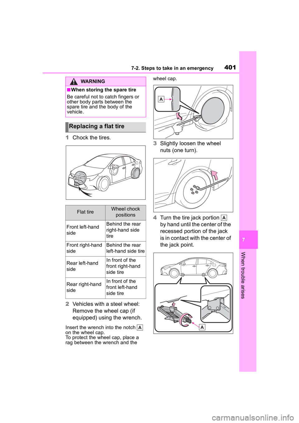
1Chock the tires.
2 Vehicles with a steel wheel:
Remove the wheel cap (if
equipped) using the wrench.
Insert the wrench into the notch
on the wheel cap.
To protect the wheel cap, place a
rag between the wrench and the wheel cap.
3
Slightly loosen the wheel
nuts (one turn).
4 Turn the tire jack portion
by hand until the center of the
recessed portion of the jack
is in contact with the center of
the jack point.
WARNING
■When storing the spare tire
Be careful not to catch fingers or
other body parts between the
spare tire and the body of the
vehicle.
Replacing a flat tire
Flat tireWheel chock positions
Front left-hand
sideBehind the rear
right-hand side
tire
Front right-hand
sideBehind the rear
left-hand side tire
Rear left-hand
sideIn front of the
front right-hand
side tire
Rear right-hand
sideIn front of the
front left-hand
side tire
Page 402 of 496
4027-2. Steps to take in an emergency
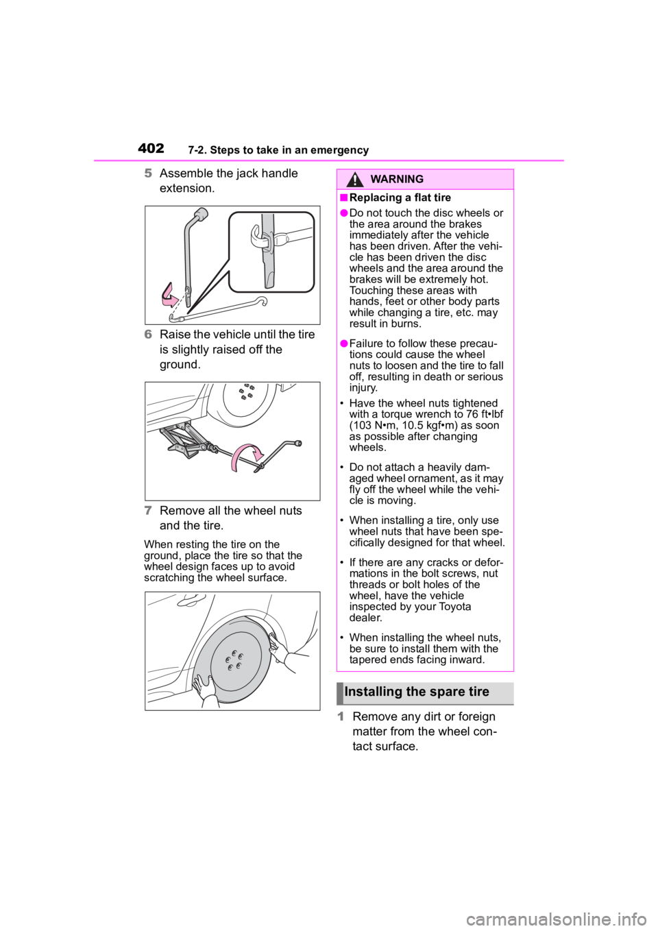
5Assemble the jack handle
extension.
6 Raise the vehicle until the tire
is slightly raised off the
ground.
7 Remove all the wheel nuts
and the tire.
When resting the tire on the
ground, place the tire so that the
wheel design faces up to avoid
scratching the wheel surface.
1 Remove any dirt or foreign
matter from the wheel con-
tact surface.
WARNING
■Replacing a flat tire
●Do not touch the disc wheels or
the area around the brakes
immediately after the vehicle
has been driven. After the vehi-
cle has been driven the disc
wheels and the area around the
brakes will be extremely hot.
Touching these areas with
hands, feet or oth er body parts
while changing a tire, etc. may
result in burns.
●Failure to follow these precau-
tions could cause the wheel
nuts to loosen and the tire to fall
off, resulting in death or serious
injury.
• Have the wheel nuts tightened
with a torque wrench to 76 ft•lbf
(103 N•m, 10.5 kgf•m) as soon
as possible after changing
wheels.
• Do not attach a heavily dam- aged wheel ornament, as it may
fly off the wheel while the vehi-
cle is moving.
• When installing a tire, only use wheel nuts that have been spe-
cifically designed for that wheel.
• If there are any cracks or defor- mations in the bolt screws, nut
threads or bolt holes of the
wheel, have the vehicle
inspected by your Toyota
dealer.
• When installing the wheel nuts, be sure to install them with the
tapered ends facing inward.
Installing the spare tire
Page 404 of 496
4047-2. Steps to take in an emergency
USE ONLY” on the tire sidewall.
Use the compact spare tire tempo-
rarily, and only in an emergency.
●Make sure to check the tire infla-
tion pressure of the compact
spare tire. (P.426)
■When the compact spare tire is
equipped
The vehicle becomes lower when
driving with the compact spare tire
compared to when driving with stan-
dard tires.
■After completing the tire
change
The tire pressure warning system
must be reset. ( P.333)
■When using the compact spare
tire
As the compact sp are tire is not
equipped with a tire pressure warn-
ing valve and transmitter, low infla-
tion pressure of the spar e tire will
not be indicated by the tire pressure
warning system. Also, if you replace
the compact spare tire after the tire
pressure warning light comes on,
the light remains on.
■If you have a flat front tire on a
road covered with snow or ice
Install the compact spare tire on one
of the rear wheels of the vehicle.
Perform the following steps and fit
tire chains to the front tires:
1 Replace a rear tire with the com-
pact spare tire.
2 Replace the flat front tire with the
tire removed from the rear of the
vehicle.
3 Fit tire chains to the front tires.
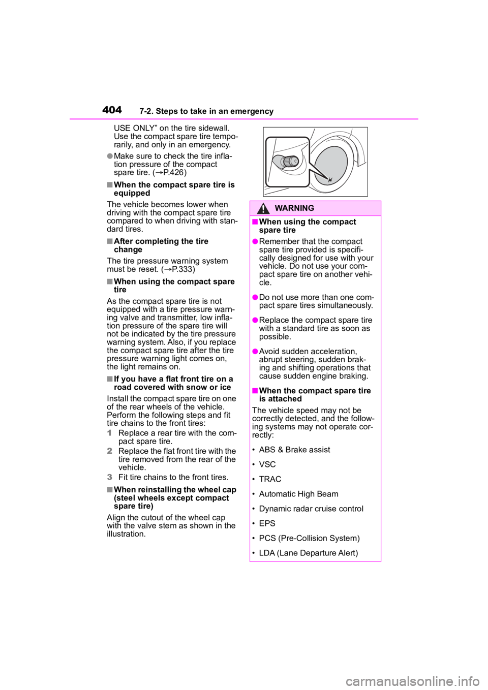
■When reinstallin g the wheel cap
(steel wheels except compact
spare tire)
Align the cutout of the wheel cap
with the valve stem as shown in the
illustration.
WARNING
■When using the compact
spare tire
●Remember that the compact
spare tire provided is specifi-
cally designed for use with your
vehicle. Do not use your com-
pact spare tire on another vehi-
cle.
●Do not use more than one com-
pact spare tires simultaneously.
●Replace the comp act spare tire
with a standard tire as soon as
possible.
●Avoid sudden acceleration,
abrupt steering, sudden brak-
ing and shifting operations that
cause sudden engine braking.
■When the compact spare tire
is attached
The vehicle speed may not be
correctly detected, and the follow-
ing systems may not operate cor-
rectly:
• ABS & Brake assist
• VSC
• TRAC
• Automatic High Beam
• Dynamic radar cruise control
• EPS
• PCS (Pre-Collision System)
• LDA (Lane Departure Alert)
Page 412 of 496
4127-2. Steps to take in an emergency
■To prevent 12-volt battery dis-
charge
●Turn off the headlights and the
audio system while the hybrid sys-
tem is off.
●Turn off any unnecessary electri-
cal components when the vehicle
is running at a low speed for an
extended period, such as in heavy
traffic.
■When the 12-volt battery is
removed or discharged
●Information stored in the ECU is
cleared. When the 12-volt battery
is depleted, have the vehicle
inspected at you r Toyota dealer.
●Some systems may require initial-
ization. (P.452)
■When removing the 12-volt bat-
tery terminals
When the 12-volt battery terminals
are removed, the information stored
in the ECU is cleared. Before
removing the 12-volt battery termi-
nals, contact your Toyota dealer.
■Charging the 1 2-volt battery
The electricity stor ed in the 12-volt
battery will discharge gradually even
when the vehicle is not in use, due
to natural discharge and the drain-
ing effects of certain electrical appli-
ances. If the vehicle is left for a long
time, the 12-volt battery may dis-
charge, and the hybrid system may
be unable to start. (The 12-volt bat-
tery recharges aut omatically while
the hybrid system is operating.)
■When recharging or replacing
the 12-volt battery (vehicles
with a smart key system)
●In some cases, it may not be pos-
sible to unlock the doors using the
smart key system when the
12-volt battery is discharged. Use
the wireless remote control or the
mechanical key to lock or unlock
the doors.
●The hybrid system may not start
on the first att empt after the 12-volt battery has recharged but
will start normally after the second
attempt. This is not a malfunction.
●The power switch mode is memo-
rized by the vehicle. When the
12-volt battery is reconnected, the
system will return to the mode it
was in before the 12-volt battery
was discharged. Before discon-
necting the 12-volt battery, turn
the power switch off.
If you are unsure what mode the
power switch was in before the
12-volt battery discharged, be
especially careful when recon-
necting the 12-volt battery.
■When replacing t
he 12-volt bat-
tery
●Use a 12-volt battery that con-
forms to European regulations.
●Use a 12-volt battery that the case
size is same as the previous one
(LN1), 20 hour rate capacity
(20HR) is equivalent (45Ah) or
greater, and per formance rating
(CCA) is equivalent (295A) or
greater.
• If the sizes differ, the 12-volt bat-
tery cannot be properly secured.
• If the 20 hour rate capacity is low,
even if the time p eriod where the
vehicle is not used is a short time,
the 12-volt battery may discharge
and the hybrid system may not be
able to start.
●For details, cons ult your Toyota
dealer.
WARNING
■When removing the 12-volt
battery terminals
Always remove the negative (-)
terminal first. If the positive (+) ter-
minal contacts any metal in the
surrounding area when the posi-
tive (+) terminal is removed, a
spark may occur, leading to a fire
in addition to ele ctrical shocks
and death or serious injury.
Page 413 of 496
4137-2. Steps to take in an emergency
7
When trouble arises
WARNING
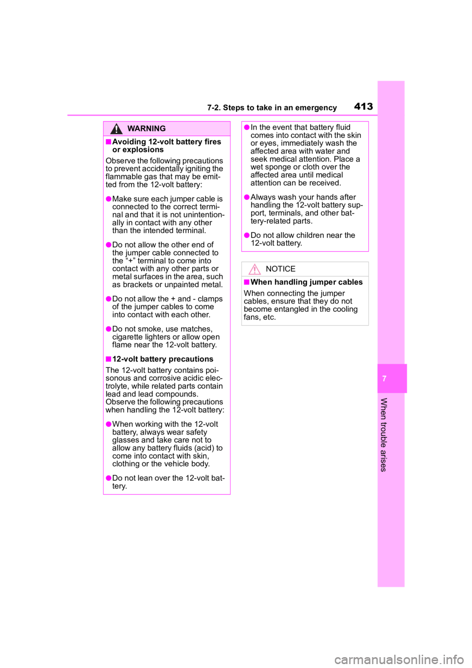
■Avoiding 12-volt battery fires
or explosions
Observe the following precautions
to prevent accidentally igniting the
flammable gas that may be emit-
ted from the 12-volt battery:
●Make sure each jumper cable is
connected to the correct termi-
nal and that it is not unintention-
ally in contact with any other
than the intended terminal.
●Do not allow the other end of
the jumper cable connected to
the “+” terminal to come into
contact with any other parts or
metal surfaces in the area, such
as brackets or unpainted metal.
●Do not allow the + and - clamps
of the jumper cables to come
into contact with each other.
●Do not smoke, use matches,
cigarette lighters or allow open
flame near the 12-volt battery.
■12-volt battery precautions
The 12-volt battery contains poi-
sonous and corrosi ve acidic elec-
trolyte, while related parts contain
lead and lead compounds.
Observe the following precautions
when handling the 12-volt battery:
●When working with the 12-volt
battery, always wear safety
glasses and take care not to
allow any battery fluids (acid) to
come into contact with skin,
clothing or the vehicle body.
●Do not lean over the 12-volt bat-
tery.
●In the event that battery fluid
comes into contact with the skin
or eyes, immediately wash the
affected area with water and
seek medical attention. Place a
wet sponge or cloth over the
affected area until medical
attention can be received.
●Always wash your hands after
handling the 12-volt battery sup-
port, terminals, and other bat-
tery-related parts.
●Do not allow children near the
12-volt battery.
NOTICE
■When handling jumper cables
When connecting the jumper
cables, ensure that they do not
become entangled in the cooling
fans, etc.
Page 425 of 496
4258-1. Specifications
8
Vehicle specifications
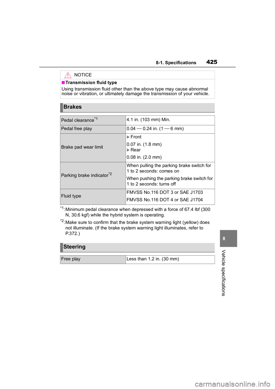
*1: Minimum pedal clearance when depressed with a force of 67.4 lbf (300
N, 30.6 kgf) while the hyb rid system is operating.
*2: Make sure to confirm that the brake system warning light (yellow) does
not illuminate. (If the brake system warning light illuminates, refer to
P.372.)
NOTICE
■Transmission fluid type
Using transmission fluid other than the above type may cause ab normal
noise or vibration, or ultimately damage the transmission of yo ur vehicle.
Brakes
Pedal clearance*14.1 in. (103 mm) Min.
Pedal free play0.04 0.24 in. (1 6 mm)
Brake pad wear limit
Front
0.07 in. (1.8 mm)
Rear
0.08 in. (2.0 mm)
Parking brake indicator*2
When pulling th e parking brake switch for
1 to 2 seconds: comes on
When pushing the parking brake switch for
1 to 2 seconds: turns off
Fluid typeFMVSS No.116 DOT 3 or SAE J1703
FMVSS No.116 DOT 4 or SAE J1704
Steering
Free playLess than 1.2 in. (30 mm)