ECO mode TOYOTA HIGHLANDER 2012 XU40 / 2.G Service Manual
[x] Cancel search | Manufacturer: TOYOTA, Model Year: 2012, Model line: HIGHLANDER, Model: TOYOTA HIGHLANDER 2012 XU40 / 2.GPages: 636, PDF Size: 11.24 MB
Page 555 of 636
5
When trouble arises
555
5-2. Steps to take in an emergency
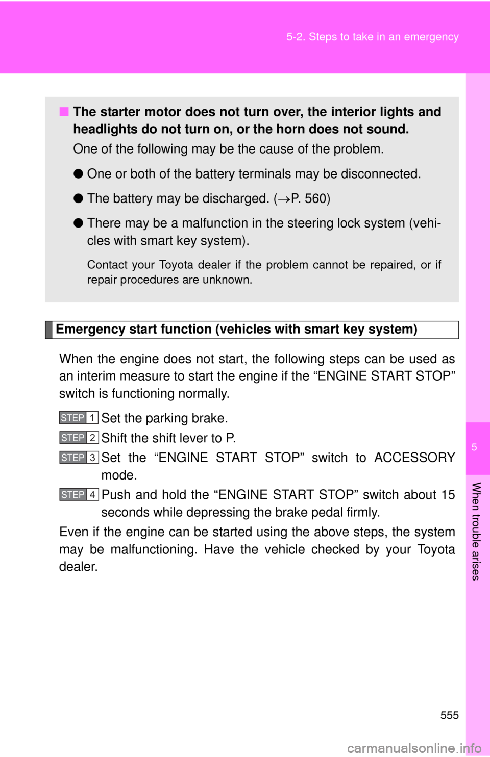
Emergency start function (vehicles with smart key system)
When the engine does not start, the following steps can be used as
an interim measure to start the engine if the “ENGINE START STOP”
switch is functioning normally. Set the parking brake.
Shift the shift lever to P.
Set the “ENGINE START ST OP” switch to ACCESSORY
mode.
Push and hold the “ENGINE START STOP” switch about 15
seconds while depressing the brake pedal firmly.
Even if the engine can be start ed using the above steps, the system
may be malfunctioning. Have the vehicle checked by your Toyota
dealer.
■ The starter motor does not turn over, the interior lights and
headlights do not turn on, or the horn does not sound.
One of the following may be the cause of the problem.
● One or both of the battery terminals may be disconnected.
● The battery may be discharged. ( P. 560)
● There may be a malfunction in the steering lock system (vehi-
cles with smart key system).
Contact your Toyota dealer if the problem cannot be repaired, or if
repair procedures are unknown.
STEP1
STEP2
STEP3
STEP4
Page 559 of 636
5
When trouble arises
559
5-2. Steps to take in an emergency
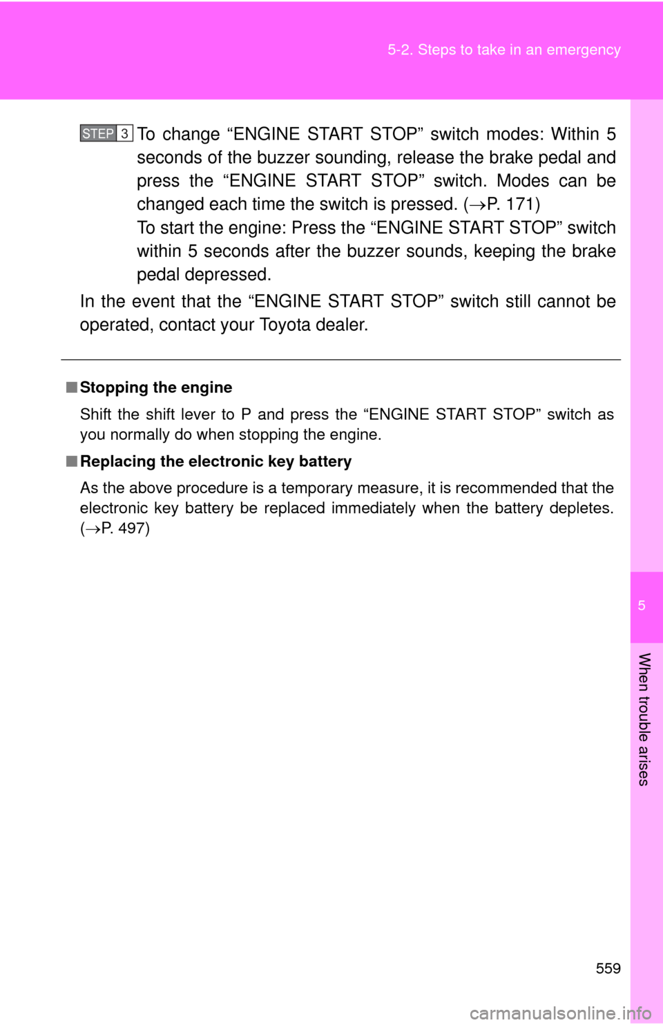
To change “ENGINE START STOP” switch modes: Within 5
seconds of the buzzer soundin
g, release the brake pedal and
press the “ENGINE START STOP” switch. Modes can be
changed each time the sw itch is pressed. (P. 171)
To start the engine: Press the “ENGINE START STOP” switch
within 5 seconds after the buzz er sounds, keeping the brake
pedal depressed.
In the event that the “ENGINE ST ART STOP” switch still cannot be
operated, contact your Toyota dealer.
■ Stopping the engine
Shift the shift lever to P and press the “ENGINE START STOP” switch as
you normally do when stopping the engine.
■ Replacing the electronic key battery
As the above procedure is a temporary measure, it is recommended that the
electronic key battery be replaced immediately when the battery depletes.
(P. 497)
STEP3
Page 562 of 636
562 5-2. Steps to take in an emergency
■Starting the engine when the battery is discharged
The engine cannot be started by push-starting.
■ To prevent battery discharge
●Turn off the headlights and the audio system while the engine is turned
off.
● Turn off any unnecessary electrical components when the vehicle is run-
ning at a low speed for an extended period, such as in heavy traffic, etc.
■ When the battery is removed or discharged
●The power back door must be initialized ( P. 6 4 )
● The tire inflation pressure warning system must be initialized. ( P. 480)
■ Charging the battery
The electricity stored in the battery will discharge gradually even when the
vehicle is not in use, due to natural discharge and the draining effects of cer-
tain electrical appliances. If the vehicle is left for a long time, the battery may
discharge, and the engine may be unable to start. (The battery recharges
automatically during driving.)
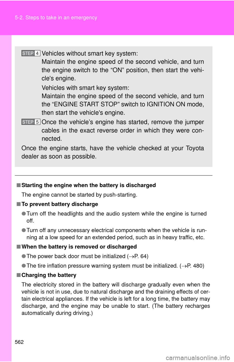
Vehicles without smart key system:
Maintain the engine speed of the second vehicle, and turn
the engine switch to the “ON” position, then start the vehi-
cle's engine.
Vehicles with smart key system:
Maintain the engine speed of the second vehicle, and turn
the “ENGINE START STOP” switch to IGNITION ON mode,
then start the vehicle's engine.
Once the vehicle’s engine has started, remove the jumper
cables in the exact reverse order in which they were con-
nected.
Once the engine starts, have the vehicle checked at your Toyota
dealer as soon as possible.STEP4
STEP5
Page 582 of 636
582 6-1. Specifications
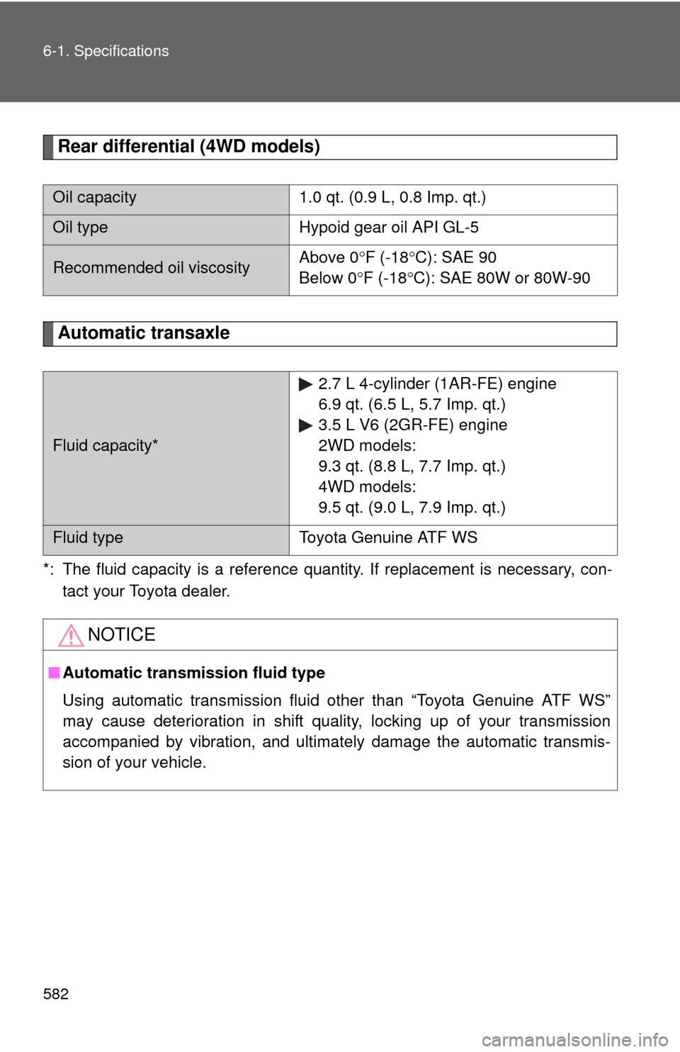
Rear differential (4WD models)
Automatic transaxle
*: The fluid capacity is a reference quantity. If replacement is necessary, con-tact your Toyota dealer.
Oil capacity 1.0 qt. (0.9 L, 0.8 Imp. qt.)
Oil typeHypoid gear oil API GL-5
Recommended oil viscosityAbove 0
F (-18 C): SAE 90
Below 0 F (-18 C): SAE 80W or 80W-90
Fluid capacity* 2.7 L 4-cylinder (1AR-FE) engine
6.9 qt. (6.5 L, 5.7 Imp. qt.)
3.5 L V6 (2GR-FE) engine
2WD models:
9.3 qt. (8.8 L, 7.7 Imp. qt.)
4WD models:
9.5 qt. (9.0 L, 7.9 Imp. qt.)
Fluid type
Toyota Genuine ATF WS
NOTICE
■Automatic transmission fluid type
Using automatic transmission fluid other than “Toyota Genuine ATF WS”
may cause deterioration in shift quality, locking up of your transmission
accompanied by vibration, and ultimately damage the automatic transmis-
sion of your vehicle.
Page 583 of 636
583
6-1. Specifications
6
Vehicle specifications
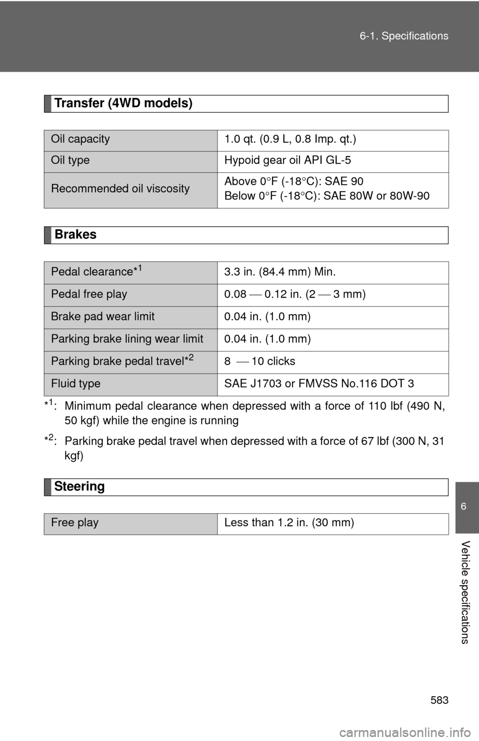
Transfer (4WD models)
Brakes
*1: Minimum pedal clearance when depressed with a force of 110 lbf (490 N,
50 kgf) while the engine is running
*
2: Parking brake pedal travel when depress ed with a force of 67 lbf (300 N, 31
kgf)
Steering
Oil capacity 1.0 qt. (0.9 L, 0.8 Imp. qt.)
Oil typeHypoid gear oil API GL-5
Recommended oil viscosityAbove 0
F (-18 C): SAE 90
Below 0 F (-18 C): SAE 80W or 80W-90
Pedal clearance*13.3 in. (84.4 mm) Min.
Pedal free play 0.08 0.12 in. (2 3 mm)
Brake pad wear limit 0.04 in. (1.0 mm)
Parking brake lining wear limit 0.04 in. (1.0 mm)
Parking brake pedal travel*28 10 clicks
Fluid type SAE J1703 or FMVSS No.116 DOT 3
Free playLess than 1.2 in. (30 mm)
Page 599 of 636
599
6-1. Specifications
6
Vehicle specifications
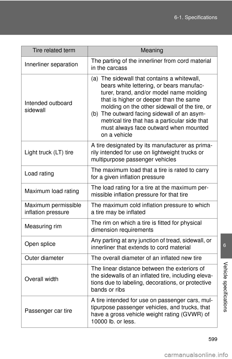
Tire related termMeaning
Innerliner separation The parting of the innerliner from cord material
in the carcass
Intended outboard
sidewall (a) The sidewall that contains a whitewall,
bears white lettering, or bears manufac-
turer, brand, and/or model name molding
that is higher or deeper than the same
molding on the other sidewall of the tire, or
(b) The outward facing sidewall of an asym- metrical tire that has a particular side that
must always face outward when mounted
on a vehicle
Light truck (LT) tire A tire designated by its manufacturer as prima-
rily intended for use on lightweight trucks or
multipurpose passenger vehicles
Load rating The maximum load that a tire is rated to carry
for a given inflation pressure
Maximum load rating The load rating for a tire at the maximum per-
missible inflation pressure for that tire
Maximum permissible
inflation pressure The maximum cold inflation pressure to which
a tire may be inflated
Measuring rim The rim on which a tire is fitted for physical
dimension requirements
Open splice Any parting at any junction of tread, sidewall, or
innerliner that extends to cord material
Outer diameter The overall diameter of an inflated new tire
Overall width The linear distance between the exteriors of
the sidewalls of an inflated tire, including eleva-
tions due to labeling, decorations, or protective
bands or ribs
Passenger car tire A tire intended for use on passenger cars, mul-
tipurpose passenger vehicles, and trucks, that
have a gross vehicle weight rating (GVWR) of
10000 lb. or less.