TOYOTA PRIUS 2001 Service Repair Manual
PRIUS 2001
TOYOTA
TOYOTA
https://www.carmanualsonline.info/img/14/57461/w960_57461-0.png
TOYOTA PRIUS 2001 Service Repair Manual
Trending: engine oil capacity, oil type, spark plugs replace, differential, center console, fuel consumption, odometer
Page 961 of 1943
F00042
1 34
6 Open
(+)(±)1 2 3
4
4 5 6
1 2
3
2 5 6
5 Continuity
ContinuityContinuity
Open
± DIAGNOSTICSANTI±LOCK BRAKE SYSTEM WITH EBD & RBS
DI±383
2001 PRIUS (RM778U)
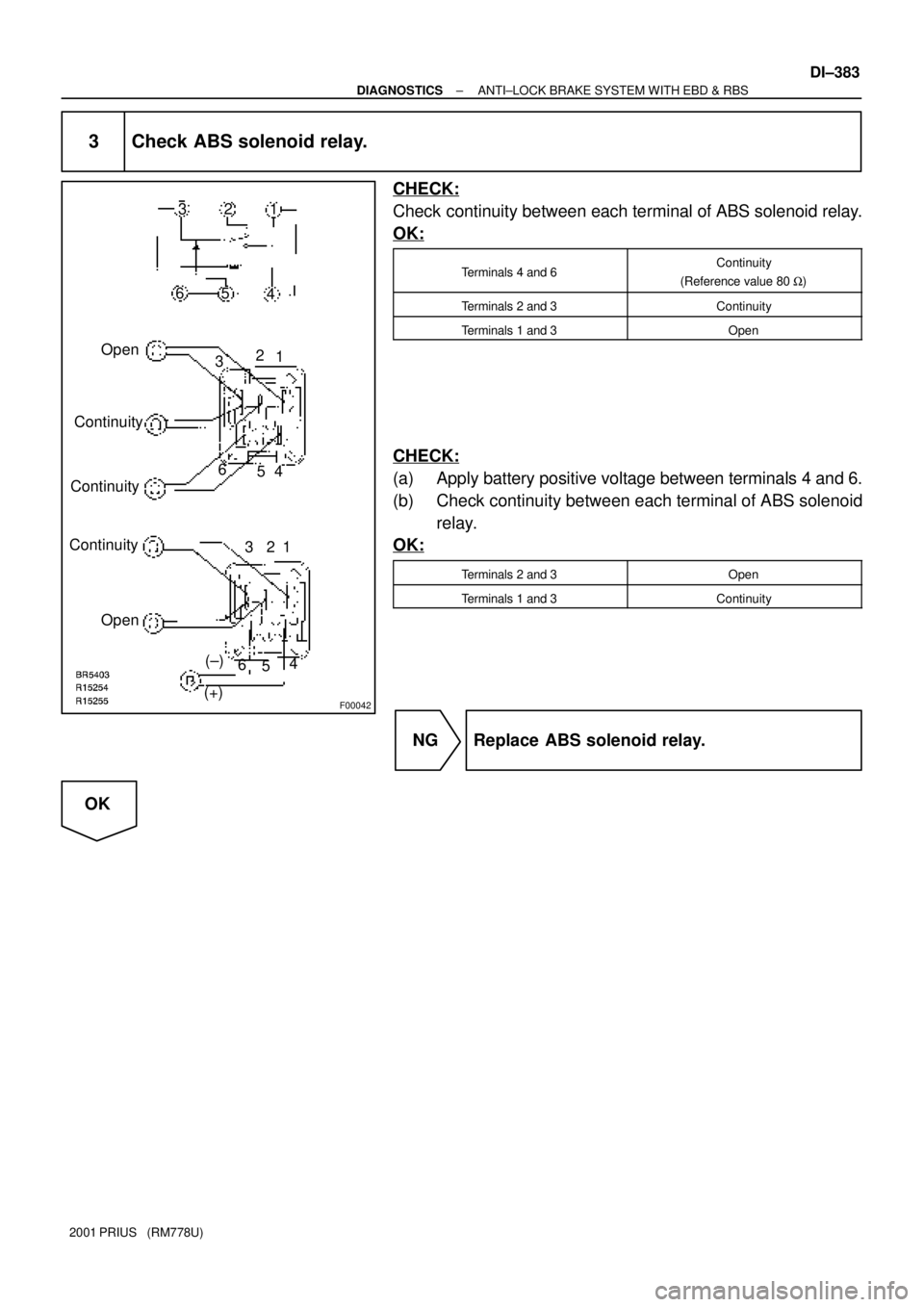
3 Check ABS solenoid relay.
CHECK:
Check continuity between each terminal of ABS solenoid relay.
OK:
Terminals 4 and 6Continuity
(Reference value 80 W)
Terminals 2 and 3Continuity
Terminals 1 and 3Open
CHECK:
(a) Apply battery positive voltage between terminals 4 and 6.
(b) Check continuity between each terminal of ABS solenoid
relay.
OK:
Terminals 2 and 3Open
Terminals 1 and 3Continuity
NG Replace ABS solenoid relay.
OK
Page 962 of 1943
F12443
ABS Solenoid
RelayEngine Room R/B
No. 3
Brake
Actuator
Brake ECU
ASTBS3
ASTAST
DI±384
± DIAGNOSTICSANTI±LOCK BRAKE SYSTEM WITH EBD & RBS
2001 PRIUS (RM778U)
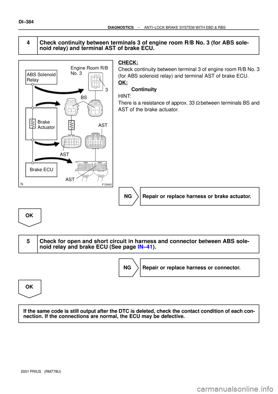
4 Check continuity between terminals 3 of engine room R/B No. 3 (for ABS sole-
noid relay) and terminal AST of brake ECU.
CHECK:
Check continuity between terminal 3 of engine room R/B No. 3
(for ABS solenoid relay) and terminal AST of brake ECU.
OK:
Continuity
HINT:
There is a resistance of approx. 33 W between terminals BS and
AST of the brake actuator.
NG Repair or replace harness or brake actuator.
OK
5 Check for open and short circuit in harness and connector between ABS sole-
noid relay and brake ECU (See page IN±41).
NG Repair or replace harness or connector.
OK
If the same code is still output after the DTC is deleted, check the contact condition of each con-
nection. If the connections are normal, the ECU may be defective.
Page 963 of 1943
F12673
B±G
F111
L4 Instrument
Panel J/B
DC/DC FL Block No. 1
3
Brake
Combination Meter
W±B
Brake Fluid
Level Warning
Switch7Brake ECU
LBL
C11
J7
J/C AM1162K
IE 2A
ID22B11
WR±Y
MAINLG±R
12
14
A W±G B±Y
IG1
RelayBRL
B12
C11
C10
C105 Body ECU
B8 B8
15
BR2
2 W±B
A A
J1
J/C AW±BInstrument
Panel J/B
Battery FL
Block
No. 21
F13
Ignition Switch
24
2H 2B 2D
2K2A 5 1
3 6
5 1
3
27
8GAUGE
LMultiplex Communication Circuit
IH 2B 6 1
J11
J/CGR±B GR
± DIAGNOSTICSANTI±LOCK BRAKE SYSTEM WITH EBD & RBS
DI±385
2001 PRIUS (RM778U)
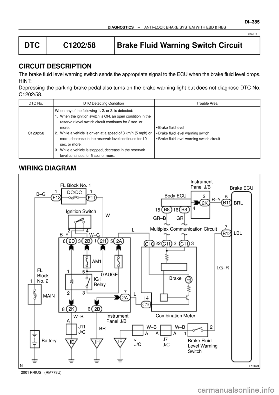
DTC C1202/58 Brake Fluid Warning Switch Circuit
CIRCUIT DESCRIPTION
The brake fluid level warning switch sends the appropriate signal to the ECU when the brake fluid level drops.
HINT:
Depressing the parking brake pedal also turns on the brake warning light but does not diagnose DTC No.
C1202/58.
DTC No.DTC Detecting ConditionTrouble Area
C1202/58
When any of the following 1. 2. or 3. is detected:
1. When the ignition switch is ON, an open condition in the
reservoir level switch circuit continues for 2 sec. or
more.
2. While a vehicle is driven at a speed of 3 km/h (5 mph) or
more, decrease in the reservoir level continues for 10
sec. or more.
3. While a vehicle is stopped, decrease in the reservoir
level continues for 5 sec. or more.
�Brake fluid level
�Brake fluid level warning switch
�Brake fluid level warning switch circuit
WIRING DIAGRAM
DI1GZ±10
Page 964 of 1943
DI±386
± DIAGNOSTICSANTI±LOCK BRAKE SYSTEM WITH EBD & RBS
2001 PRIUS (RM778U)
INSPECTION PROCEDURE
1 Check brake fluid level.
CHECK:
Check the amount of fluid in the brake reservoir.
NG Check and repair brake fluid leakage and add
fluid.
OK
2 Check brake fluid level warning switch (See page BE±2).
NG Replace brake fluid level warning switch.
OK
3 Check for open circuit in all the harness and components connected to brake
fluid level warning light (See page IN±41).
NG Repair or replace harness or connector.
OK
Check and replace brake ECU.
Page 965 of 1943
F12674
B3Brake ECU
Brake Actuator
B3
B3
B3B13
B13
B13
B13 2
1
8
71
8
7 16
V P LGL
SLA+
SLA±
SLR+
SLR±
± DIAGNOSTICSANTI±LOCK BRAKE SYSTEM WITH EBD & RBS
DI±387
2001 PRIUS (RM778U)
DTCC1211/61, C1212/62Linear Solenoid Circuit
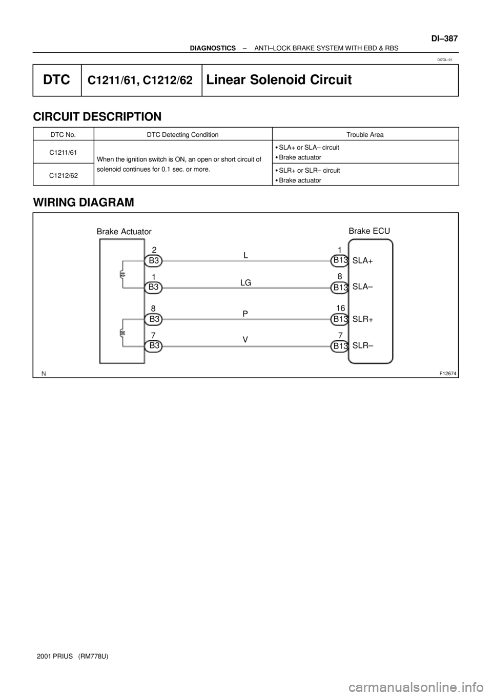
CIRCUIT DESCRIPTION
DTC No.DTC Detecting ConditionTrouble Area
C1211/61When the ignition switch is ON, an open or short circuit of
�SLA+ or SLA± circuit
�Brake actuator
C1212/62
When the ignition switch is ON, an oen or short circuit of
solenoid continues for 0.1 sec. or more.�SLR+ or SLR± circuit
�Brake actuator
WIRING DIAGRAM
DI7OL±01
Page 966 of 1943
F10936
SLA+
SLR+
SLR±
SLA±
B3
DI±388
± DIAGNOSTICSANTI±LOCK BRAKE SYSTEM WITH EBD & RBS
2001 PRIUS (RM778U)
INSPECTION PROCEDURE
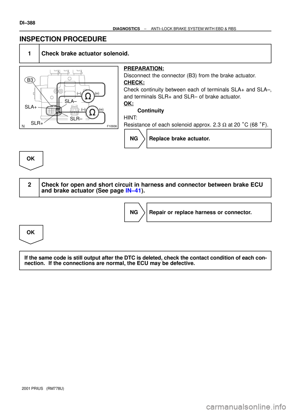
1 Check brake actuator solenoid.
PREPARATION:
Disconnect the connector (B3) from the brake actuator.
CHECK:
Check continuity between each of terminals SLA+ and SLA±,
and terminals SLR+ and SLR± of brake actuator.
OK:
Continuity
HINT:
Resistance of each solenoid approx. 2.3 W at 20 °C (68 °F).
NG Replace brake actuator.
OK
2 Check for open and short circuit in harness and connector between brake ECU
and brake actuator (See page IN±41).
NG Repair or replace harness or connector.
OK
If the same code is still output after the DTC is deleted, check the contact condition of each con-
nection. If the connections are normal, the ECU may be defective.
Page 967 of 1943
F12675
V
22 1424
16
R
W±B LG
AHVI± Brake ECU
HV ECU
J11
J/C
IDA(Shielded)
B11 B11 B11 B11 HVI+
HVO+
HVO± HTB+
HTB±
BTH± BTH+H14
H14
H14
H14G (Shielded)
W±B
A AJ10
J/C W±B 20
30
18
17
± DIAGNOSTICSANTI±LOCK BRAKE SYSTEM WITH EBD & RBS
DI±389
2001 PRIUS (RM778U)
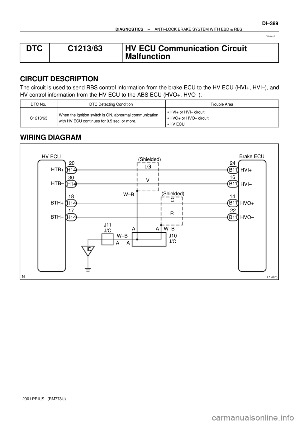
DTC C1213/63 HV ECU Communication Circuit
Malfunction
CIRCUIT DESCRIPTION
The circuit is used to send RBS control information from the brake ECU to the HV ECU (HVI+, HVI±), and
HV control information from the HV ECU to the ABS ECU (HVO+, HVO±).
DTC No.DTC Detecting ConditionTrouble Area
C1213/63When the ignition switch is ON, abnormal communication
with HV ECU continues for 0.5 sec. or more.�HVI+ or HVI± circuit
�HVO+ or HVO± circuit
�HV ECU
WIRING DIAGRAM
DI1H0±10
Page 968 of 1943
DI±390
± DIAGNOSTICSANTI±LOCK BRAKE SYSTEM WITH EBD & RBS
2001 PRIUS (RM778U)
INSPECTION PROCEDURE
1 Check for open and short circuit in harness and connector between terminals
HVI+, HVI±, HVO+ and HVO± of brake ECU and HV ECU (See page IN±41).
NG Repair or replace harness or connector.
OK
Check and replace HV ECU or brake ECU.
Page 969 of 1943
F12676
B±G
F101
3 Engine Room R/B No. 3
DC/DC FL Block No. 1
7Brake ECU
L W22
+BS
B13
8 ABS No. 4
1
F13
Battery2
B3 1
8 1
7 B3
B3
B3B13
B13
B13 B13
LG
P
V1
16 L
3
1
2
FL
Block
No. 2
Brake ActuatorSLA+
SLA±
SLR+
SLR± MAIN DI±392
± DIAGNOSTICSANTI±LOCK BRAKE SYSTEM WITH EBD & RBS
2001 PRIUS (RM778U)
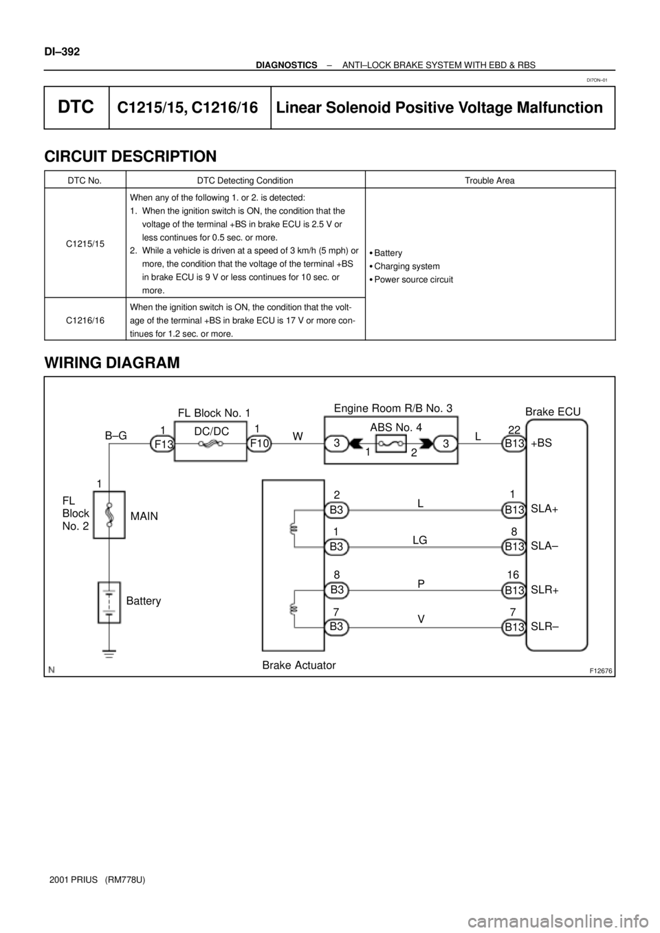
DTCC1215/15, C1216/16 Linear Solenoid Positive Voltage Malfunction
CIRCUIT DESCRIPTION
DTC No.DTC Detecting ConditionTrouble Area
C1215/15
When any of the following 1. or 2. is detected:
1. When the ignition switch is ON, the condition that the
voltage of the terminal +BS in brake ECU is 2.5 V or
less continues for 0.5 sec. or more.
2. While a vehicle is driven at a speed of 3 km/h (5 mph) or
more, the condition that the voltage of the terminal +BS
in brake ECU is 9 V or less continues for 10 sec. or
more.
�Battery
�Charging system
�Power source circuit
C1216/16
When the ignition switch is ON, the condition that the volt-
age of the terminal +BS in brake ECU is 17 V or more con-
tinues for 1.2 sec. or more.
WIRING DIAGRAM
DI7ON±01
Page 970 of 1943
F12445
Engine Room R/B No. 3
ABS No. 4
± DIAGNOSTICSANTI±LOCK BRAKE SYSTEM WITH EBD & RBS
DI±393
2001 PRIUS (RM778U)
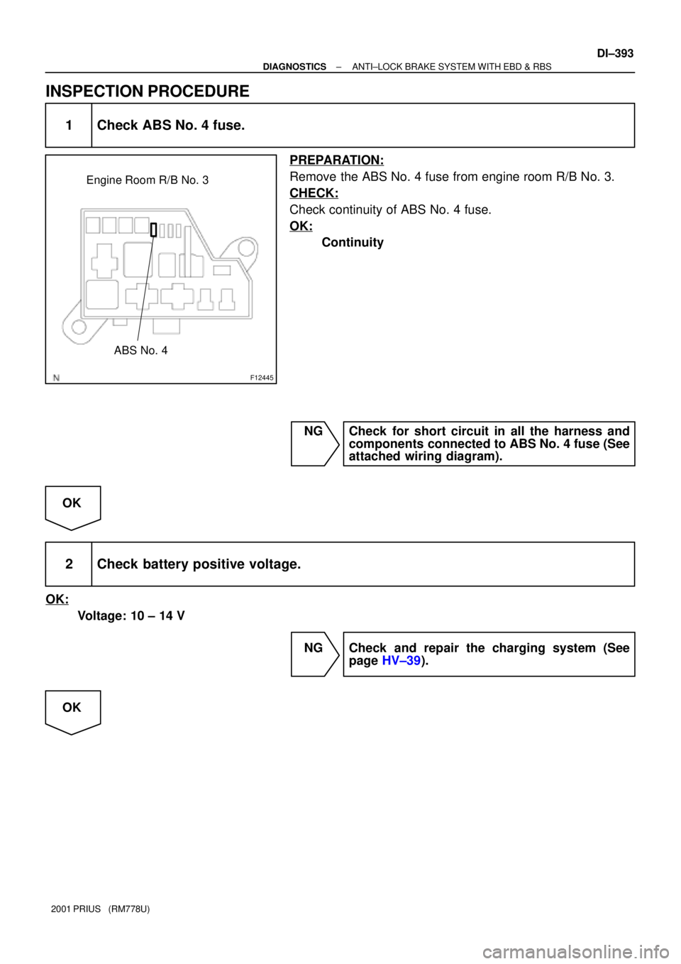
INSPECTION PROCEDURE
1 Check ABS No. 4 fuse.
PREPARATION:
Remove the ABS No. 4 fuse from engine room R/B No. 3.
CHECK:
Check continuity of ABS No. 4 fuse.
OK:
Continuity
NG Check for short circuit in all the harness and
components connected to ABS No. 4 fuse (See
attached wiring diagram).
OK
2 Check battery positive voltage.
OK:
Voltage: 10 ± 14 V
NG Check and repair the charging system (See
page HV±39).
OK
Trending: oil filter, lug pattern, USB port, page 590, tire size, Combustion, fuel cap
