TOYOTA RAV4 2006 Service Repair Manual
Manufacturer: TOYOTA, Model Year: 2006, Model line: RAV4, Model: TOYOTA RAV4 2006Pages: 2000, PDF Size: 45.84 MB
Page 1071 of 2000
U151E AUTOMATIC TRANSAXLE – AUTOMATIC TRANSAXLE UNITAX–197
AX
34. REMOVE OVERDRIVE BRAKE GASKET
(a) Remove the 2 overdrive brake gaskets from the
transaxle case.
35. REMOVE FORWARD CLUTCH ASSEMBLY
(a) Remove the forward clutch from the transaxle case.
(b) Remove the thrust needle roller bearing from the
forward clutch.
36. REMOVE MULTIPLE DISC CLUTCH HUB
(a) Remove the thrust needle roller bearing, multiple
disc clutch hub, thrust needle roller bearing and No.
1 thrust bearing race from the transaxle case.
37. INSPECT MULTIPLE DISC CLUTCH HUB (See page
AX-209)
38. REMOVE UNDERDRIVE PLANETARY GEAR
ASSEMBLY
(a) Remove the bolt and pawl shaft clamp.
D003573E01
D003574E03
D003906E02
D026787E07
D003576E03
Page 1072 of 2000
AX–198U151E AUTOMATIC TRANSAXLE – AUTOMATIC TRANSAXLE UNIT
AX
(b) Remove the parking lock pawl shaft.
(c) Push the parking lock pawl.
HINT:
Failure to do so will cause interference when the
underdrive planetary gear is removed.
(d) Remove the underdrive planetary gear from the
transaxle case.
NOTICE:
Make sure that the underdrive planetary gear
dose not fall out.
39. REMOVE PARKING LOCK PAWL
(a) Remove the spring, pawl pin and parking lock pawl.
40. REMOVE UNDERDRIVE CLUTCH ASSEMBLY
(a) Remove the underdrive clutch, thrust bearing and
bearing race from the transaxle case.
D009652E01
D009689E01
D003579E04
D026386E01
D003580E02
Page 1073 of 2000
U151E AUTOMATIC TRANSAXLE – AUTOMATIC TRANSAXLE UNITAX–199
AX
41. REMOVE UNDERDRIVE 1-WAY CLUTCH ASSEMBLY
(a) Using a screwdriver, remove the snap ring from the
transaxle case.
NOTICE:
Do not apply excessive force when removing
the snap ring.
(b) Remove the underdrive 1-way clutch from the
transaxle case.
(c) Remove the outer race retainer from the 1-way
clutch.
42. REMOVE NO. 2 UNDERDRIVE CLUTCH DISC
(a) Using a screwdriver, remove the snap ring.
NOTICE:
Do not apply excessive force when removing
the snap ring.
(b) Remove the flange, 4 discs and 4 plates from the
transaxle case.
43. INSPECT NO. 2 UNDERDRIVE CLUTCH DISC (See
page AX-209)
D003581E02
D003627E03
D003907E02
D026466E02
D026385E02
Page 1074 of 2000
AX–200U151E AUTOMATIC TRANSAXLE – AUTOMATIC TRANSAXLE UNIT
AX
44. REMOVE TRANSAXLE REAR COVER SUB-
ASSEMBLY
(a) Remove the 11 bolts.
(b) Tap on the circumference of the rear cover with a
plastic hammer to remove the transaxle rear cover
from the transaxle case.
45. REMOVE NO. 1 TRANSAXLE CASE PLUG
(a) Remove the 4 plugs from the transaxle rear cover.
(b) Remove the 4 O-rings from the 4 plugs.
46. REMOVE REAR CLUTCH OIL SEAL RING OUTER
(a) Remove the 3 rear clutch oil seal rings from the
transaxle rear cover.
47. REMOVE NEEDLE ROLLER BEARING
(a) Using SST, remove the bearing from the transaxle
rear cover.
SST 09387-00041 (09387-01021, 09387-01030,
09387-01040)
48. REMOVE NO. 1 GOVERNOR APPLY GASKET
(a) Using a screwdriver, remove the 3 apply gaskets.
C136369
C138647
D026389E03
D026472E01
D026390E01
Page 1075 of 2000
U151E AUTOMATIC TRANSAXLE – AUTOMATIC TRANSAXLE UNITAX–201
AX
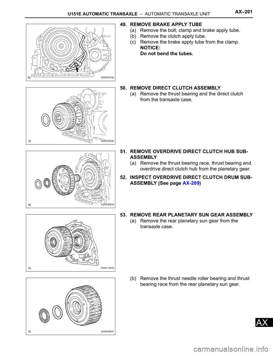
49. REMOVE BRAKE APPLY TUBE
(a) Remove the bolt, clamp and brake apply tube.
(b) Remove the clutch apply tube.
(c) Remove the brake apply tube from the clamp.
NOTICE:
Do not bend the tubes.
50. REMOVE DIRECT CLUTCH ASSEMBLY
(a) Remove the thrust bearing and the direct clutch
from the transaxle case.
51. REMOVE OVERDRIVE DIRECT CLUTCH HUB SUB-
ASSEMBLY
(a) Remove the thrust bearing race, thrust bearing and
overdrive direct clutch hub from the planetary gear.
52. INSPECT OVERDRIVE DIRECT CLUTCH DRUM SUB-
ASSEMBLY (See page AX-209)
53. REMOVE REAR PLANETARY SUN GEAR ASSEMBLY
(a) Remove the rear planetary sun gear from the
transaxle case.
(b) Remove the thrust needle roller bearing and thrust
bearing race from the rear planetary sun gear.
D026391E05
D026403E06
D026392E09
D026714E05
D026404E07
Page 1076 of 2000
AX–202U151E AUTOMATIC TRANSAXLE – AUTOMATIC TRANSAXLE UNIT
AX
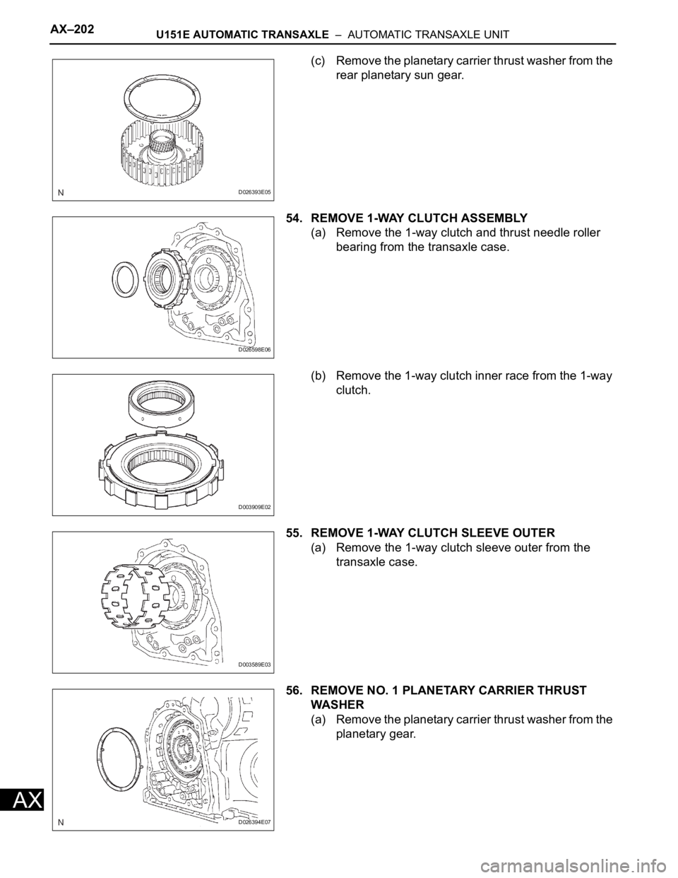
(c) Remove the planetary carrier thrust washer from the
rear planetary sun gear.
54. REMOVE 1-WAY CLUTCH ASSEMBLY
(a) Remove the 1-way clutch and thrust needle roller
bearing from the transaxle case.
(b) Remove the 1-way clutch inner race from the 1-way
clutch.
55. REMOVE 1-WAY CLUTCH SLEEVE OUTER
(a) Remove the 1-way clutch sleeve outer from the
transaxle case.
56. REMOVE NO. 1 PLANETARY CARRIER THRUST
WA S HE R
(a) Remove the planetary carrier thrust washer from the
planetary gear.
D026393E05
D026598E06
D003909E02
D003589E03
D026394E07
Page 1077 of 2000
U151E AUTOMATIC TRANSAXLE – AUTOMATIC TRANSAXLE UNITAX–203
AX
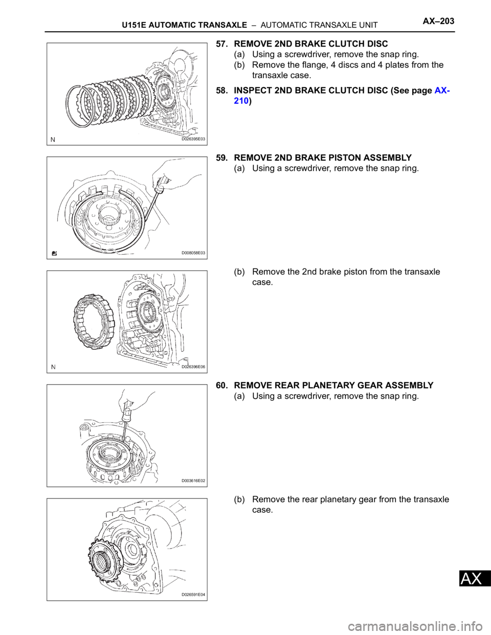
57. REMOVE 2ND BRAKE CLUTCH DISC
(a) Using a screwdriver, remove the snap ring.
(b) Remove the flange, 4 discs and 4 plates from the
transaxle case.
58. INSPECT 2ND BRAKE CLUTCH DISC (See page AX-
210)
59. REMOVE 2ND BRAKE PISTON ASSEMBLY
(a) Using a screwdriver, remove the snap ring.
(b) Remove the 2nd brake piston from the transaxle
case.
60. REMOVE REAR PLANETARY GEAR ASSEMBLY
(a) Using a screwdriver, remove the snap ring.
(b) Remove the rear planetary gear from the transaxle
case.
D026395E03
D008058E03
D026396E06
D003616E02
D026591E04
Page 1078 of 2000
AX–204U151E AUTOMATIC TRANSAXLE – AUTOMATIC TRANSAXLE UNIT
AX
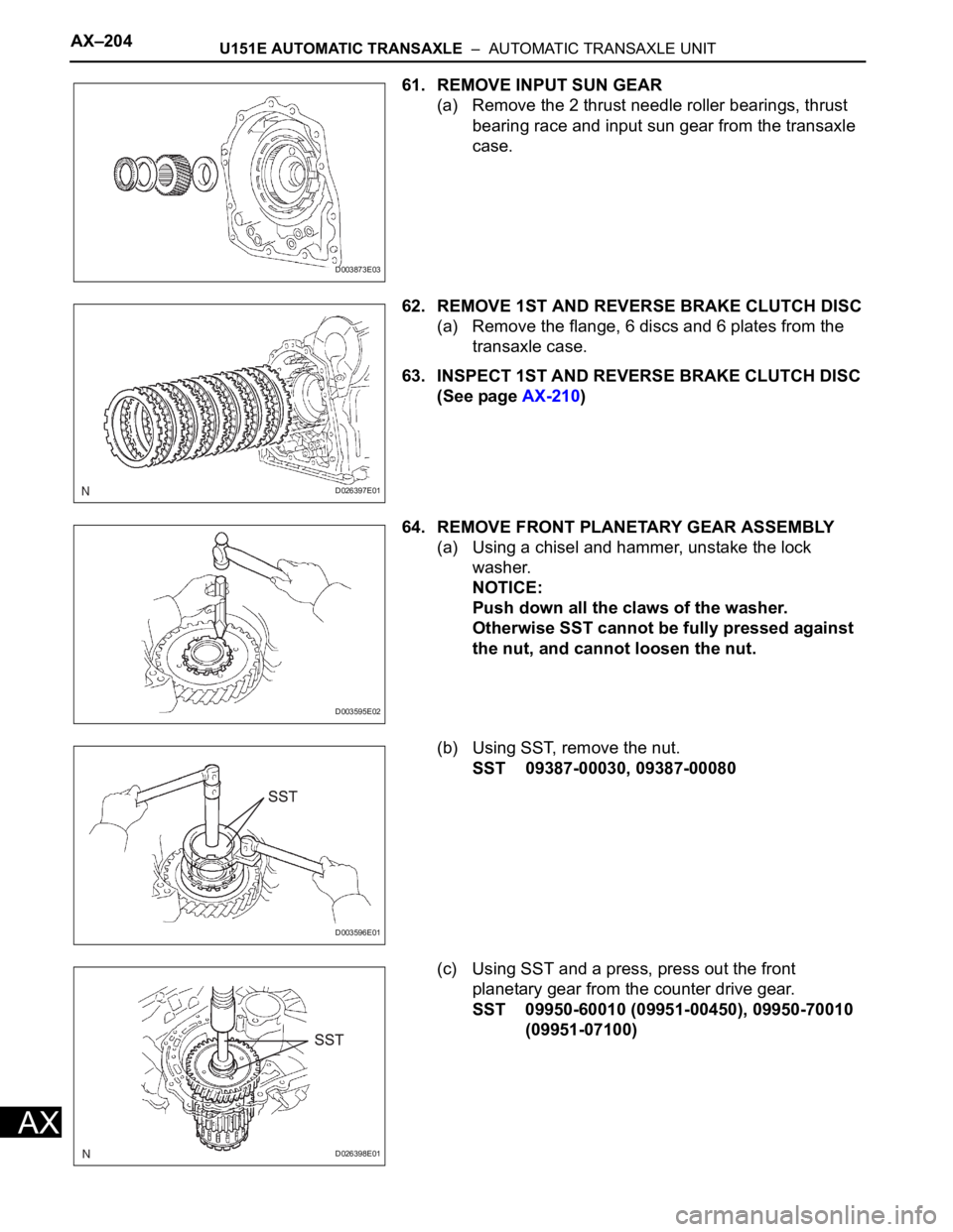
61. REMOVE INPUT SUN GEAR
(a) Remove the 2 thrust needle roller bearings, thrust
bearing race and input sun gear from the transaxle
case.
62. REMOVE 1ST AND REVERSE BRAKE CLUTCH DISC
(a) Remove the flange, 6 discs and 6 plates from the
transaxle case.
63. INSPECT 1ST AND REVERSE BRAKE CLUTCH DISC
(See page AX-210)
64. REMOVE FRONT PLANETARY GEAR ASSEMBLY
(a) Using a chisel and hammer, unstake the lock
washer.
NOTICE:
Push down all the claws of the washer.
Otherwise SST cannot be fully pressed against
the nut, and cannot loosen the nut.
(b) Using SST, remove the nut.
SST 09387-00030, 09387-00080
(c) Using SST and a press, press out the front
planetary gear from the counter drive gear.
SST 09950-60010 (09951-00450), 09950-70010
(09951-07100)
D003873E03
D026397E01
D003595E02
D003596E01
D026398E01
Page 1079 of 2000
U151E AUTOMATIC TRANSAXLE – AUTOMATIC TRANSAXLE UNITAX–205
AX
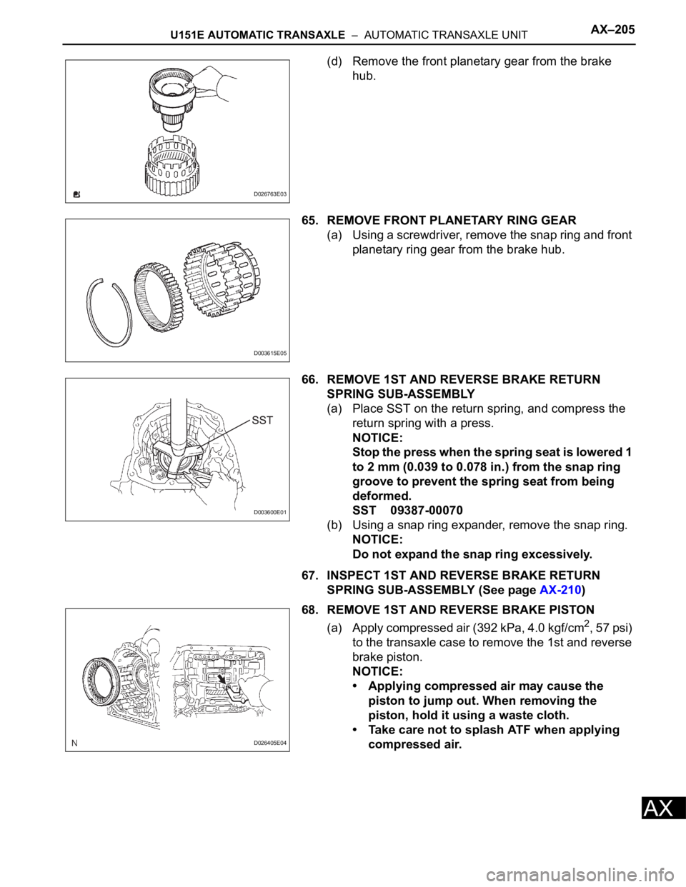
(d) Remove the front planetary gear from the brake
hub.
65. REMOVE FRONT PLANETARY RING GEAR
(a) Using a screwdriver, remove the snap ring and front
planetary ring gear from the brake hub.
66. REMOVE 1ST AND REVERSE BRAKE RETURN
SPRING SUB-ASSEMBLY
(a) Place SST on the return spring, and compress the
return spring with a press.
NOTICE:
Stop the press when the spring seat is lowered 1
to 2 mm (0.039 to 0.078 in.) from the snap ring
groove to prevent the spring seat from being
deformed.
SST 09387-00070
(b) Using a snap ring expander, remove the snap ring.
NOTICE:
Do not expand the snap ring excessively.
67. INSPECT 1ST AND REVERSE BRAKE RETURN
SPRING SUB-ASSEMBLY (See page AX-210)
68. REMOVE 1ST AND REVERSE BRAKE PISTON
(a) Apply compressed air (392 kPa, 4.0 kgf/cm
2, 57 psi)
to the transaxle case to remove the 1st and reverse
brake piston.
NOTICE:
• Applying compressed air may cause the
piston to jump out. When removing the
piston, hold it using a waste cloth.
• Take care not to splash ATF when applying
compressed air.
D026763E03
D003615E05
D003600E01
D026405E04
Page 1080 of 2000
AX–206U151E AUTOMATIC TRANSAXLE – AUTOMATIC TRANSAXLE UNIT
AX
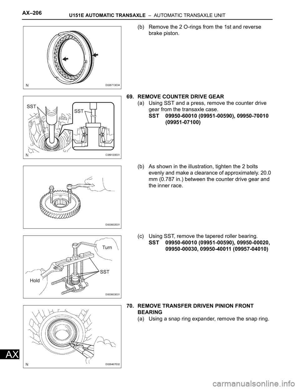
(b) Remove the 2 O-rings from the 1st and reverse
brake piston.
69. REMOVE COUNTER DRIVE GEAR
(a) Using SST and a press, remove the counter drive
gear from the transaxle case.
SST 09950-60010 (09951-00590), 09950-70010
(09951-07100)
(b) As shown in the illustration, tighten the 2 bolts
evenly and make a clearance of approximately. 20.0
mm (0.787 in.) between the counter drive gear and
the inner race.
(c) Using SST, remove the tapered roller bearing.
SST 09950-60010 (09951-00590), 09950-00020,
09950-00030, 09950-40011 (09957-04010)
70. REMOVE TRANSFER DRIVEN PINION FRONT
BEARING
(a) Using a snap ring expander, remove the snap ring.
D026713E04
C089120E01
D003602E01
D003603E01
D026467E02