relay TOYOTA RAV4 2006 Service Owner's Guide
[x] Cancel search | Manufacturer: TOYOTA, Model Year: 2006, Model line: RAV4, Model: TOYOTA RAV4 2006Pages: 2000, PDF Size: 45.84 MB
Page 1343 of 2000

GF1A TRANSFER – ACTIVE TORQUE CONTROL 4WD SYSTEMTF–15
TF
PROBLEM SYMPTOMS TABLE
HINT:
• Use the table below to help determine the cause of the
problem symptom. The potential causes of the symptoms
are listed in order of probability in the "Suspected area"
column of the table. Check each symptom by checking the
suspected areas in the order they are listed. Replace parts
as necessary.
• Inspect the fuses and relays related to this system before
inspecting the suspected areas below.
Active torque control 4WD system
HINT:
*:When driving 4WD mode, the vehicle is hard to turn, as if
the brakes were applied, due to the rotational difference
between the front and rear tires while turning.
Symptom Suspected area See page
Phenomenon of tight-corner braking*1.Steering angle sensor circuitTF-27
2.Linear solenoid circuitTF-30
3.4WD control ECU
4WD indicator light remains ON 4WD indicator light circuitTF-36
4WD indicator light does not come ON 4WD indicator light circuitTF-40
The system is in the DTC output mode although
terminals TC and CG of the DLC3 are not short
circuited1.TC and CG terminal circuitTF-42
2.4WD indicator light circuit
The system is not in the DTC output mode although
terminals TC and CG of the DLC3 are not short
circuited1.TC and CG terminal circuitTF-42
2.4WD indicator light circuit
Page 1490 of 2000

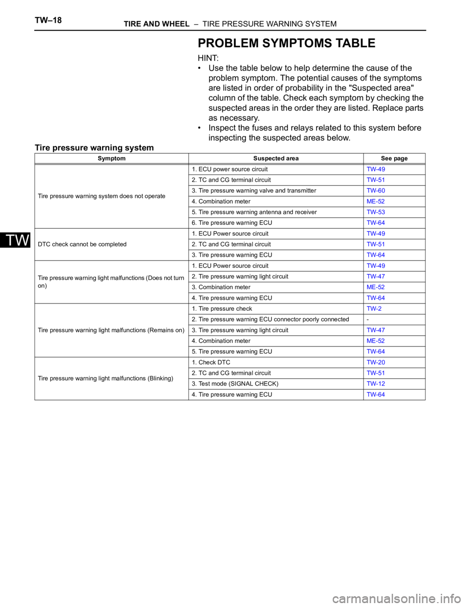
TW–18TIRE AND WHEEL – TIRE PRESSURE WARNING SYSTEM
TW
PROBLEM SYMPTOMS TABLE
HINT:
• Use the table below to help determine the cause of the
problem symptom. The potential causes of the symptoms
are listed in order of probability in the "Suspected area"
column of the table. Check each symptom by checking the
suspected areas in the order they are listed. Replace parts
as necessary.
• Inspect the fuses and relays related to this system before
inspecting the suspected areas below.
Tire pressure warning system
Symptom Suspected area See page
Tire pressure warning system does not operate1. ECU power source circuitTW-49
2. TC and CG terminal circuitTW-51
3. Tire pressure warning valve and transmitterTW-60
4. Combination meterME-52
5. Tire pressure warning antenna and receiverTW-53
6. Tire pressure warning ECUTW-64
DTC check cannot be completed1. ECU Power source circuitTW-49
2. TC and CG terminal circuitTW-51
3. Tire pressure warning ECUTW-64
Tire pressure warning light malfunctions (Does not turn
on)1. ECU Power source circuitTW-49
2. Tire pressure warning light circuitTW-47
3. Combination meterME-52
4. Tire pressure warning ECUTW-64
Tire pressure warning light malfunctions (Remains on)1. Tire pressure checkTW-2
2. Tire pressure warning ECU connector poorly connected -
3. Tire pressure warning light circuitTW-47
4. Combination meterME-52
5. Tire pressure warning ECUTW-64
Tire pressure warning light malfunctions (Blinking)1. Check DTCTW-20
2. TC and CG terminal circuitTW-51
3. Test mode (SIGNAL CHECK)TW-12
4. Tire pressure warning ECUTW-64
Page 1522 of 2000

BRAKE CONTROL – VEHICLE STABILITY CONTROL SYSTEMBC–19
BC
4. FAIL SAFE FUNCTION
(a) When a failure occurs in the ABS with BA, TRC and
VSC systems, the ABS and VSC warning lights
illuminate, the slip indicator light comes on*1 or
remains off*2, and the operations of those systems
are prohibited. In addition to this, when a failure
which disables the EBD operation occurs, the brake
warning light comes on and its operation is
prohibited.
HINT:
*1: for 2WD
*2: for 4WD
(b) If control is prohibited due to a malfunction during
operation, control is disabled gradually to avoid
sudden vehicle instability.
5. INITIAL CHECK
(a) When the vehicle speed first reaches approximately
6 km/h (4 mph) or more after the ignition switch is
turned ON, each solenoid valve and the motor of the
ABS and TRACTION actuator are sequentially
activated to perform electrical checks. During the
initial check, the operating sound of the solenoid
valve and motor can be heard from the engine
compartment, but this does not indicate a
malfunction.
6. SERVICE MODE
(a) VSC operation can be disabled by operating the
intelligent tester.
HINT:
Refer to the intelligent tester operator's manual for
further details.
7. FUNCTION OF COMPONENTS
Components Functions
Speed Sensor
(Semiconductor Type)Detects the wheel speed and sends the signal to skid
control ECU
Skid Control ECU
(Housed in ABS and TRACTION Actuator)• Processes the signals from each sensor to control the
ABS, BA, TRC, and VSC
• Sends and receives control signals to and from the
ECM, yaw rate and deceleration sensor, steering
sensor, etc. via CAN communication.
ABS and TRACTION Actuator • Consists of the master cylinder cut solenoid valve,
holding solenoid valve, pressure reduction solenoid
valve, pump motor, and reservoir, and adjusts the brake
fluid pressure applied to each wheel cylinder
• Houses the skid control ECU
Solenoid Relay • Supplies power to each solenoid
• Housed in the skid control ECU
Motor Relay (VSC MTR Relay) • Supplies power to the pump motor
• Installed in engine room No. 1 relay block
Fail-safe Relay (VSC FAIL Relay) • Cuts off power to the motor when the pump motor circuit
malfunctions
• Installed in engine room No. 1 relay block
Page 1545 of 2000

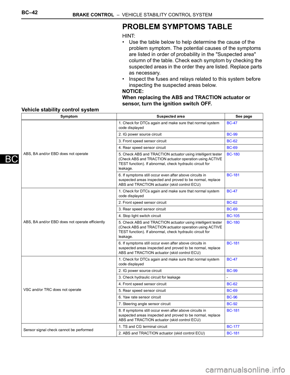
BC–42BRAKE CONTROL – VEHICLE STABILITY CONTROL SYSTEM
BC
PROBLEM SYMPTOMS TABLE
HINT:
• Use the table below to help determine the cause of the
problem symptom. The potential causes of the symptoms
are listed in order of probability in the "Suspected area"
column of the table. Check each symptom by checking the
suspected areas in the order they are listed. Replace parts
as necessary.
• Inspect the fuses and relays related to this system before
inspecting the suspected areas below.
NOTICE:
When replacing the ABS and TRACTION actuator or
sensor, turn the ignition switch OFF.
Vehicle stability control system
Symptom Suspected area See page
ABS, BA and/or EBD does not operate1. Check for DTCs again and make sure that normal system
code displayedBC-47
2. IG power source circuitBC-99
3. Front speed sensor circuitBC-62
4. Rear speed sensor circuitBC-69
5. Check ABS and TRACTION actuator using intelligent tester
(Check ABS and TRACTION actuator operation using ACTIVE
TEST function). If abnormal, check hydraulic circuit for
leakage.BC-180
6. If symptoms still occur even after above circuits in
suspected areas inspected and proved to be normal, replace
ABS and TRACTION actuator (skid control ECU)BC-181
ABS, BA and/or EBD does not operate efficiently1. Check for DTCs again and make sure that normal system
code displayedBC-47
2. Front speed sensor circuitBC-62
3. Rear speed sensor circuitBC-69
4. Stop light switch circuitBC-105
5. Check ABS and TRACTION actuator using intelligent tester
(Check ABS and TRACTION actuator operation using ACTIVE
TEST function). If abnormal, check hydraulic circuit for
leakage.BC-180
6. If symptoms still occur even after above circuits in
suspected areas inspected and proved to be normal, replace
ABS and TRACTION actuator (skid control ECU)BC-181
VSC and/or TRC does not operate1. Check for DTCs again and make sure that normal system
code displayedBC-47
2. IG power source circuitBC-99
3. Check hydraulic circuit for leakage -
4. Front speed sensor circuitBC-62
5. Rear speed sensor circuitBC-69
6. Yaw rate sensor circuitBC-96
7. Steering angle sensor circuitBC-92
8. If symptoms still occur even after above circuits in
suspected areas inspected and proved to be normal, replace
ABS and TRACTION actuator (skid control ECU)BC-181
Sensor signal check cannot be performed1. TS and CG terminal circuitBC-177
2. ABS and TRACTION actuator (skid control ECU)BC-181
Page 1547 of 2000

BC–44BRAKE CONTROL – VEHICLE STABILITY CONTROL SYSTEM
BC
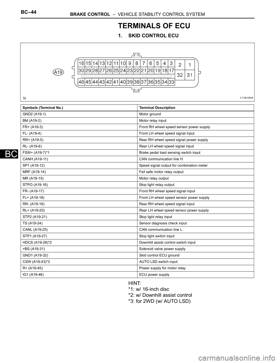
TERMINALS OF ECU
1. SKID CONTROL ECU
HINT:
*1: w/ 16-inch disc
*2: w/ Downhill assist control
*3: for 2WD (w/ AUTO LSD)
Symbols (Terminal No.) Terminal Description
GND2 (A19-1) Motor ground
BM (A19-2) Motor relay input
FR+ (A19-3) Front RH wheel speed sensor power supply
FL- (A19-4) Front LH wheel speed signal input
RR+ (A19-5) Rear RH wheel speed signal power supply
RL- (A19-6) Rear LH wheel speed signal input
FSW+ (A19-7)*1 Brake pedal load sensing switch input
CANH (A19-11) CAN communication line H
SP1 (A19-12) Speed signal output for combination meter
MRF (A19-14) Fail safe motor relay output
MR (A19-15) Motor relay output
STPO (A19-16) Stop light relay output
FR- (A19-17) Front RH wheel speed signal input
FL+ (A19-18) Front LH wheel speed sensor power supply
RR- (A19-19) Rear RH wheel speed signal input
RL+ (A19-20) Rear LH wheel speed sensor power supply
STP2 (A19-21) Stop light relay input
TS (A19-24) Sensor diagnosis check input
CANL (A19-25) CAN communication line L
STP1 (A19-27) Stop light switch input
HDCS (A19-28)*2 Downhill assist control switch input
+BS (A19-31) Solenoid valve power supply
GND1 (A19-32) Skid control ECU ground
CSW (A19-43)*3 AUTO LSD switch input
R+ (A19-45) Power supply for motor relay
IG1 (A19-46) ECU power supply
C110610E04
Page 1548 of 2000

BRAKE CONTROL – VEHICLE STABILITY CONTROL SYSTEMBC–45
BC
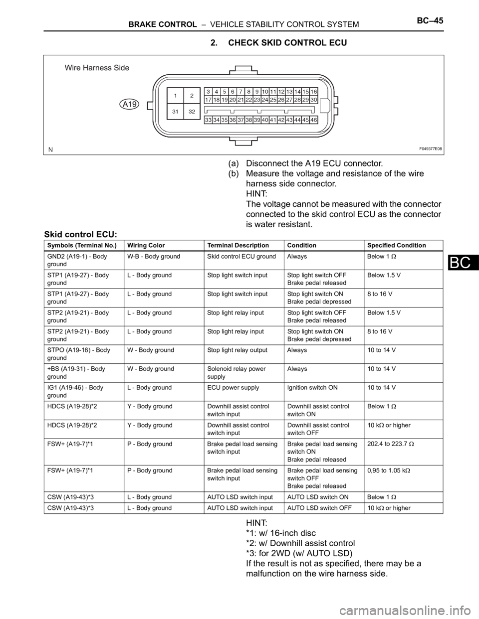
2. CHECK SKID CONTROL ECU
(a) Disconnect the A19 ECU connector.
(b) Measure the voltage and resistance of the wire
harness side connector.
HINT:
The voltage cannot be measured with the connector
connected to the skid control ECU as the connector
is water resistant.
Skid control ECU:
HINT:
*1: w/ 16-inch disc
*2: w/ Downhill assist control
*3: for 2WD (w/ AUTO LSD)
If the result is not as specified, there may be a
malfunction on the wire harness side.
F049377E08
Symbols (Terminal No.) Wiring Color Terminal Description ConditionSpecified Condition
GND2 (A19-1) - Body
groundW-B - Body ground Skid control ECU ground Always Below 1
STP1 (A19-27) - Body
groundL - Body ground Stop light switch input Stop light switch OFF
Brake pedal releasedBelow 1.5 V
STP1 (A19-27) - Body
groundL - Body ground Stop light switch input Stop light switch ON
Brake pedal depressed8 to 16 V
STP2 (A19-21) - Body
groundL - Body ground Stop light relay input Stop light switch OFF
Brake pedal releasedBelow 1.5 V
STP2 (A19-21) - Body
groundL - Body ground Stop light relay input Stop light switch ON
Brake pedal depressed8 to 16 V
STPO (A19-16) - Body
groundW - Body ground Stop light relay output Always 10 to 14 V
+BS (A19-31) - Body
groundW - Body ground Solenoid relay power
supplyAlways 10 to 14 V
IG1 (A19-46) - Body
groundL - Body ground ECU power supply Ignition switch ON 10 to 14 V
HDCS (A19-28)*2 Y - Body ground Downhill assist control
switch inputDownhill assist control
switch ONBelow 1
HDCS (A19-28)*2 Y - Body ground Downhill assist control
switch inputDownhill assist control
switch OFF10 k or higher
FSW+ (A19-7)*1 P - Body ground Brake pedal load sensing
switch inputBrake pedal load sensing
switch ON
Brake pedal released202.4 to 223.7
FSW+ (A19-7)*1 P - Body ground Brake pedal load sensing
switch inputBrake pedal load sensing
switch OFF
Brake pedal released0,95 to 1.05 k
CSW (A19-43)*3 L - Body ground AUTO LSD switch input AUTO LSD switch ON Below 1
CSW (A19-43)*3 L - Body ground AUTO LSD switch input AUTO LSD switch OFF 10 k or higher
Page 1561 of 2000

BC–58BRAKE CONTROL – VEHICLE STABILITY CONTROL SYSTEM
BC
FR ABS STATUS FR wheel ABS control status / ON
or OFFON: During control -
FL ABS STATUS FL wheel ABS control status / ON
or OFFON: During control -
RR ABS STATUS RR wheel ABS control status / ON
or OFFON: During control -
RL ABS STATUS RL wheel ABS control status / ON
or OFFON: During control -
RR EBD STATUS RR wheel EBD control status /
ON or OFFON: During control -
RL EBD STATUS RL wheel EBD control status / ON
or OFFON: During control -
BA STATUS BA control status / ON or OFF ON: During control -
TRAC STATUS TRC control status / ON or OFF ON: During control -
TRAC ENG STATUS TRC engine control status / ON or
OFFON: During control -
TRAC BRK STATUS TRC brake control status / ON or
OFFON: During control -
FR VSC STATUS FR wheel VSC control status / ON
or OFFON: During control -
FL VSC STATUS FL wheel VSC control status / ON
or OFFON: During control -
RR VSC STATUS RR wheel VSC control status /
ON or OFFON: During control -
RL VSC STATUS RL wheel VSC control status / ON
or OFFON: During control -
ENG REVOLUTIONS Engine revolutions / min.: 0 r/min,
max.: 65535 r/min--
ENGINE TORQUE Real engine torque / min.: -1024
Nm, max.: 1023 Nm--
ACCELERATOR % Percentage of accelerator pedal
opening angle / min.: 0%, max.:
128%--
SOL RELAY Solenoid relay / ON or OFF ON: Solenoid relay ON
OFF: Solenoid relay OFF-
ELECTRONICALLY
CONTROLLED BRAKE SYSTEM
MTR RELAYElectronically Controlled Brake
System Motor relay (VSC1 relay)
/ ON or OFFON: Motor relay ON
OFF: Motor relay OFF-
FAIL MTR RELAY Fail-safe motor relay / ON or OFF ON: Motor relay ON
OFF: Motor relay OFF-
SM2 TRC / VSC solenoid (SM2) / ON
or OFFON: Operates -
SM1 TRC / VSC solenoid (SM1) / ON
or OFFON: Operates -
SFRH*1 ABS solenoid (SFRH) / ON or
OFFON: Operates
OFF: Does not operate-
SFRR*2 ABS solenoid (SFRR) / ON or
OFFON: Operates
OFF: Does not operate-
SFLH*3 ABS solenoid (SFLH) / ON or
OFFON: Operates
OFF: Does not operate-
SFLR*4 ABS solenoid (SFLR) / ON or
OFFON: Operates
OFF: Does not operate-
SRRH*5 ABS solenoid (SRRH) / ON or
OFFON: Operates
OFF: Does not operate-
SRRR*6 ABS solenoid (SRRR) / ON or
OFFON: Operates
OFF: Does not operate-
SRLH*7 ABS solenoid (SRLH) / ON or
OFFON: Operates
OFF: Does not operate- Tester Display Measurement Item/Range Normal Condition Diagnostic Note
Page 1563 of 2000

BC–60BRAKE CONTROL – VEHICLE STABILITY CONTROL SYSTEM
BC
2. PARFORM ACTIVE TEST
HINT:
Performing the intelligent tester's ACTIVE TEST allows
relay, VSV, actuator and other items to be operated
without removing any parts. Performing the ACTIVE
TEST early in troubleshooting is one way to save time.
The DATA LIST can be displayed during the ACTIVE
TEST.
(a) Connect the intelligent tester (with CAN VIM) to the
DLC3.
(b) Turn the ignition switch ON.
(c) Turn the intelligent tester on.
(d) Perform the ACTIVE TEST according to the display
on the tester.
HINT:
• The ignition switch must be turned ON to
proceed to the ACTIVE TEST using the
intelligent tester.
• The ACTIVE TESTs of the ABS solenoid, ABS
motor relay, ABS warning light and BRAKE
warning light are available when the vehicle is
stopped.
• The motors stop automatically after 5 seconds of
activation to prevent them from being damaged.
When the motors are driven repeatedly, certain
intervals are required.
• Each solenoid stops automatically after 2
seconds of activation to prevent them from being
damaged, and can be operated again after a
certain interval.
• Do not depress the brake pedal while only the
pressure reduction solenoid valves are on.
• Do not drive 2 or more solenoids simultaneously
except to operate the pressure holding solenoid
valves and pressure reduction solenoid valves of
each wheel.
Skid control ECU
Tester Display Test Part Control Range
ABS WARN LAMP Turns ABS warning light ON / OFF Observe combination meter
VSC WARN LAMP Turns VSC warning light ON / OFF Observe combination meter
BRAKE WARN LAMP Turns Brake warning light ON / OFF Observe combination meter
SLIP INDI LAMP Turns Slip indicator light ON / OFF Observe combination meter
D-HILL LIGHT*1 Turns downhill assist control indicator light ON /
OFFObserve combination meter
AUTO LSD LAMP*2 Turns AUTO LSD indicator light ON / OFF Observe combination meter
BUZZER Turns skid control buzzer ON / OFF Buzzer can be heard
STP LAMP RELAY Turns stop light relay (BRK relay) ON / OFF Operation sound of motor can be heard
SOL RELAY Turns ABS solenoid relay ON / OFF -
MOTOR RELAY Turns ABS motor relay ON / OFF Operation sound of motor can be heard
SRLR Turns ABS solenoid (SRLR) ON / OFF Operation sound of solenoid (clicking sound)
can be heard
SRLH Turns ABS solenoid (SRLH) ON / OFF Operation sound of solenoid (clicking sound)
can be heard
Page 1616 of 2000

PS–16POWER STEERING – ELECTRONIC POWER STEERING SYSTEM
PS
FAIL-SAFE CHART
If a problem occurs in the electric power steering system, the
P/S warning light will come on in the combination meter and
steering power assist will be stopped, fixed at a particular
point, or decreased simultaneously to protect the system.
Electronic power steering system
HINT:
The amount of power assist may be decreased to prevent the
motor and ECUs from overheating if the steering wheel is
continuously turned when the vehicle is either stopped or
driven at a low speed, or if the steering wheel is kept at either
full lock position for a long time. In such cases, the amount of
power assist returns to normal if the steering wheel is not
turned for approximately 10 minutes with the engine idling.
DTC No. Detection Condition Fail-safe
C1511/11 Torque sensor malfunction Power assist stops
C1512/11
C1513/11
C1514/11
C1521/25 Motor malfunction
C1524/24
C1528/12 Motor rotation angle sensor malfunction
C1531/25 ECU malfunction
C1532/25
C1534/25
C1551/25 IG power source voltage error
C1552/22 PIG power source voltage error
C1554/23 Power source relay malfunction
C1555/25 Motor relay malfunction
C1533/25 ECU malfunction Assist force restricted
U0073/49 CAN bus malfunction Amount of power assist is locked at 140 km/h
(87.5 mph) level of power assist
U0121/42 Skid control ECU communication error
U0105/41 ECM communication error Power assist stops
Page 1618 of 2000

PS–18POWER STEERING – ELECTRONIC POWER STEERING SYSTEM
PS
2. PERFORM ACTIVE TEST
HINT:
Performing the intelligent tester's ACTIVE TEST allows
relays, the VSV, actuators and other items to be
operated without removing any parts. Performing the
ACTIVE TEST early in troubleshooting is one way to
save time. The DATA LIST can be displayed in the
ACTIVE TEST.
(a) Connect the intelligent tester (with CAN VIM) to the
DLC3.
(b) Turn the ignition switch ON and turn the intelligent
tester ON.
(c) Perform the ACTIVE TEST by following the prompts
on the tester.
Combination meter
MOTOR ROTATE Motor rotation angle:
Min.: 0
Max.: 360
Power steering in operation During steering operation, motor
rotation angle value changes from
0 to 360
MOTOR VOLTAGE Motor power supply voltage:
0 V
Max.: 45.955 VPower steering in operation -
MTR TERMINAL(U) Motor terminal voltage (U phase):
Min.: 0 V
Max.: 46.667 VSteering wheel is turned While turning the steering wheel,
a value within the range of 1 V to
approximately 0.7 V less than the
battery voltage is displayed. (The
value changes according to the
steering load.)
MTR TERMINAL(V) Motor terminal voltage (V phase):
Min.: 0 V
Max.: 46.667 VSteering wheel is turned While turning the steering wheel,
a value within the range of 1 V to
approximately 0.7 V less than the
battery voltage is displayed. (The
value changes according to the
steering load.)
MTR TERMINAL(W) Motor Terminal voltage (W
phase):
Min.: 0 V
Max.: 46.667 VSteering wheel is turned While turning the steering wheel,
a value within the range of 1 V to
approximately 0.7 V less than the
battery voltage is displayed. (The
value changes according to the
steering load.)
IG ON/OFF TIMES Ignition switch ON/OFF number
of times after fail detection:
Min.: 0 times
Max.: 65535 times--
# CODES Number of detected DTCs when
freeze frame data stored:
Min.: 0
Max.: 255 --
PS ASSIST SIG Power steering assist signal:
ON or OFF-- Tester Display Measurement Item/Range Normal Condition Reference Value
Tester Display Test Part Control Range
EPS INDIC P/S indicator
ON/OFFConfirm that vehicle is stopped, engine idling