relay TOYOTA RAV4 2006 Service Workshop Manual
[x] Cancel search | Manufacturer: TOYOTA, Model Year: 2006, Model line: RAV4, Model: TOYOTA RAV4 2006Pages: 2000, PDF Size: 45.84 MB
Page 1813 of 2000
CC–14CRUISE CONTROL – CRUISE CONTROL SYSTEM
CC
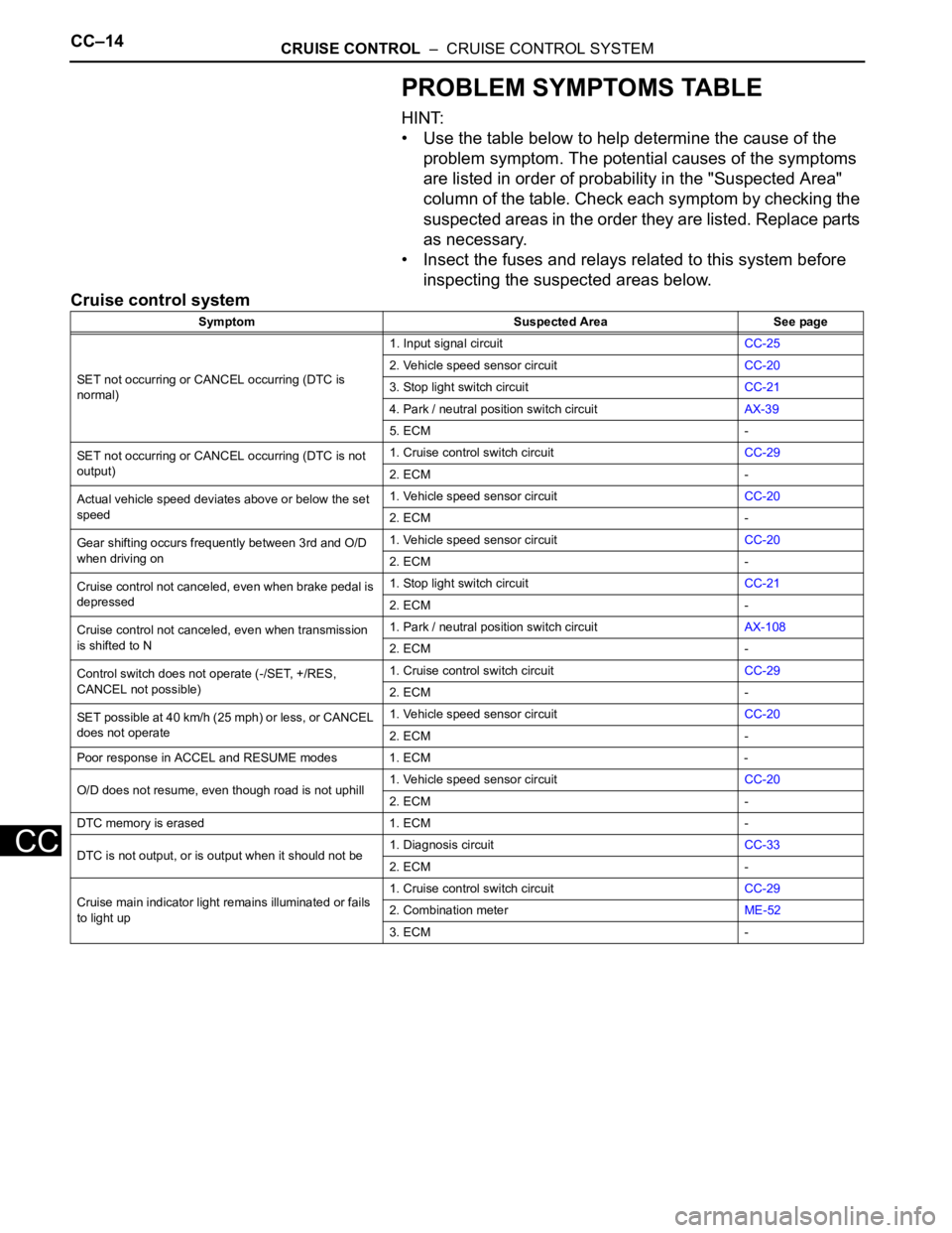
PROBLEM SYMPTOMS TABLE
HINT:
• Use the table below to help determine the cause of the
problem symptom. The potential causes of the symptoms
are listed in order of probability in the "Suspected Area"
column of the table. Check each symptom by checking the
suspected areas in the order they are listed. Replace parts
as necessary.
• Insect the fuses and relays related to this system before
inspecting the suspected areas below.
Cruise control system
Symptom Suspected Area See page
SET not occurring or CANCEL occurring (DTC is
normal)1. Input signal circuitCC-25
2. Vehicle speed sensor circuitCC-20
3. Stop light switch circuitCC-21
4. Park / neutral position switch circuitAX-39
5. ECM -
SET not occurring or CANCEL occurring (DTC is not
output)1. Cruise control switch circuitCC-29
2. ECM -
Actual vehicle speed deviates above or below the set
speed1. Vehicle speed sensor circuitCC-20
2. ECM -
Gear shifting occurs frequently between 3rd and O/D
when driving on1. Vehicle speed sensor circuitCC-20
2. ECM -
Cruise control not canceled, even when brake pedal is
depressed1. Stop light switch circuitCC-21
2. ECM -
Cruise control not canceled, even when transmission
is shifted to N1. Park / neutral position switch circuitAX-108
2. ECM -
Control switch does not operate (-/SET, +/RES,
CANCEL not possible)1. Cruise control switch circuitCC-29
2. ECM -
SET possible at 40 km/h (25 mph) or less, or CANCEL
does not operate1. Vehicle speed sensor circuitCC-20
2. ECM -
Poor response in ACCEL and RESUME modes 1. ECM -
O/D does not resume, even though road is not uphill1. Vehicle speed sensor circuitCC-20
2. ECM -
DTC memory is erased 1. ECM -
DTC is not output, or is output when it should not be1. Diagnosis circuitCC-33
2. ECM -
Cruise main indicator light remains illuminated or fails
to light up1. Cruise control switch circuitCC-29
2. Combination meterME-52
3. ECM -
Page 1818 of 2000

CRUISE CONTROL – CRUISE CONTROL SYSTEMCC–19
CC
(c) Clear the DTCs according to one of the following
procedures.
• Disconnect the negative (-) battery cable for
more than 1 minute.
• Remove the EFI NO. 1 and ETCS fuses from the
engine room relay block (located inside the
engine compartment) for more than 1 minute.
(d) Recheck for DTCs.
Page 1821 of 2000
CC–22CRUISE CONTROL – CRUISE CONTROL SYSTEM
CC
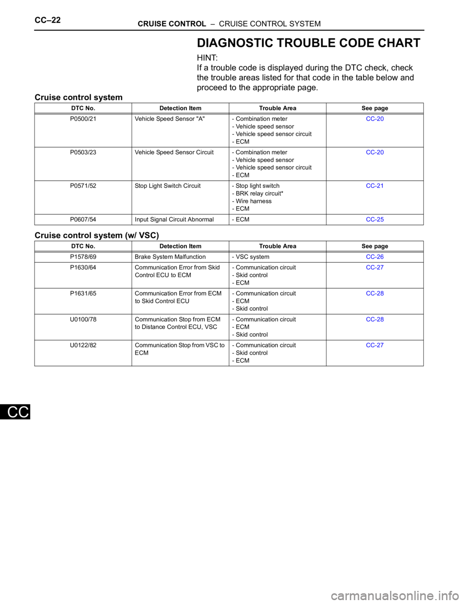
DIAGNOSTIC TROUBLE CODE CHART
HINT:
If a trouble code is displayed during the DTC check, check
the trouble areas listed for that code in the table below and
proceed to the appropriate page.
Cruise control system
Cruise control system (w/ VSC)
DTC No. Detection Item Trouble Area See page
P0500/21 Vehicle Speed Sensor "A" - Combination meter
- Vehicle speed sensor
- Vehicle speed sensor circuit
- ECMCC-20
P0503/23 Vehicle Speed Sensor Circuit - Combination meter
- Vehicle speed sensor
- Vehicle speed sensor circuit
- ECMCC-20
P0571/52 Stop Light Switch Circuit - Stop light switch
- BRK relay circuit*
- Wire harness
- ECMCC-21
P0607/54 Input Signal Circuit Abnormal - ECMCC-25
DTC No. Detection Item Trouble Area See page
P1578/69 Brake System Malfunction - VSC systemCC-26
P1630/64 Communication Error from Skid
Control ECU to ECM- Communication circuit
- Skid control
- ECMCC-27
P1631/65 Communication Error from ECM
to Skid Control ECU- Communication circuit
- ECM
- Skid controlCC-28
U0100/78 Communication Stop from ECM
to Distance Control ECU, VSC- Communication circuit
- ECM
- Skid controlCC-28
U0122/82 Communication Stop from VSC to
ECM- Communication circuit
- Skid control
- ECMCC-27
Page 1823 of 2000
CC–24CRUISE CONTROL – CRUISE CONTROL SYSTEM
CC
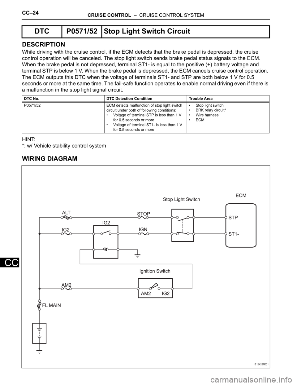
DESCRIPTION
While driving with the cruise control, if the ECM detects that the brake pedal is depressed, the cruise
control operation will be canceled. The stop light switch sends brake pedal status signals to the ECM.
When the brake pedal is not depressed, terminal ST1- is equal to the positive (+) battery voltage and
terminal STP is below 1 V. When the brake pedal is depressed, the ECM cancels cruise control operation.
The ECM outputs this DTC when the voltage of terminals ST1- and STP are both below 1 V for 0.5
seconds or more at the same time. The fail-safe function operates to enable normal driving even if there is
a malfunction in the stop light signal circuit.
HINT:
*: w/ Vehicle stability control system
WIRING DIAGRAM
DTC P0571/52 Stop Light Switch Circuit
DTC No. DTC Detection Condition Trouble Area
P0571/52 ECM detects malfunction of stop light switch
circuit under both of following conditions:
• Voltage of terminal STP is less than 1 V
for 0.5 seconds or more
• Voltage of terminal ST1- is less than 1 V
for 0.5 seconds or more• Stop light switch
• BRK relay circuit*
• Wire harness
•ECM
E124257E01
Page 1824 of 2000
CRUISE CONTROL – CRUISE CONTROL SYSTEMCC–25
CC
INSPECTION PROCEDURE
(a) Check the DATA LIST for proper functioning of the stop
light switch.
ECM
OK:
Display changes according to brake pedal
operation described in above table.
NG
OK
(a) Remove the STOP and IGN fuses from the instrument
panel junction block.
(b) Remove the IG2 fuse from the engine room No. 1 relay
block.
(c) Measure the resistance of the fuses.
Standard resistance:
Below 1
NG
OK
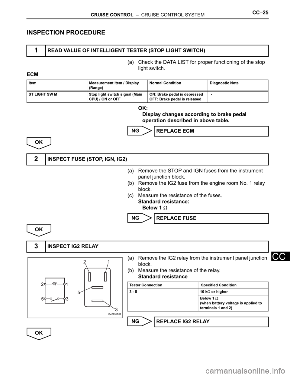
(a) Remove the IG2 relay from the instrument panel junction
block.
(b) Measure the resistance of the relay.
Standard resistance
NG
OK
1READ VALUE OF INTELLIGENT TESTER (STOP LIGHT SWITCH)
Item Measurement Item / Display
(Range) Normal Condition Diagnostic Note
ST LIGHT SW M Stop light switch signal (Main
CPU) / ON or OFF ON: Brake pedal is depressed
OFF: Brake pedal is released -
REPLACE ECM
2INSPECT FUSE (STOP, IGN, IG2)
REPLACE FUSE
3INSPECT IG2 RELAY
I045791E02
Tester Connection Specified Condition
3 - 5 10 k
or higher
Below 1
(when battery voltage is applied to
terminals 1 and 2)
REPLACE IG2 RELAY
Page 1839 of 2000

LI–8LIGHTING – LIGHTING SYSTEM
LI
*2: w/ Engine immobiliser system
(c) Manual light control system:
This system functions when lights such as the
headlights and taillights are illuminated by manual
operation of the light control switch.
(1) The main body ECU receives the following
signals (D).
• Light control switch signal
• Headlight dimmer switch signal
• Front fog light switch signal
(2) The main body ECU controls the following
signals based on the signals listed in D (E).
• Headlight relay operation signal
• Taillight relay operation signal
• Daytime running light No. 2 relay operation
signal
• Daytime running light No. 3 relay operation
signal
• Daytime running light No. 4 relay operation
signal
• Front fog light relay operation signal
(3) The main body ECU controls the on/off
operation of the following parts based on the
signals listed in E.
• Headlight (LOW)
• Headlight (HIGH)
• Side marker light (front and rear)
• Front fog light
(d) Light auto turn off system:
When the headlights and taillights are illuminated by
the operation of the light control switch, if the
ignition switch is turned OFF, this system continues
illuminating the headlights and taillights for
approximately 30 seconds, and then turns off the
lights. However, when all the doors are locked
manually, using the door lock button, using the key
or pressing LOCK on the transmitter turns the
headlights and taillights off immediately.
(1) The main body ECU receives the following
signals (F).
• Door courtesy switch signal
• Ignition switch signal
(2) The main body ECU controls the following
signals based on the signals listed in F (G).
• Headlight relay operation signal
• Taillight relay operation signal
• Daytime running light No. 2 relay operation
signal
• Daytime running light No. 3 relay operation
signal
• Daytime running light No. 4 relay operation
signal
• Front fog light relay operation signal
Page 1840 of 2000

LIGHTING – LIGHTING SYSTEMLI–9
LI
(3) The main body ECU controls the illumination
period of the following parts based on the
signals listed in G.
• Headlight (LOW)
• Headlight (HIGH)
• Side marker light (front and rear)
• Front fog light
(e) Daytime running light system:
This system is directly connected to the high-beam
headlights and is designed to automatically activate
the daytime running lights in order to increase the
visibility of the vehicle.
(1) The main body ECU receives the following (H).
• Ignition switch signal
• Engine speed
• Parking brake switch signal
• Light control switch signal
(2) The main body ECU controls the following signal
based on the signals listed in H (I).
• Daytime running light No. 2 relay operation
signal
(3) The main body ECU controls the on/off
operation of the following part based on the
signal listed in I.
• Headlight (HIGH)
Page 1846 of 2000
LIGHTING – LIGHTING SYSTEMLI–15
LI
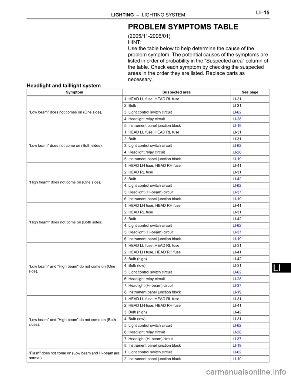
PROBLEM SYMPTOMS TABLE
(2005/11-2006/01)
HINT:
Use the table below to help determine the cause of the
problem symptom. The potential causes of the symptoms are
listed in order of probability in the "Suspected area" column of
the table. Check each symptom by checking the suspected
areas in the order they are listed. Replace parts as
necessary.
Headlight and taillight system
Symptom Suspected area See page
"Low beam" does not comes on (One side).1. HEAD LL fuse, HEAD RL fuse LI-31
2. Bulb LI-31
3. Light control switch circuitLI-62
4. Headlight relay circuitLI-28
5. Instrument panel junction blockLI-19
"Low beam" does not come on (Both sides).1. HEAD LL fuse, HEAD RL fuse LI-31
2. Bulb LI-31
3. Light control switch circuitLI-62
4. Headlight relay circuitLI-28
5. Instrument panel junction blockLI-19
"High beam" does not come on (One side).1. HEAD LH fuse, HEAD RH fuse LI-41
2. HEAD RL fuse LI-31
3. Bulb LI-42
4. Light control switch circuitLI-62
5. Headlight (Hi-beam) circuitLI-37
6. Instrument panel junction blockLI-19
"High beam" does not come on (Both sides).1. HEAD LH fuse, HEAD RH fuse LI-41
2. HEAD RL fuse LI-31
3. Bulb LI-42
4. Light control switch circuitLI-62
5. Headlight (Hi-beam) circuitLI-37
6. Instrument panel junction blockLI-19
"Low beam" and "High beam" do not come on (One
side).1. HEAD LL fuse, HEAD RL fuse LI-31
2. HEAD LH fuse, HEAD RH fuse LI-41
3. Bulb (high) LI-42
4. Bulb (low) LI-31
5. Light control switch circuitLI-62
6. Headlight relay circuitLI-28
7. Headlight (Hi-beam) circuitLI-37
8. Instrument panel junction blockLI-19
"Low beam" and "High beam" do not come on (Both
sides).1. HEAD LL fuse, HEAD RL fuse LI-31
2. HEAD LH fuse, HEAD RH fuse LI-41
3. Bulb (high) LI-42
4. Bulb (low) LI-31
5. Light control switch circuitLI-62
6. Headlight relay circuitLI-28
7. Headlight (Hi-beam) circuitLI-37
8. Instrument panel junction blockLI-19
"Flash" does not come on (Low beam and Hi-beam are
normal).1. Light control switch circuitLI-62
2. Instrument panel junction blockLI-19
Page 1847 of 2000
LI–16LIGHTING – LIGHTING SYSTEM
LI
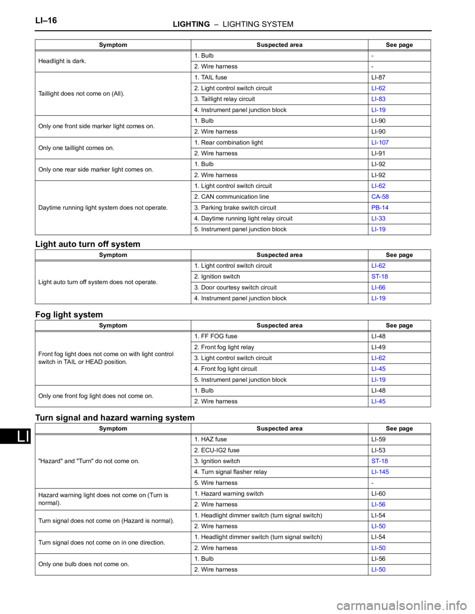
Light auto turn off system
Fog light system
Turn signal and hazard warning system
Headlight is dark.1. Bulb -
2. Wire harness -
Taillight does not come on (All).1. TAIL fuse LI-87
2. Light control switch circuitLI-62
3. Taillight relay circuitLI-83
4. Instrument panel junction blockLI-19
Only one front side marker light comes on.1. Bulb LI-90
2. Wire harness LI-90
Only one taillight comes on.1. Rear combination lightLI-107
2. Wire harness LI-91
Only one rear side marker light comes on.1. Bulb LI-92
2. Wire harness LI-92
Daytime running light system does not operate.1. Light control switch circuitLI-62
2. CAN communication lineCA-58
3. Parking brake switch circuitPB-14
4. Daytime running light relay circuitLI-33
5. Instrument panel junction blockLI-19
Symptom Suspected area See page
Light auto turn off system does not operate.1. Light control switch circuitLI-62
2. Ignition switchST-18
3. Door courtesy switch circuitLI-66
4. Instrument panel junction blockLI-19
Symptom Suspected area See page
Front fog light does not come on with light control
switch in TAIL or HEAD position.1. FF FOG fuse LI-48
2. Front fog light relay LI-49
3. Light control switch circuitLI-62
4. Front fog light circuitLI-45
5. Instrument panel junction blockLI-19
Only one front fog light does not come on.1. Bulb LI-48
2. Wire harnessLI-45
Symptom Suspected area See page
"Hazard" and "Turn" do not come on.1. HAZ fuse LI-59
2. ECU-IG2 fuse LI-53
3. Ignition switchST-18
4. Turn signal flasher relayLI-145
5. Wire harness -
Hazard warning light does not come on (Turn is
normal).1. Hazard warning switch LI-60
2. Wire harnessLI-56
Turn signal does not come on (Hazard is normal).1. Headlight dimmer switch (turn signal switch) LI-54
2. Wire harnessLI-50
Turn signal does not come on in one direction.1. Headlight dimmer switch (turn signal switch) LI-54
2. Wire harnessLI-50
Only one bulb does not come on.1. Bulb LI-56
2. Wire harnessLI-50 Symptom Suspected area See page
Page 1848 of 2000
LIGHTING – LIGHTING SYSTEMLI–17
LI
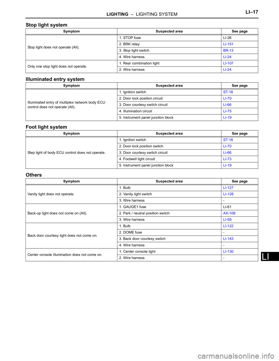
Stop light system
Illuminated entry system
Foot light system
Others
Symptom Suspected area See page
Stop light does not operate (All).1. STOP fuse LI-26
2. BRK relayLI-151
3. Stop light switchBR-13
4. Wire harnessLI-24
Only one stop light does not operate.1. Rear combination lightLI-107
2. Wire harnessLI-24
Symptom Suspected area See page
Illuminated entry of multiplex network body ECU
control does not operate (All).1. Ignition switchST-18
2. Door lock position circuitLI-70
3. Door courtesy switch circuitLI-66
4. Illumination circuitLI-75
5. Instrument panel junction blockLI-19
Symptom Suspected area See page
Step light of body ECU control does not operate.1. Ignition switchST-18
2. Door lock position switchLI-70
3. Door courtesy switch circuitLI-66
4. Footwell light circuitLI-73
5. Instrument panel junction blockLI-19
Symptom Suspected area See page
Vanity light does not operate.1. BulbLI-127
2. Vanity light switchLI-128
3. Wire harness -
Back-up light does not come on (All).1. GAUGE1 fuse LI-61
2. Park / neutral position switchAX-108
3. Wire harnessLI-59
Back door courtesy light does not come on.1. BulbLI-122
2. DOME fuse -
3. Back door courtesy switchLI-143
4. Wire harness -
Center console illumination does not come on.1. Center console lightLI-130
2. Wire harness -