TOYOTA SIENNA 2007 Service Repair Manual
Manufacturer: TOYOTA, Model Year: 2007, Model line: SIENNA, Model: TOYOTA SIENNA 2007Pages: 3000, PDF Size: 52.26 MB
Page 1891 of 3000
AX–208U151F AUTOMATIC TRANSAXLE – AUTOMATIC TRANSAXLE UNIT
AX
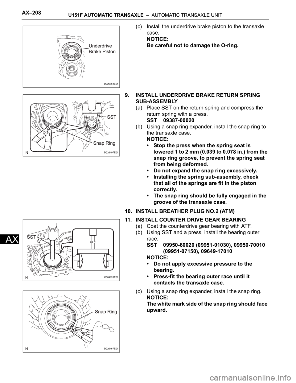
(c) Install the underdrive brake piston to the transaxle
case.
NOTICE:
Be careful not to damage the O-ring.
9. INSTALL UNDERDRIVE BRAKE RETURN SPRING
SUB-ASSEMBLY
(a) Place SST on the return spring and compress the
return spring with a press.
SST 09387-00020
(b) Using a snap ring expander, install the snap ring to
the transaxle case.
NOTICE:
• Stop the press when the spring seat is
lowered 1 to 2 mm (0.039 to 0.078 in.) from the
snap ring groove, to prevent the spring seat
from being deformed.
• Do not expand the snap ring excessively.
• Installing the spring sub-assembly, check
that all of the springs are fit in the piston
correctly.
• The snap ring should be fully engaged in the
groove of the transaxle case.
10. INSTALL BREATHER PLUG NO.2 (ATM)
11. INSTALL COUNTER DRIVE GEAR BEARING
(a) Coat the counterdrive gear bearing with ATF.
(b) Using SST and a press, install the bearing outer
race.
SST 09950-60020 (09951-01030), 09950-70010
(09951-07150), 09649-17010
NOTICE:
• Do not apply excessive pressure to the
bearing.
• Press-fit the bearing outer race until it
contacts the transaxle case.
(c) Using a snap ring expander, install the snap ring.
NOTICE:
The white mark side of the snap ring should face
upward.
D026764E01
D026407E01
C089126E01
D026467E01
Page 1892 of 3000
U151F AUTOMATIC TRANSAXLE – AUTOMATIC TRANSAXLE UNITAX–209
AX
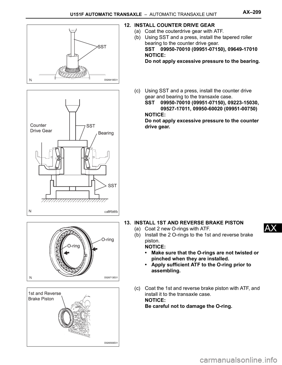
12. INSTALL COUNTER DRIVE GEAR
(a) Coat the couterdrive gear with ATF.
(b) Using SST and a press, install the tapered roller
bearing to the counter drive gear.
SST 09950-70010 (09951-07150), 09649-17010
NOTICE:
Do not apply excessive pressure to the bearing.
(c) Using SST and a press, install the counter drive
gear and bearing to the transaxle case.
SST 09950-70010 (09951-07150), 09223-15030,
09527-17011, 09950-60020 (09951-00750)
NOTICE:
Do not apply excessive pressure to the counter
drive gear.
13. INSTALL 1ST AND REVERSE BRAKE PISTON
(a) Coat 2 new O-rings with ATF.
(b) Install the 2 O-rings to the 1st and reverse brake
piston.
NOTICE:
• Make sure that the O-rings are not twisted or
pinched when they are installed.
• Apply sufficient ATF to the O-ring prior to
assembling.
(c) Coat the 1st and reverse brake piston with ATF, and
install it to the transaxle case.
NOTICE:
Be careful not to damage the O-ring.
D026410E01
C089122E02
D026713E01
D026593E01
Page 1893 of 3000
AX–210U151F AUTOMATIC TRANSAXLE – AUTOMATIC TRANSAXLE UNIT
AX
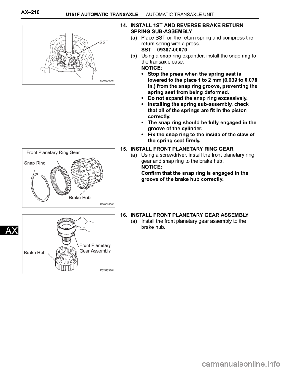
14. INSTALL 1ST AND REVERSE BRAKE RETURN
SPRING SUB-ASSEMBLY
(a) Place SST on the return spring and compress the
return spring with a press.
SST 09387-00070
(b) Using a snap ring expander, install the snap ring to
the transaxle case.
NOTICE:
• Stop the press when the spring seat is
lowered to the place 1 to 2 mm (0.039 to 0.078
in.) from the snap ring groove, preventing the
spring seat from being deformed.
• Do not expand the snap ring excessively.
• Installing the spring sub-assembly, check
that all of the springs are fit in the piston
correctly.
• The snap ring should be fully engaged in the
groove of the cylinder.
• Fix the snap ring to the inside of the claw of
the spring seat firmly.
15. INSTALL FRONT PLANETARY RING GEAR
(a) Using a screwdriver, install the front planetary ring
gear and snap ring to the brake hub.
NOTICE:
Confirm that the snap ring is engaged in the
groove of the brake hub correctly.
16. INSTALL FRONT PLANETARY GEAR ASSEMBLY
(a) Install the front planetary gear assembly to the
brake hub.
D003600E01
D003615E02
D026763E01
Page 1894 of 3000
U151F AUTOMATIC TRANSAXLE – AUTOMATIC TRANSAXLE UNITAX–211
AX
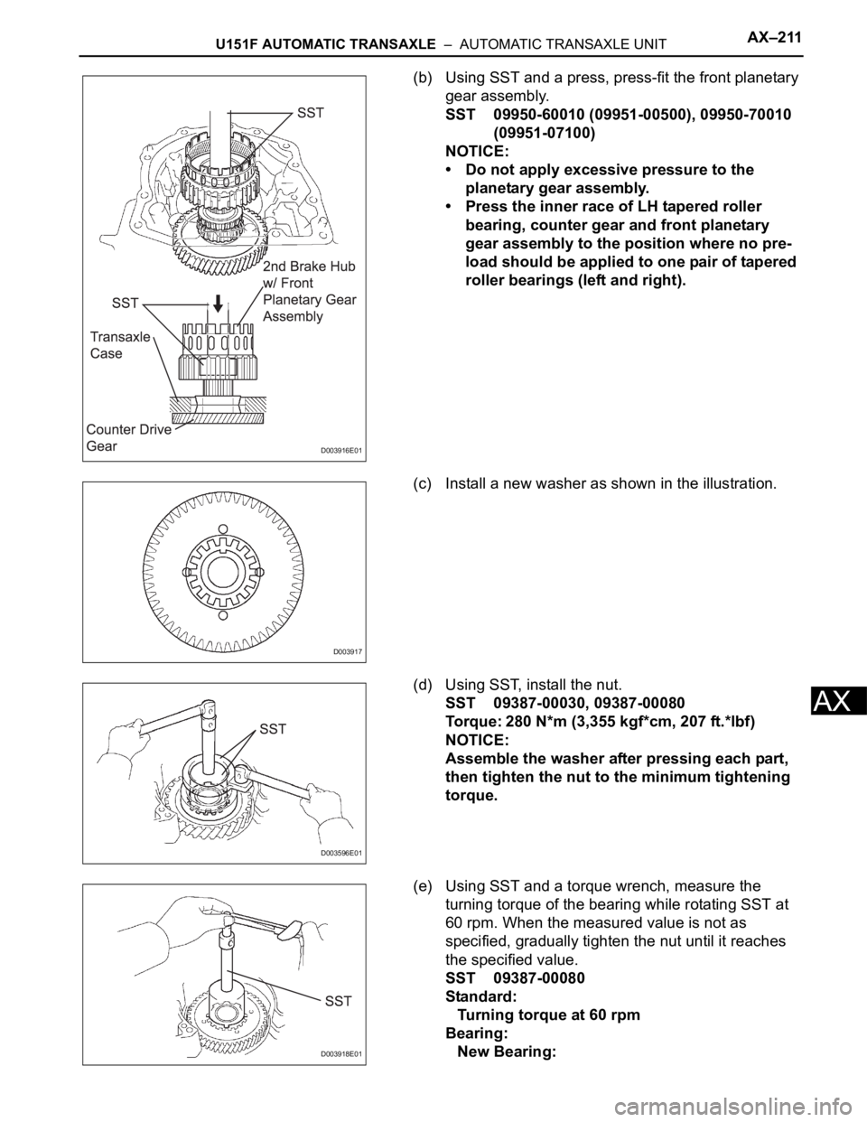
(b) Using SST and a press, press-fit the front planetary
gear assembly.
SST 09950-60010 (09951-00500), 09950-70010
(09951-07100)
NOTICE:
• Do not apply excessive pressure to the
planetary gear assembly.
• Press the inner race of LH tapered roller
bearing, counter gear and front planetary
gear assembly to the position where no pre-
load should be applied to one pair of tapered
roller bearings (left and right).
(c) Install a new washer as shown in the illustration.
(d) Using SST, install the nut.
SST 09387-00030, 09387-00080
Torque: 280 N*m (3,355 kgf*cm, 207 ft.*lbf)
NOTICE:
Assemble the washer after pressing each part,
then tighten the nut to the minimum tightening
torque.
(e) Using SST and a torque wrench, measure the
turning torque of the bearing while rotating SST at
60 rpm. When the measured value is not as
specified, gradually tighten the nut until it reaches
the specified value.
SST 09387-00080
Standard:
Turning torque at 60 rpm
Bearing:
New Bearing:
D003916E01
D003917
D003596E01
D003918E01
Page 1895 of 3000
AX–212U151F AUTOMATIC TRANSAXLE – AUTOMATIC TRANSAXLE UNIT
AX
0.51 to 1.02 N*m (5.1 to 10.0 kgf*cm, 4.4 to 8.7
in.*lbf)
Used Bearing:
0.26 to 0.51 N*m (2.7 to 5.2 kgf*cm, 2.3 to 4.5
in.*lbf)
HINT:
Use a torque wrench with a fulcrum length of 160
mm (6.3 in.).
(f) Tighten the nut gradually until the specified turning
torque of tapered roller bearing is measured.
Torque: 350 N*m (3,569 kgf*cm, 258 ft.*lbf)
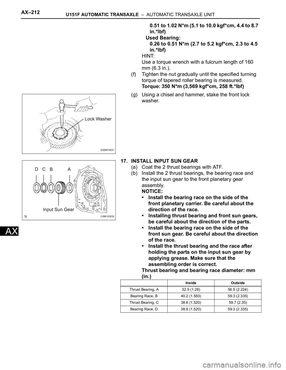
(g) Using a chisel and hammer, stake the front lock
washer.
17. INSTALL INPUT SUN GEAR
(a) Coat the 2 thrust bearings with ATF.
(b) Install the 2 thrust bearings, the bearing race and
the input sun gear to the front planetary gear
assembly.
NOTICE:
• Install the bearing race on the side of the
front planetary carrier. Be careful about the
direction of the race.
• Installing thrust bearing and front sun gears,
be careful about the direction of the parts.
• Install the bearing race on the side of the
front sun gear. Be careful about the direction
of the race.
• Install the thrust bearing and the race after
holding the parts on the input sun gear by
applying grease. Make sure that the
assembling order is correct.
Thrust bearing and bearing race diameter: mm
(in.)
D008074E01
C089123E02
Inside Outside
Thrust Bearing, A 32.5 (1.28) 56.5 (2.224)
Bearing Race, B 40.2 (1.583) 59.3 (2.335)
Thrust Bearing, C 38.6 (1.520) 59.7 (2.35)
Bearing Race, D 38.6 (1.520) 59.3 (2.335)
Page 1896 of 3000
U151F AUTOMATIC TRANSAXLE – AUTOMATIC TRANSAXLE UNITAX–213
AX
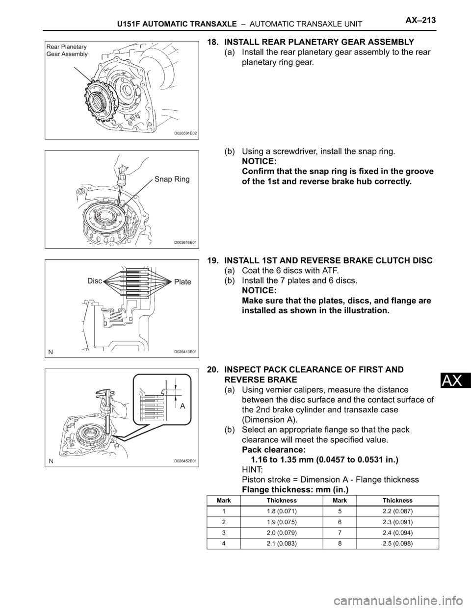
18. INSTALL REAR PLANETARY GEAR ASSEMBLY
(a) Install the rear planetary gear assembly to the rear
planetary ring gear.
(b) Using a screwdriver, install the snap ring.
NOTICE:
Confirm that the snap ring is fixed in the groove
of the 1st and reverse brake hub correctly.
19. INSTALL 1ST AND REVERSE BRAKE CLUTCH DISC
(a) Coat the 6 discs with ATF.
(b) Install the 7 plates and 6 discs.
NOTICE:
Make sure that the plates, discs, and flange are
installed as shown in the illustration.
20. INSPECT PACK CLEARANCE OF FIRST AND
REVERSE BRAKE
(a) Using vernier calipers, measure the distance
between the disc surface and the contact surface of
the 2nd brake cylinder and transaxle case
(Dimension A).
(b) Select an appropriate flange so that the pack
clearance will meet the specified value.
Pack clearance:
1.16 to 1.35 mm (0.0457 to 0.0531 in.)
HINT:
Piston stroke = Dimension A - Flange thickness
Flange thickness: mm (in.)
D026591E02
D003616E01
D026413E01
D026452E01
Mark Thickness Mark Thickness
1 1.8 (0.071) 5 2.2 (0.087)
2 1.9 (0.075) 6 2.3 (0.091)
3 2.0 (0.079) 7 2.4 (0.094)
4 2.1 (0.083) 8 2.5 (0.098)
Page 1897 of 3000
AX–214U151F AUTOMATIC TRANSAXLE – AUTOMATIC TRANSAXLE UNIT
AX
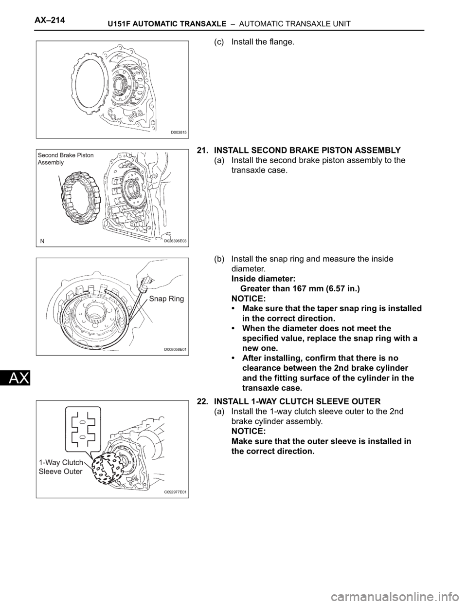
(c) Install the flange.
21. INSTALL SECOND BRAKE PISTON ASSEMBLY
(a) Install the second brake piston assembly to the
transaxle case.
(b) Install the snap ring and measure the inside
diameter.
Inside diameter:
Greater than 167 mm (6.57 in.)
NOTICE:
• Make sure that the taper snap ring is installed
in the correct direction.
• When the diameter does not meet the
specified value, replace the snap ring with a
new one.
• After installing, confirm that there is no
clearance between the 2nd brake cylinder
and the fitting surface of the cylinder in the
transaxle case.
22. INSTALL 1-WAY CLUTCH SLEEVE OUTER
(a) Install the 1-way clutch sleeve outer to the 2nd
brake cylinder assembly.
NOTICE:
Make sure that the outer sleeve is installed in
the correct direction.
D003815
D026396E03
D008058E01
C092977E01
Page 1898 of 3000
U151F AUTOMATIC TRANSAXLE – AUTOMATIC TRANSAXLE UNITAX–215
AX
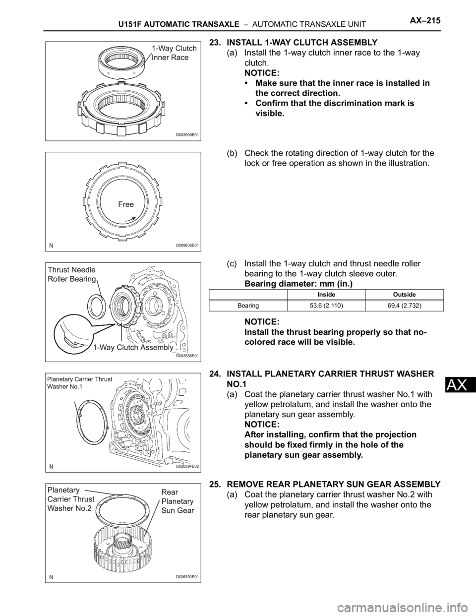
23. INSTALL 1-WAY CLUTCH ASSEMBLY
(a) Install the 1-way clutch inner race to the 1-way
clutch.
NOTICE:
• Make sure that the inner race is installed in
the correct direction.
• Confirm that the discrimination mark is
visible.
(b) Check the rotating direction of 1-way clutch for the
lock or free operation as shown in the illustration.
(c) Install the 1-way clutch and thrust needle roller
bearing to the 1-way clutch sleeve outer.
Bearing diameter: mm (in.)
NOTICE:
Install the thrust bearing properly so that no-
colored race will be visible.
24. INSTALL PLANETARY CARRIER THRUST WASHER
NO.1
(a) Coat the planetary carrier thrust washer No.1 with
yellow petrolatum, and install the washer onto the
planetary sun gear assembly.
NOTICE:
After installing, confirm that the projection
should be fixed firmly in the hole of the
planetary sun gear assembly.
25. REMOVE REAR PLANETARY SUN GEAR ASSEMBLY
(a) Coat the planetary carrier thrust washer No.2 with
yellow petrolatum, and install the washer onto the
rear planetary sun gear.
D003909E01
D009638E01
D003588E01
Inside Outside
Bearing 53.6 (2.110) 69.4 (2.732)
D026394E02
D026393E01
Page 1899 of 3000
AX–216U151F AUTOMATIC TRANSAXLE – AUTOMATIC TRANSAXLE UNIT
AX
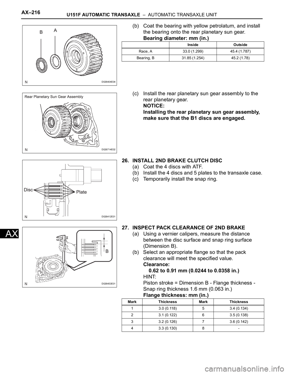
(b) Coat the bearing with yellow petrolatum, and install
the bearing onto the rear planetary sun gear.
Bearing diameter: mm (in.)
(c) Install the rear planetary sun gear assembly to the
rear planetary gear.
NOTICE:
Installing the rear planetary sun gear assembly,
make sure that the B1 discs are engaged.
26. INSTALL 2ND BRAKE CLUTCH DISC
(a) Coat the 4 discs with ATF.
(b) Install the 4 discs and 5 plates to the transaxle case.
(c) Temporarily install the snap ring.
27. INSPECT PACK CLEARANCE OF 2ND BRAKE
(a) Using a vernier calipers, measure the distance
between the disc surface and snap ring surface
(Dimension B).
(b) Select an appropriate flange so that the pack
clearance will meet the specified value.
Clearance:
0.62 to 0.91 mm (0.0244 to 0.0358 in.)
HINT:
Piston stroke = Dimension B - Flange thickness -
Snap ring thickness 1.6 mm (0.063 in.)
Flange thickness: mm (in.)
D026404E04
Inside Outside
Race, A 33.0 (1.299) 45.4 (1.787)
Bearing, B 31.85 (1.254) 45.2 (1.78)
D026714E02
D026412E01
D026453E01
Mark Thickness Mark Thickness
1 3.0 (0.118) 5 3.4 (0.134)
2 3.1 (0.122) 6 3.5 (0.138)
3 3.2 (0.126) 7 3.6 (0.142)
4 3.3 (0.130) 8 -
Page 1900 of 3000
U151F AUTOMATIC TRANSAXLE – AUTOMATIC TRANSAXLE UNITAX–217
AX
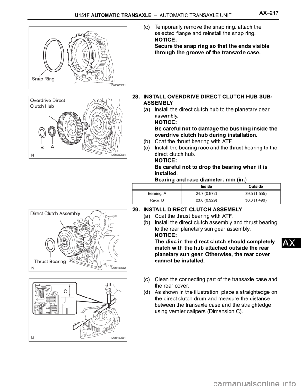
(c) Temporarily remove the snap ring, attach the
selected flange and reinstall the snap ring.
NOTICE:
Secure the snap ring so that the ends visible
through the groove of the transaxle case.
28. INSTALL OVERDRIVE DIRECT CLUTCH HUB SUB-
ASSEMBLY
(a) Install the direct clutch hub to the planetary gear
assembly.
NOTICE:
Be careful not to damage the bushing inside the
overdrive clutch hub during installation.
(b) Coat the thrust bearing with ATF.
(c) Install the bearing race and the thrust bearing to the
direct clutch hub.
NOTICE:
Be careful not to drop the bearing when it is
installed.
Bearing and race diameter: mm (in.)
29. INSTALL DIRECT CLUTCH ASSEMBLY
(a) Coat the thrust bearing with ATF.
(b) Install the direct clutch assembly and thrust bearing
to the rear planetary sun gear assembly.
NOTICE:
The disc in the direct clutch should completely
match with the hub attached outside the rear
planetary sun gear. Otherwise, the rear cover
cannot be installed.
(c) Clean the connecting part of the transaxle case and
the rear cover.
(d) As shown in the illustration, place a straightedge on
the direct clutch drum and measure the distance
between the transaxle case and the straightedge
using vernier calipers (Dimension C).
D003623E01
D026392E04
Inside Outside
Bearing, A 24.7 (0.972) 39.5 (1.555)
Race, B 23.6 (0.929) 38.0 (1.496)
D026403E02
D026469E01