TOYOTA SIENNA 2007 Service Repair Manual
SIENNA 2007
TOYOTA
TOYOTA
https://www.carmanualsonline.info/img/14/57466/w960_57466-0.png
TOYOTA SIENNA 2007 Service Repair Manual
Trending: Trans, radio, fuse box, height, ignition, coolant, sensor
Page 201 of 3000
AIR CONDITIONING – AIR CONDITIONING SYSTEM (for Automatic Air Conditioning Sys-
tem)AC–3
AC
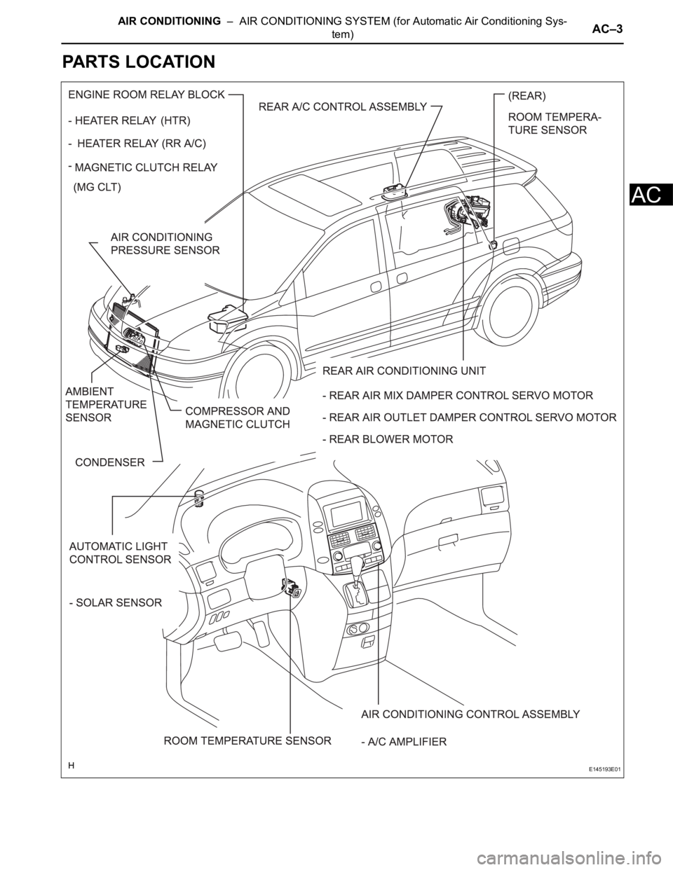
PARTS LOCATION
E145193E01
Page 202 of 3000
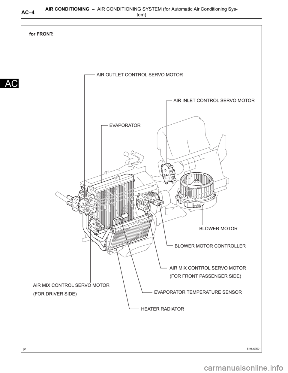
AC–4AIR CONDITIONING – AIR CONDITIONING SYSTEM (for Automatic Air Conditioning Sys-
tem)
AC
E145207E01
Page 203 of 3000
AIR CONDITIONING – AIR CONDITIONING SYSTEM (for Automatic Air Conditioning Sys-
tem)AC–5
AC
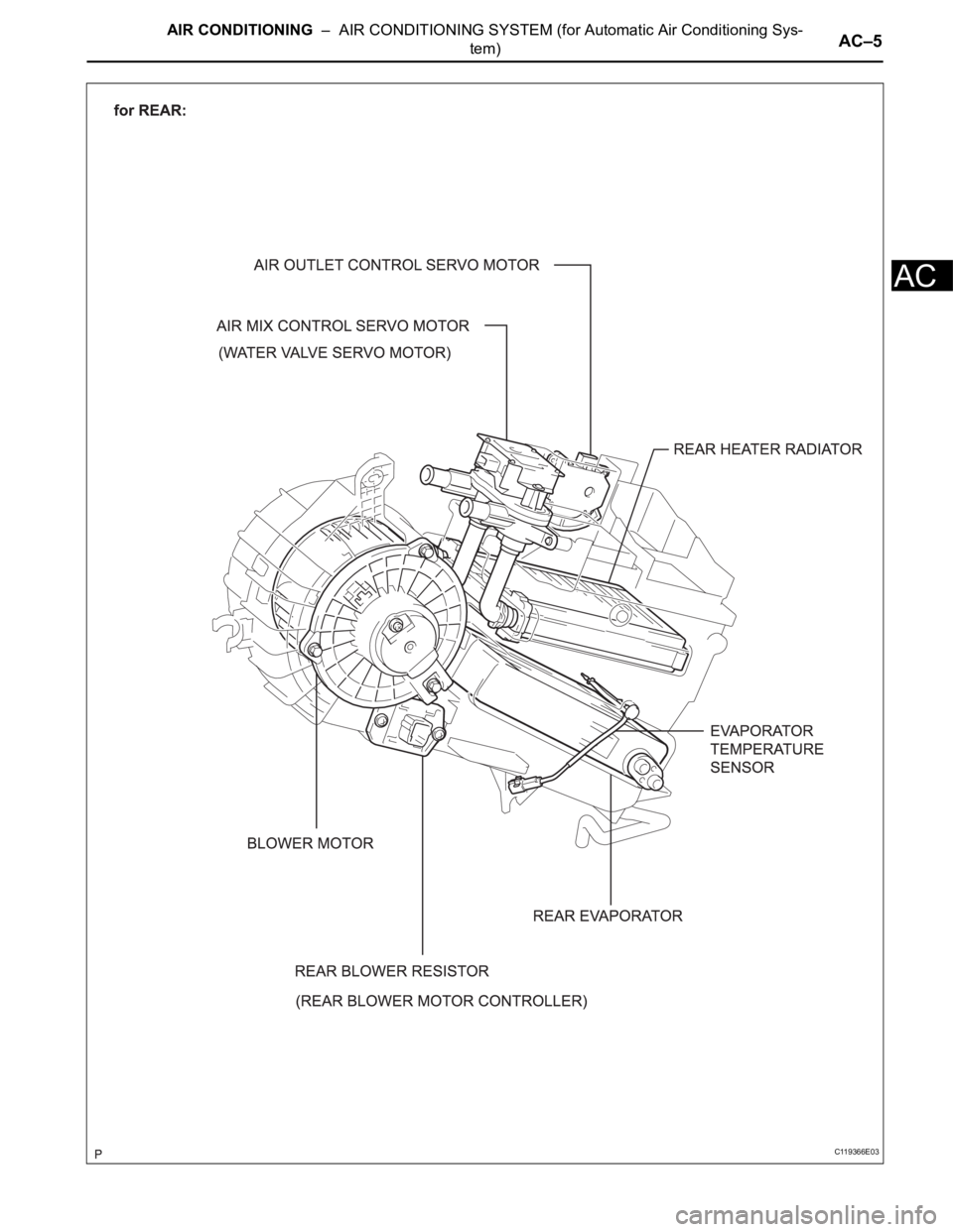
C119366E03
Page 204 of 3000
AIR CONDITIONING – COMPRESSOR AND MAGNETIC CLUTCHAC–227
AC
REMOVAL
1. RECOVER REFRIGERANT FROM REFRIGERATION
SYSTEM (See page AC-172)
2. REMOVE FRONT WHEEL RH
3. REMOVE FRONT FENDER APRON SEAL RH (See
page EM-26)
4. REMOVE V-RIBBED BELT (See page EM-6)
5. REMOVE RADIATOR AND FAN ASSEMBLY
(See page CO-28)
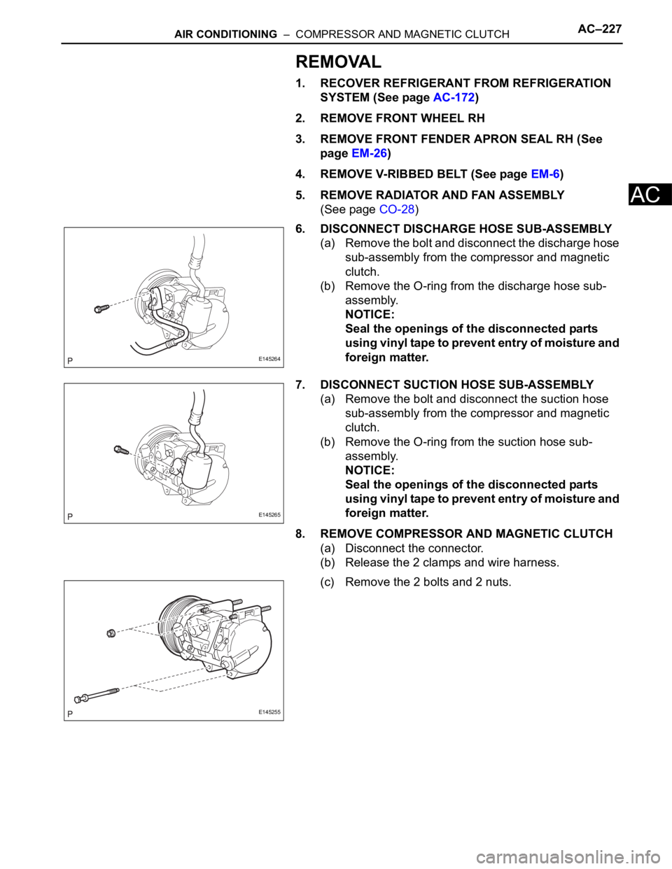
6. DISCONNECT DISCHARGE HOSE SUB-ASSEMBLY
(a) Remove the bolt and disconnect the discharge hose
sub-assembly from the compressor and magnetic
clutch.
(b) Remove the O-ring from the discharge hose sub-
assembly.
NOTICE:
Seal the openings of the disconnected parts
using vinyl tape to prevent entry of moisture and
foreign matter.
7. DISCONNECT SUCTION HOSE SUB-ASSEMBLY
(a) Remove the bolt and disconnect the suction hose
sub-assembly from the compressor and magnetic
clutch.
(b) Remove the O-ring from the suction hose sub-
assembly.
NOTICE:
Seal the openings of the disconnected parts
using vinyl tape to prevent entry of moisture and
foreign matter.
8. REMOVE COMPRESSOR AND MAGNETIC CLUTCH
(a) Disconnect the connector.
(b) Release the 2 clamps and wire harness.
(c) Remove the 2 bolts and 2 nuts.
E145264
E145265
E145255
Page 205 of 3000
AC–228AIR CONDITIONING – COMPRESSOR AND MAGNETIC CLUTCH
AC
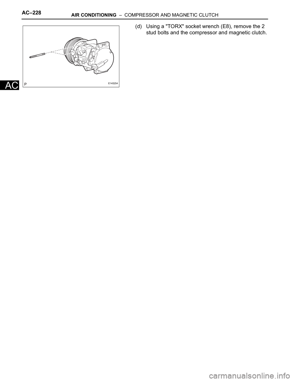
(d) Using a "TORX" socket wrench (E8), remove the 2
stud bolts and the compressor and magnetic clutch.
E145254
Page 206 of 3000
AC–236AIR CONDITIONING – CONDENSER
AC
ON-VEHICLE INSPECTION
1. INSPECT COOLER CONDENSER CORE
(a) If the fin of the cooler condenser core is dirty, clean
it with water and dry it with compressed air.
NOTICE:
Do not damage the fin of the cooler condenser
core.
(b) If the fin of the cooler condenser core is bent, make
it straight using a screwdriver or pliers.
2. INSPECT CONDENSER FOR LEAKAGE OF
REFRIGERANT
(a) Using a halogen leak detector, check the pipe joints
for gas leakage.
(b) If gas leakage is detected in a joint, check the
torque of the joint.
Page 207 of 3000
AIR CONDITIONING – CONDENSERAC–237
AC
REMOVAL
1. RECOVER REFRIGERANT FROM REFRIGERATION
SYSTEM (See page AC-172)
2. REMOVE NO. 2 AIR CLEANER INLET (See page EM-
28)
3. REMOVE FRONT BUMPER ASSEMBLY (See page
ET-3)
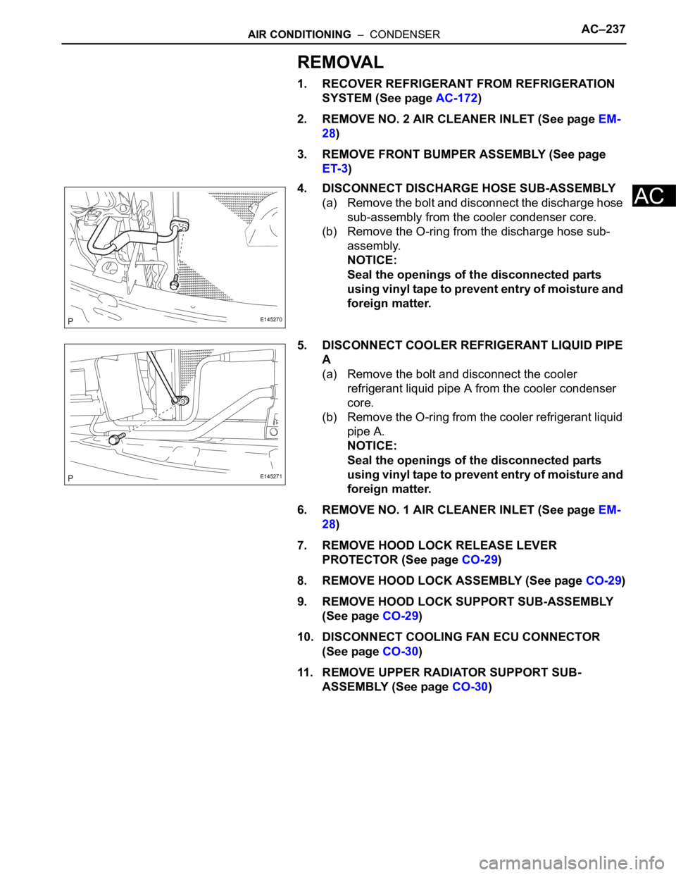
4. DISCONNECT DISCHARGE HOSE SUB-ASSEMBLY
(a) Remove the bolt and disconnect the discharge hose
sub-assembly from the cooler condenser core.
(b) Remove the O-ring from the discharge hose sub-
assembly.
NOTICE:
Seal the openings of the disconnected parts
using vinyl tape to prevent entry of moisture and
foreign matter.
5. DISCONNECT COOLER REFRIGERANT LIQUID PIPE
A
(a) Remove the bolt and disconnect the cooler
refrigerant liquid pipe A from the cooler condenser
core.
(b) Remove the O-ring from the cooler refrigerant liquid
pipe A.
NOTICE:
Seal the openings of the disconnected parts
using vinyl tape to prevent entry of moisture and
foreign matter.
6. REMOVE NO. 1 AIR CLEANER INLET (See page EM-
28)
7. REMOVE HOOD LOCK RELEASE LEVER
PROTECTOR (See page CO-29)
8. REMOVE HOOD LOCK ASSEMBLY (See page CO-29)
9. REMOVE HOOD LOCK SUPPORT SUB-ASSEMBLY
(See page CO-29)
10. DISCONNECT COOLING FAN ECU CONNECTOR
(See page CO-30)
11. REMOVE UPPER RADIATOR SUPPORT SUB-
ASSEMBLY (See page CO-30)
E145270
E145271
Page 208 of 3000
AC–238AIR CONDITIONING – CONDENSER
AC
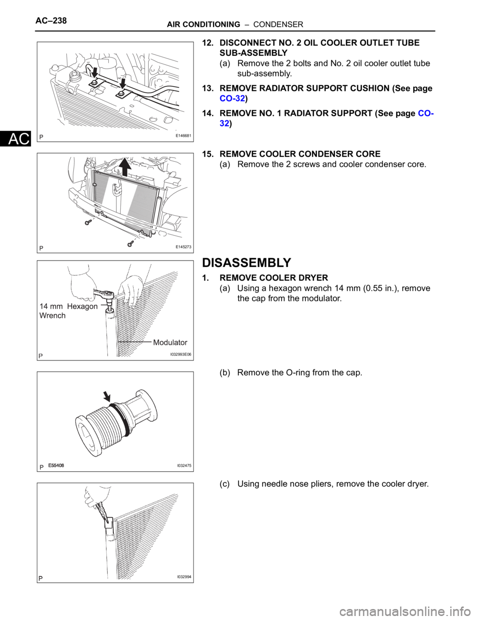
12. DISCONNECT NO. 2 OIL COOLER OUTLET TUBE
SUB-ASSEMBLY
(a) Remove the 2 bolts and No. 2 oil cooler outlet tube
sub-assembly.
13. REMOVE RADIATOR SUPPORT CUSHION (See page
CO-32)
14. REMOVE NO. 1 RADIATOR SUPPORT (See page CO-
32)
15. REMOVE COOLER CONDENSER CORE
(a) Remove the 2 screws and cooler condenser core.
DISASSEMBLY
1. REMOVE COOLER DRYER
(a) Using a hexagon wrench 14 mm (0.55 in.), remove
the cap from the modulator.
(b) Remove the O-ring from the cap.
(c) Using needle nose pliers, remove the cooler dryer.
E146681
E145273
I032993E06
I032475
I032994
Page 209 of 3000
AIR CONDITIONING – CONDENSERAC–239
AC
REASSEMBLY
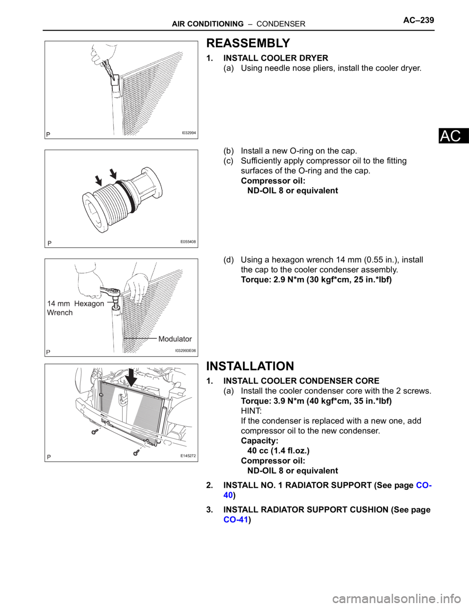
1. INSTALL COOLER DRYER
(a) Using needle nose pliers, install the cooler dryer.
(b) Install a new O-ring on the cap.
(c) Sufficiently apply compressor oil to the fitting
surfaces of the O-ring and the cap.
Compressor oil:
ND-OIL 8 or equivalent
(d) Using a hexagon wrench 14 mm (0.55 in.), install
the cap to the cooler condenser assembly.
Torque: 2.9 N*m (30 kgf*cm, 25 in.*lbf)
INSTALLATION
1. INSTALL COOLER CONDENSER CORE
(a) Install the cooler condenser core with the 2 screws.
Torque: 3.9 N*m (40 kgf*cm, 35 in.*lbf)
HINT:
If the condenser is replaced with a new one, add
compressor oil to the new condenser.
Capacity:
40 cc (1.4 fl.oz.)
Compressor oil:
ND-OIL 8 or equivalent
2. INSTALL NO. 1 RADIATOR SUPPORT (See page CO-
40)
3. INSTALL RADIATOR SUPPORT CUSHION (See page
CO-41)
I032994
E055408
I032993E06
E145272
Page 210 of 3000
AC–240AIR CONDITIONING – CONDENSER
AC
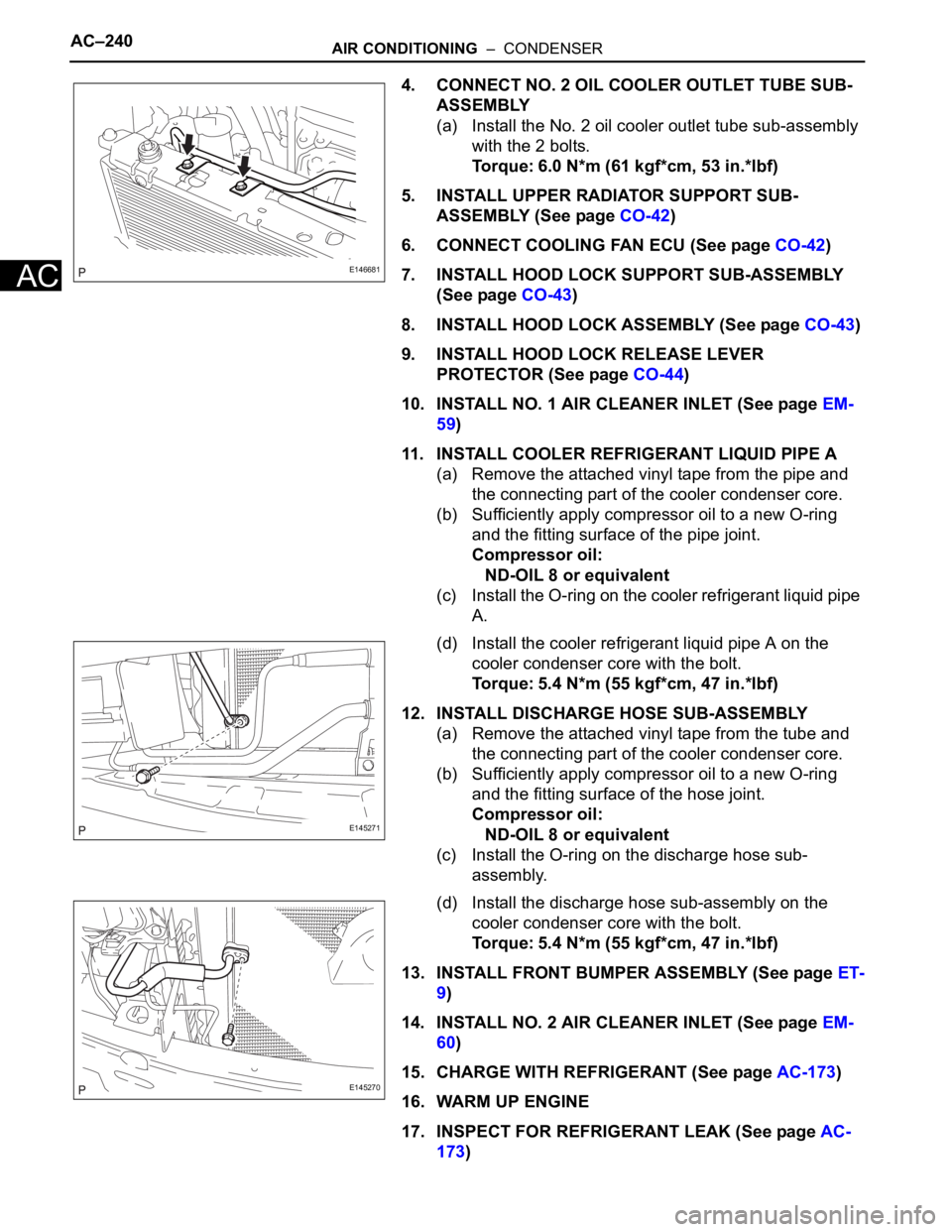
4. CONNECT NO. 2 OIL COOLER OUTLET TUBE SUB-
ASSEMBLY
(a) Install the No. 2 oil cooler outlet tube sub-assembly
with the 2 bolts.
Torque: 6.0 N*m (61 kgf*cm, 53 in.*lbf)
5. INSTALL UPPER RADIATOR SUPPORT SUB-
ASSEMBLY (See page CO-42)
6. CONNECT COOLING FAN ECU (See page CO-42)
7. INSTALL HOOD LOCK SUPPORT SUB-ASSEMBLY
(See page CO-43)
8. INSTALL HOOD LOCK ASSEMBLY (See page CO-43)
9. INSTALL HOOD LOCK RELEASE LEVER
PROTECTOR (See page CO-44)
10. INSTALL NO. 1 AIR CLEANER INLET (See page EM-
59)
11. INSTALL COOLER REFRIGERANT LIQUID PIPE A
(a) Remove the attached vinyl tape from the pipe and
the connecting part of the cooler condenser core.
(b) Sufficiently apply compressor oil to a new O-ring
and the fitting surface of the pipe joint.
Compressor oil:
ND-OIL 8 or equivalent
(c) Install the O-ring on the cooler refrigerant liquid pipe
A.
(d) Install the cooler refrigerant liquid pipe A on the
cooler condenser core with the bolt.
Torque: 5.4 N*m (55 kgf*cm, 47 in.*lbf)
12. INSTALL DISCHARGE HOSE SUB-ASSEMBLY
(a) Remove the attached vinyl tape from the tube and
the connecting part of the cooler condenser core.
(b) Sufficiently apply compressor oil to a new O-ring
and the fitting surface of the hose joint.
Compressor oil:
ND-OIL 8 or equivalent
(c) Install the O-ring on the discharge hose sub-
assembly.
(d) Install the discharge hose sub-assembly on the
cooler condenser core with the bolt.
Torque: 5.4 N*m (55 kgf*cm, 47 in.*lbf)
13. INSTALL FRONT BUMPER ASSEMBLY (See page ET-
9)
14. INSTALL NO. 2 AIR CLEANER INLET (See page EM-
60)
15. CHARGE WITH REFRIGERANT (See page AC-173)
16. WARM UP ENGINE
17. INSPECT FOR REFRIGERANT LEAK (See page AC-
173)
E146681
E145271
E145270
Trending: maintenance reset, run flat, load capacity, immobilizer system, clock, rear hub, warning light
