TOYOTA SIENNA 2007 Service Repair Manual
SIENNA 2007
TOYOTA
TOYOTA
https://www.carmanualsonline.info/img/14/57466/w960_57466-0.png
TOYOTA SIENNA 2007 Service Repair Manual
Trending: rear entertainment, phone, navigation update, width, tire type, ad blue, removal
Page 2131 of 3000
DIFFERENTIAL – REAR DIFFERENTIAL CARRIERDF–33
DF
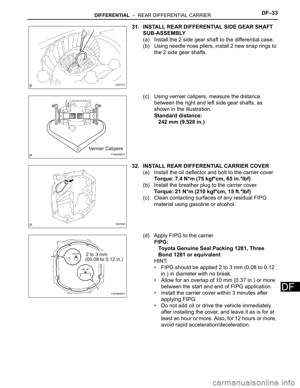
31. INSTALL REAR DIFFERENTIAL SIDE GEAR SHAFT
SUB-ASSEMBLY
(a) Install the 2 side gear shaft to the differential case.
(b) Using needle nose pliers, install 2 new snap rings to
the 2 side gear shafts.
(c) Using vernier calipers, measure the distance
between the right and left side gear shafts, as
shown in the illustration.
Standard distance:
242 mm (9.528 in.)
32. INSTALL REAR DIFFERENTIAL CARRIER COVER
(a) Install the oil deflector and bolt to the carrier cover.
Torque: 7.4 N*m (75 kgf*cm, 65 in.*lbf)
(b) Install the breather plug to the carrier cover.
Torque: 21 N*m (210 kgf*cm, 15 ft.*lbf)
(c) Clean contacting surfaces of any residual FIPG
material using gasoline or alcohol.
(d) Apply FIPG to the carrier.
FIPG:
Toyota Genuine Seal Packing 1281, Three
Bond 1281 or equivalent
HINT:
• FIPG should be applied 2 to 3 mm (0.08 to 0.12
in.) in diameter with no break.
• Allow for an overlap of 10 mm (0.37 in.) or more
between the start and end of FIPG application.
• Install the carrier cover within 3 minutes after
applying FIPG.
• Do not add oil or drive the vehicle immediately
after installing the cover, and leave it as is for at
least an hour or more. Also, for 12 hours or more,
avoid rapid acceleration/deceleration.
C067701
F040466E01
C067695
F003983E01
Page 2132 of 3000
DF–34DIFFERENTIAL – REAR DIFFERENTIAL CARRIER
DF
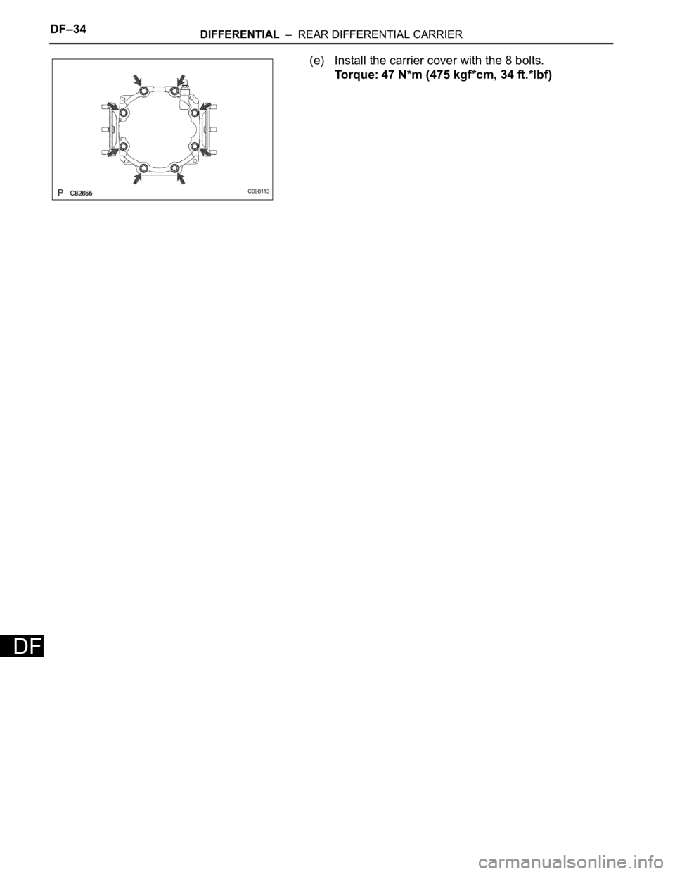
(e) Install the carrier cover with the 8 bolts.
Torque: 47 N*m (475 kgf*cm, 34 ft.*lbf)
C098113
Page 2133 of 3000
DIFFERENTIAL – DIFFERENTIAL OILDF–3
DF
DIFFERENTIAL OIL
ADJUSTMENT
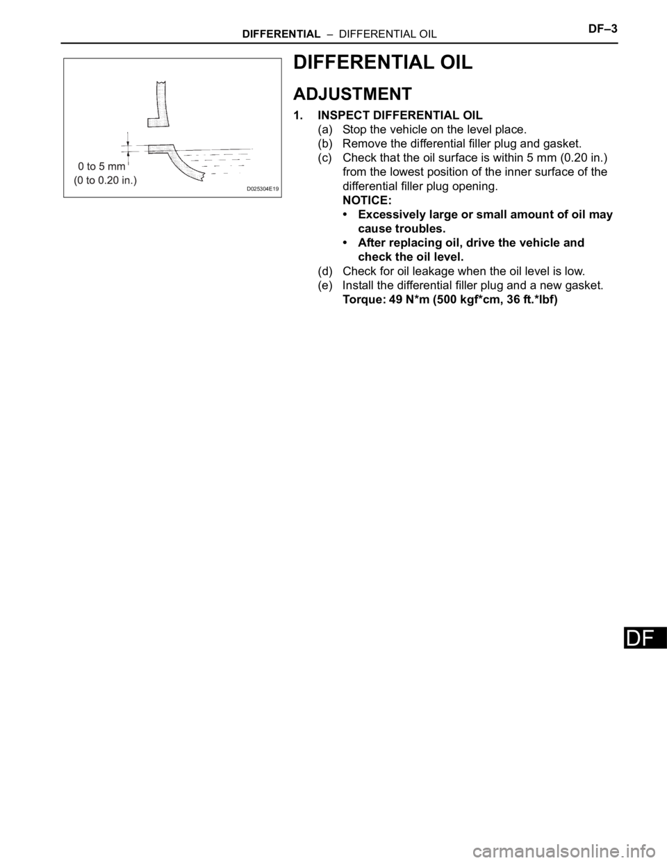
1. INSPECT DIFFERENTIAL OIL
(a) Stop the vehicle on the level place.
(b) Remove the differential filler plug and gasket.
(c) Check that the oil surface is within 5 mm (0.20 in.)
from the lowest position of the inner surface of the
differential filler plug opening.
NOTICE:
• Excessively large or small amount of oil may
cause troubles.
• After replacing oil, drive the vehicle and
check the oil level.
(d) Check for oil leakage when the oil level is low.
(e) Install the differential filler plug and a new gasket.
Torque: 49 N*m (500 kgf*cm, 36 ft.*lbf)
D025304E19
Page 2134 of 3000
DF–8DIFFERENTIAL – REAR DIFFERENTIAL CARRIER ASSEMBLY
DF
DRIVE LINE
DIFFERENTIAL
REAR DIFFERENTIAL CARRIER ASSEMBLY
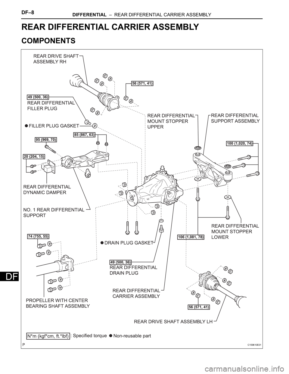
COMPONENTS
C159610E01
Page 2135 of 3000
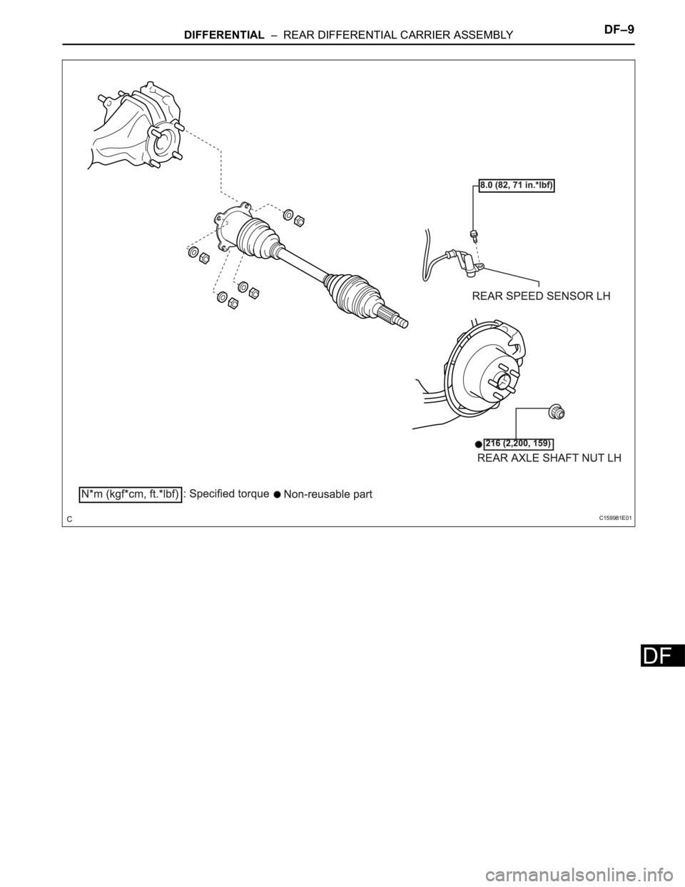
DIFFERENTIAL – REAR DIFFERENTIAL CARRIER ASSEMBLYDF–9
DF
C159981E01
Page 2136 of 3000
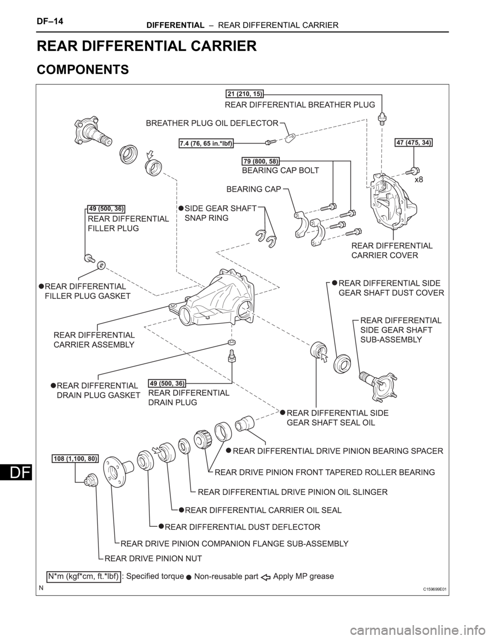
DF–14DIFFERENTIAL – REAR DIFFERENTIAL CARRIER
DF
DRIVE LINE
DIFFERENTIAL
REAR DIFFERENTIAL CARRIER
COMPONENTS
C159699E01
Page 2137 of 3000
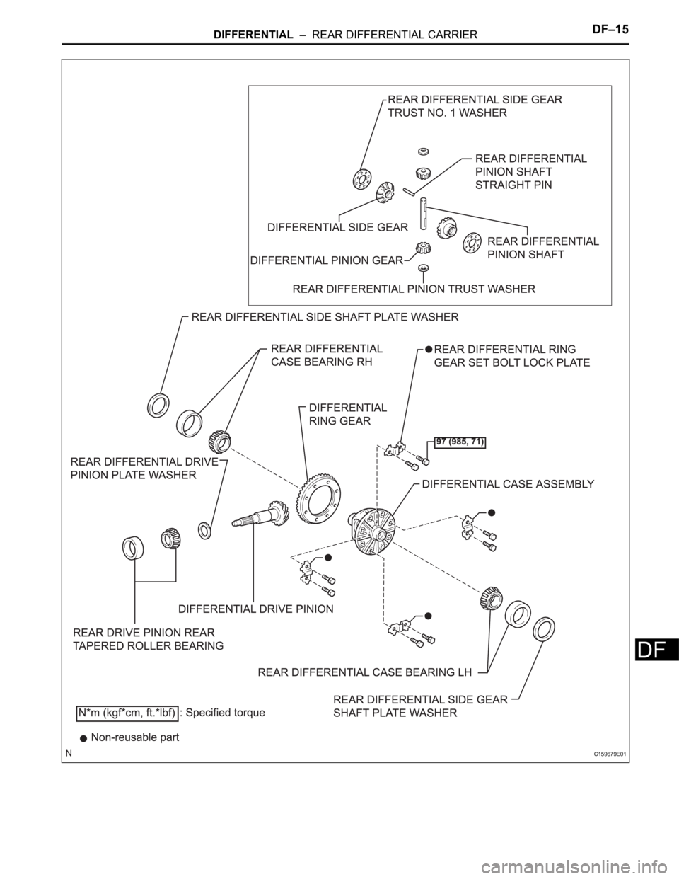
DIFFERENTIAL – REAR DIFFERENTIAL CARRIERDF–15
DF
C159679E01
Page 2138 of 3000
DF–16DIFFERENTIAL – REAR DIFFERENTIAL CARRIER
DF
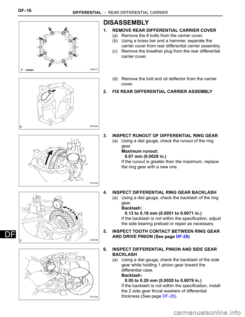
DISASSEMBLY
1. REMOVE REAR DIFFERENTIAL CARRIER COVER
(a) Remove the 8 bolts from the carrier cover.
(b) Using a brass bar and a hammer, separate the
carrier cover from rear differential carrier assembly.
(c) Remove the breather plug from the rear differential
carrier cover.
(d) Remove the bolt and oil deflector from the carrier
cover.
2. FIX REAR DIFFERENTIAL CARRIER ASSEMBLY
3. INSPECT RUNOUT OF DIFFERENTIAL RING GEAR
(a) Using a dial gauge, check the runout of the ring
gear.
Maximum runout:
0.07 mm (0.0028 in.)
If the runout is greater than the maximum, replace
the ring gear with a new one.
4. INSPECT DIFFERENTIAL RING GEAR BACKLASH
(a) Using a dial gauge, check the backlash of the ring
gear.
Backlash:
0.13 to 0.18 mm (0.0051 to 0.0071 in.)
If the backlash is not within the specification, adjust
the side bearing preload or repair as necessary.
5. INSPECT TOOTH CONTACT BETWEEN RING GEAR
AND DRIVE PINION (See page DF-28)
6. INSPECT DIFFERENTIAL PINION AND SIDE GEAR
BACKLASH
(a) Using a dial gauge, check the backlash of the side
gear while holding 1 pinion gear toward the
differential case.
Backlash:
0.05 to 0.20 mm (0.0020 to 0.0079 in.)
If the backlash is not within the specification, install
the 2 side gear thrust washers of differential
thickness (See page DF-26).
C098113
C067695
F001238
C067698
F001240
Page 2139 of 3000
DIFFERENTIAL – REAR DIFFERENTIAL CARRIERDF–17
DF
HINT:
Measure the backlash of the side gear with the side
gear shaft installed.
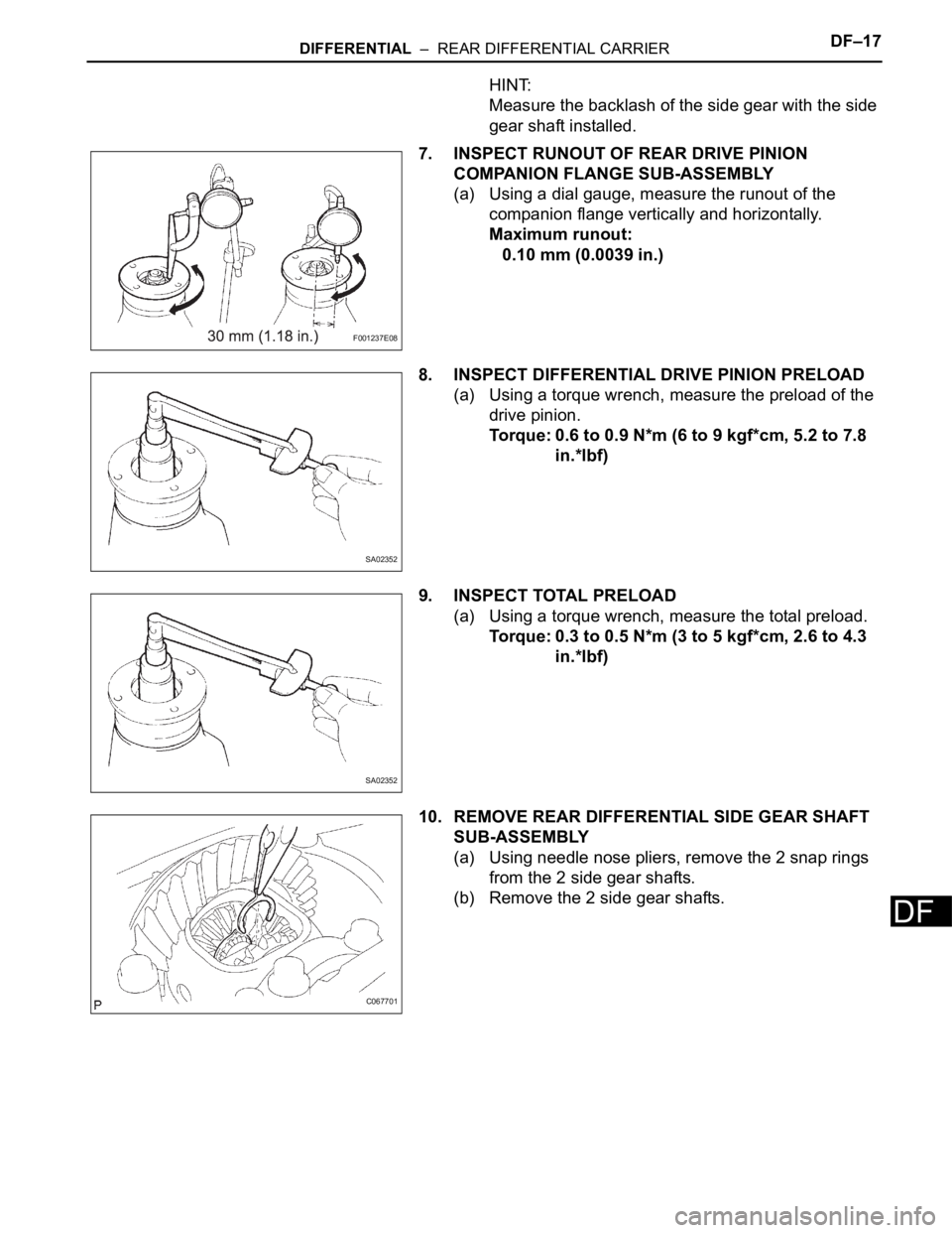
7. INSPECT RUNOUT OF REAR DRIVE PINION
COMPANION FLANGE SUB-ASSEMBLY
(a) Using a dial gauge, measure the runout of the
companion flange vertically and horizontally.
Maximum runout:
0.10 mm (0.0039 in.)
8. INSPECT DIFFERENTIAL DRIVE PINION PRELOAD
(a) Using a torque wrench, measure the preload of the
drive pinion.
Torque: 0.6 to 0.9 N*m (6 to 9 kgf*cm, 5.2 to 7.8
in.*lbf)
9. INSPECT TOTAL PRELOAD
(a) Using a torque wrench, measure the total preload.
Torque: 0.3 to 0.5 N*m (3 to 5 kgf*cm, 2.6 to 4.3
in.*lbf)
10. REMOVE REAR DIFFERENTIAL SIDE GEAR SHAFT
SUB-ASSEMBLY
(a) Using needle nose pliers, remove the 2 snap rings
from the 2 side gear shafts.
(b) Remove the 2 side gear shafts.
F001237E08
SA02352
SA02352
C067701
Page 2140 of 3000
DF–18DIFFERENTIAL – REAR DIFFERENTIAL CARRIER
DF
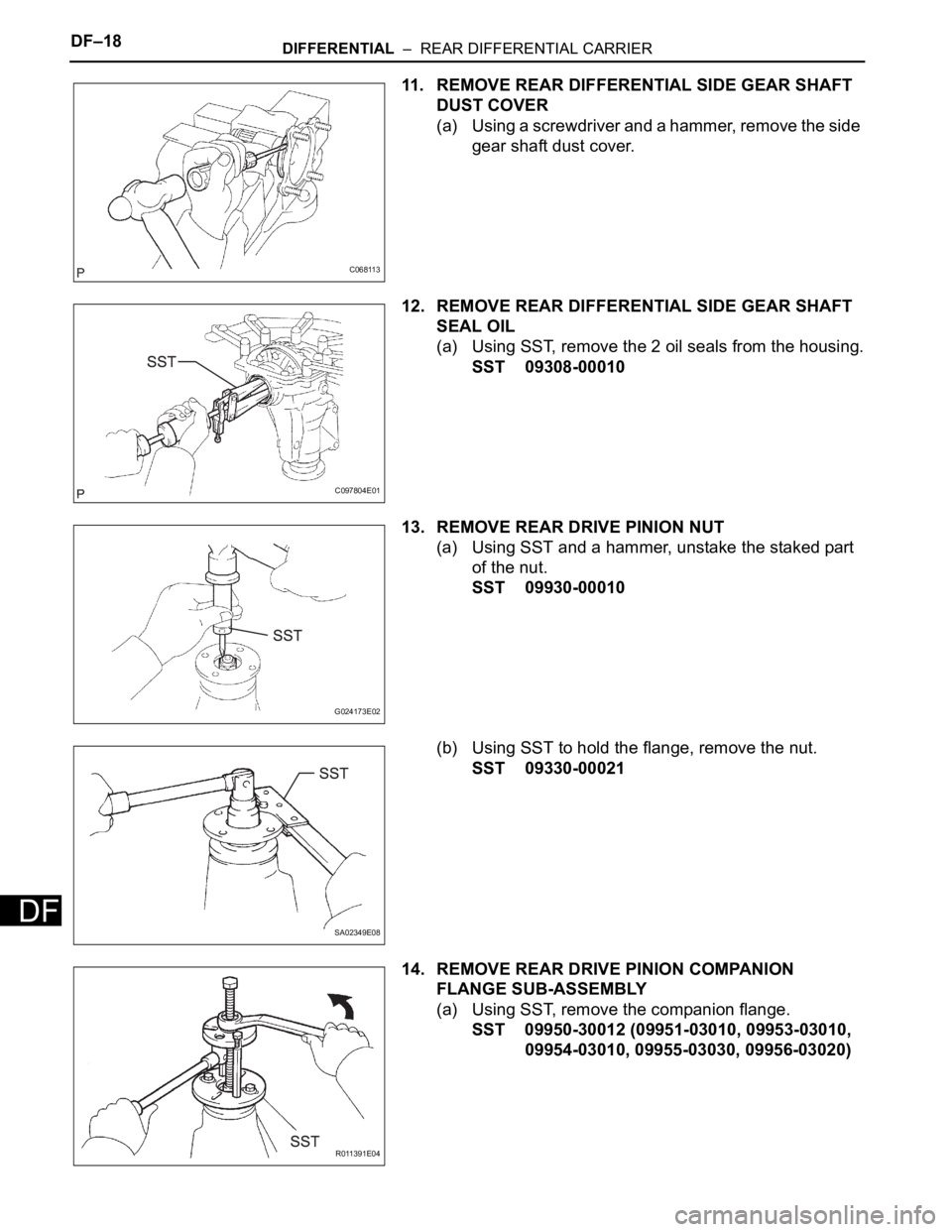
11. REMOVE REAR DIFFERENTIAL SIDE GEAR SHAFT
DUST COVER
(a) Using a screwdriver and a hammer, remove the side
gear shaft dust cover.
12. REMOVE REAR DIFFERENTIAL SIDE GEAR SHAFT
SEAL OIL
(a) Using SST, remove the 2 oil seals from the housing.
SST 09308-00010
13. REMOVE REAR DRIVE PINION NUT
(a) Using SST and a hammer, unstake the staked part
of the nut.
SST 09930-00010
(b) Using SST to hold the flange, remove the nut.
SST 09330-00021
14. REMOVE REAR DRIVE PINION COMPANION
FLANGE SUB-ASSEMBLY
(a) Using SST, remove the companion flange.
SST 09950-30012 (09951-03010, 09953-03010,
09954-03010, 09955-03030, 09956-03020)
C068113
C097804E01
G024173E02
SA02349E08
R011391E04
Trending: hood open, oil level, spark plugs, water pump, checking oil, lights, bulb

