TOYOTA SIENNA 2007 Service Repair Manual
SIENNA 2007
TOYOTA
TOYOTA
https://www.carmanualsonline.info/img/14/57466/w960_57466-0.png
TOYOTA SIENNA 2007 Service Repair Manual
Trending: lights, seat memory, instrument cluster, water pump, open gas tank, low oil pressure, buttons
Page 241 of 3000

TD–8THEFT DETERRENT – THEFT DETERRENT SYSTEM
TD
5. ALARM MEMORY FUNCTION
(a) If the alarm is set off (tampering is detected) while
the theft deterrent system is armed, it will be
recorded by the alarm memory function. Whenever
you cancel the theft deterrent system, the alarm
memory function causes the taillights to light up for
2 seconds in order to inform you that the alarm has
been set off.
(1) Conditions of the alarm memory function that
cause the taillights to light up:
When the theft deterrent system has entered
into the alarm sounding state (tampering has
been detected) even once, the taillights will light
up for 2 seconds if any of the following
conditions is met.
• Switched to the disarmed state from the
armed state during active arming mode.
• Switched to the disarmed state (1) from the
armed state during passive arming mode.
HINT:
Active arming mode: See ACTIVE ARMING
MODE.
Passive arming mode: See PASSIVE ARMING
MODE.
6. PANIC ALARM CONTROL
(a) The panic alarm control makes it possible to
voluntarily set off the panic alarm by pressing the
PANIC switch on the wireless transmitter.
(1) Conditions that cause the panic alarm control to
set off the panic alarm:
The panic alarm control sets off the panic alarm
by pressing the PANIC switch on the wireless
transmitter for over 2, 4 seconds under the
following conditions:
• The ignition switch is OFF.
• The theft deterrent system is not in the alarm
sounding state. (This condition is common
both to active arming mode and to passive
arming mode.)
(2) Conditions that cause the panic alarm control to
shut off the alarm:
The panic alarm control shuts off the panic alarm
when any of the following conditions is met
during panic alarm operation:
• The ignition switch is turned ON.
• Either of the switches on the wireless
transmitter (LOCK/UNLOCK) is pressed.
• The panic alarm ends (60 sec. have passed).
Page 242 of 3000

THEFT DETERRENT – THEFT DETERRENT SYSTEMTD–9
TD
• The theft deterrent system switches to the
alarm sounding state. Under this condition,
the theft deterrent system is controlling the
alarm rather than the panic alarm control. In
order to cancel this alarm, refer to the theft
deterrent system alarm sounding state
cancellation procedure. (This condition is
common both to active arming mode to
passive arming mode.)
HINT:
Active arming mode: See ACTIVE ARMING
MODE.
Passive arming mode: See PASSIVE ARMING
MODE.
7. SECURITY INDICATOR OUTPUT
(a) The multiplex network body ECU outputs a signal to
light up the security indicator, according to the state
of the theft deterrent system. However, some of the
actual lighting conditions of the security indicator
are different from the output signals of the multiplex
network body ECU.
Output:
Blinking cycle:
HINT:
• *: The above condition is common both to active
arming mode and to passive arming mode.
• When the immobiliser system is set, the security
indicator blinks during both the disarmed state
and the armed state, due to the output signals
from the immobiliser system.
State of Theft Deterrent System*Security Indicator
Output Signals from Body ECU Actual Lighting Condition
Disarmed state (1), (2) OFFOFF (Immobiliser system unset)
BLINKING (Immobiliser system set)
Arming preparation state ON ON
Armed state OFF BLINKING
Alarm sounding state ON ON
Time Security Indicator
0.2 sec. ON
1.8 sec. OFF
Page 243 of 3000
ENGINE IMMOBILISER – ENGINE IMMOBILISER SYSTEMEI–3
EI
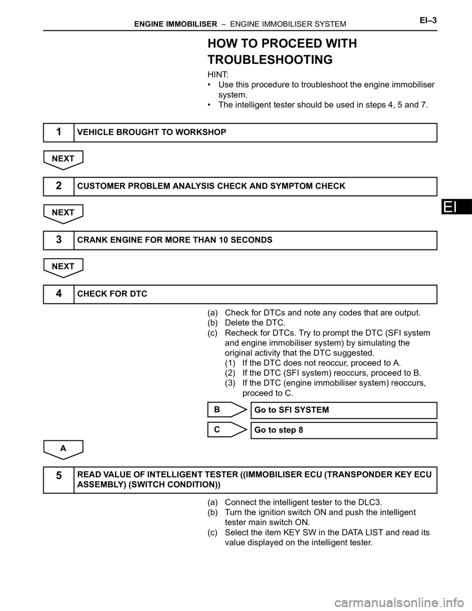
HOW TO PROCEED WITH
TROUBLESHOOTING
HINT:
• Use this procedure to troubleshoot the engine immobiliser
system.
• The intelligent tester should be used in steps 4, 5 and 7.
NEXT
NEXT
NEXT
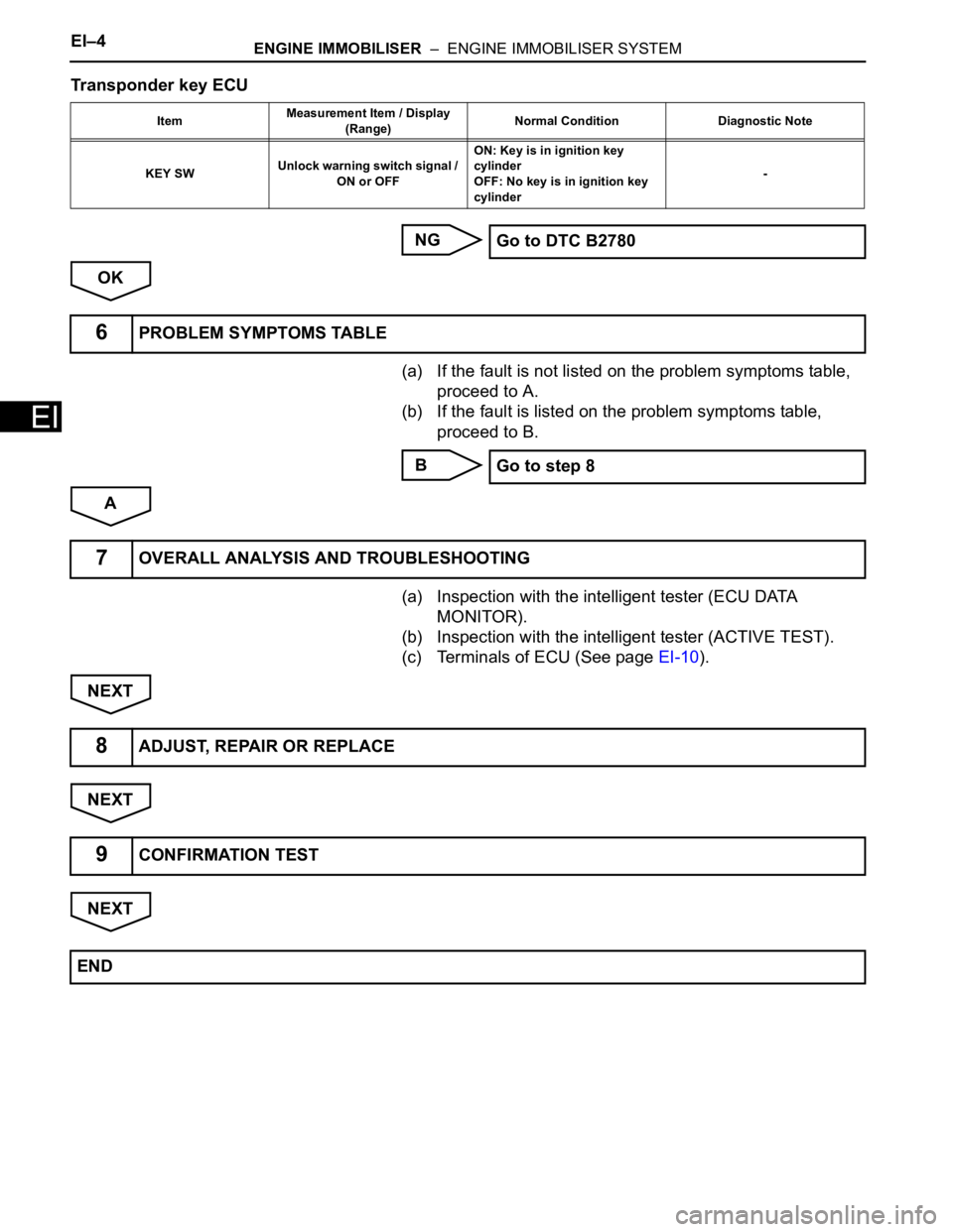
(a) Check for DTCs and note any codes that are output.
(b) Delete the DTC.
(c) Recheck for DTCs. Try to prompt the DTC (SFI system
and engine immobiliser system) by simulating the
original activity that the DTC suggested.
(1) If the DTC does not reoccur, proceed to A.
(2) If the DTC (SFI system) reoccurs, proceed to B.
(3) If the DTC (engine immobiliser system) reoccurs,
proceed to C.
B
C
A
(a) Connect the intelligent tester to the DLC3.
(b) Turn the ignition switch ON and push the intelligent
tester main switch ON.
(c) Select the item KEY SW in the DATA LIST and read its
value displayed on the intelligent tester.
1VEHICLE BROUGHT TO WORKSHOP
2CUSTOMER PROBLEM ANALYSIS CHECK AND SYMPTOM CHECK
3CRANK ENGINE FOR MORE THAN 10 SECONDS
4CHECK FOR DTC
Go to SFI SYSTEM
Go to step 8
5READ VALUE OF INTELLIGENT TESTER ((IMMOBILISER ECU (TRANSPONDER KEY ECU
ASSEMBLY) (SWITCH CONDITION))
Page 244 of 3000
EI–4ENGINE IMMOBILISER – ENGINE IMMOBILISER SYSTEM
EI
Transponder key ECU
NG
OK
(a) If the fault is not listed on the problem symptoms table,
proceed to A.
(b) If the fault is listed on the problem symptoms table,
proceed to B.
B
A
(a) Inspection with the intelligent tester (ECU DATA
MONITOR).
(b) Inspection with the intelligent tester (ACTIVE TEST).
(c) Terminals of ECU (See page EI-10).
NEXT
NEXT
NEXT
ItemMeasurement Item / Display
(Range)Normal Condition Diagnostic Note
KEY SWUnlock warning switch signal /
ON or OFFON: Key is in ignition key
cylinder
OFF: No key is in ignition key
cylinder-
Go to DTC B2780
6PROBLEM SYMPTOMS TABLE
Go to step 8
7OVERALL ANALYSIS AND TROUBLESHOOTING
8ADJUST, REPAIR OR REPLACE
9CONFIRMATION TEST
END
Page 245 of 3000
CRUISE CONTROL – CRUISE CONTROL SYSTEMCC–3
CC
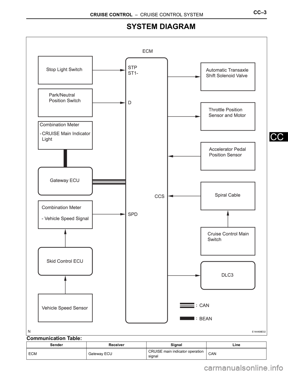
SYSTEM DIAGRAM
Communication Table:
Sender Receiver Signal Line
ECM Gateway ECUCRUISE main indicator operation
signalCAN
E144498E02
Page 246 of 3000
CC–4CRUISE CONTROL – CRUISE CONTROL SYSTEM
CC
Gateway ECU Combination meterCRUISE main indicator operation
signalBEAN Sender Receiver Signal Line
Page 247 of 3000
LIGHTING – LIGHTING SYSTEMLI–5
LI
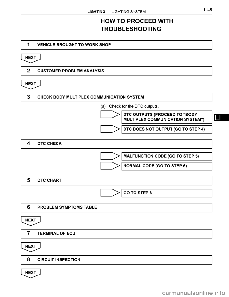
HOW TO PROCEED WITH
TROUBLESHOOTING
NEXT
NEXT
(a) Check for the DTC outputs.
NEXT
NEXT
NEXT
1VEHICLE BROUGHT TO WORK SHOP
2CUSTOMER PROBLEM ANALYSIS
3CHECK BODY MULTIPLEX COMMUNICATION SYSTEM
DTC OUTPUTS (PROCEED TO "BODY
MULTIPLEX COMMUNICATION SYSTEM")
DTC DOES NOT OUTPUT (GO TO STEP 4)
4DTC CHECK
MALFUNCTION CODE (GO TO STEP 5)
NORMAL CODE (GO TO STEP 6)
5DTC CHART
GO TO STEP 8
6PROBLEM SYMPTOMS TABLE
7TERMINAL OF ECU
8CIRCUIT INSPECTION
Page 248 of 3000
LI–6LIGHTING – LIGHTING SYSTEM
LI
NEXT
NEXT
NEXT
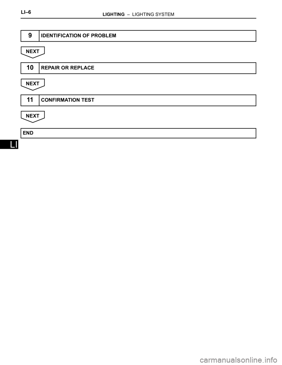
9IDENTIFICATION OF PROBLEM
10REPAIR OR REPLACE
11CONFIRMATION TEST
END
Page 249 of 3000
LI–104LIGHTING – HEADLIGHT DIMMER SWITCH
LI
INSTALLATION
1. INSTALL HEADLIGHT DIMMER SWITCH ASSEMBLY
2. INSTALL STEERING COLUMN UPPER COVER
3. INSTALL STEERING COLUMN LOWER COVER
Page 250 of 3000
WW–6WIPER AND WASHER – FRONT WIPER MOTOR
WW
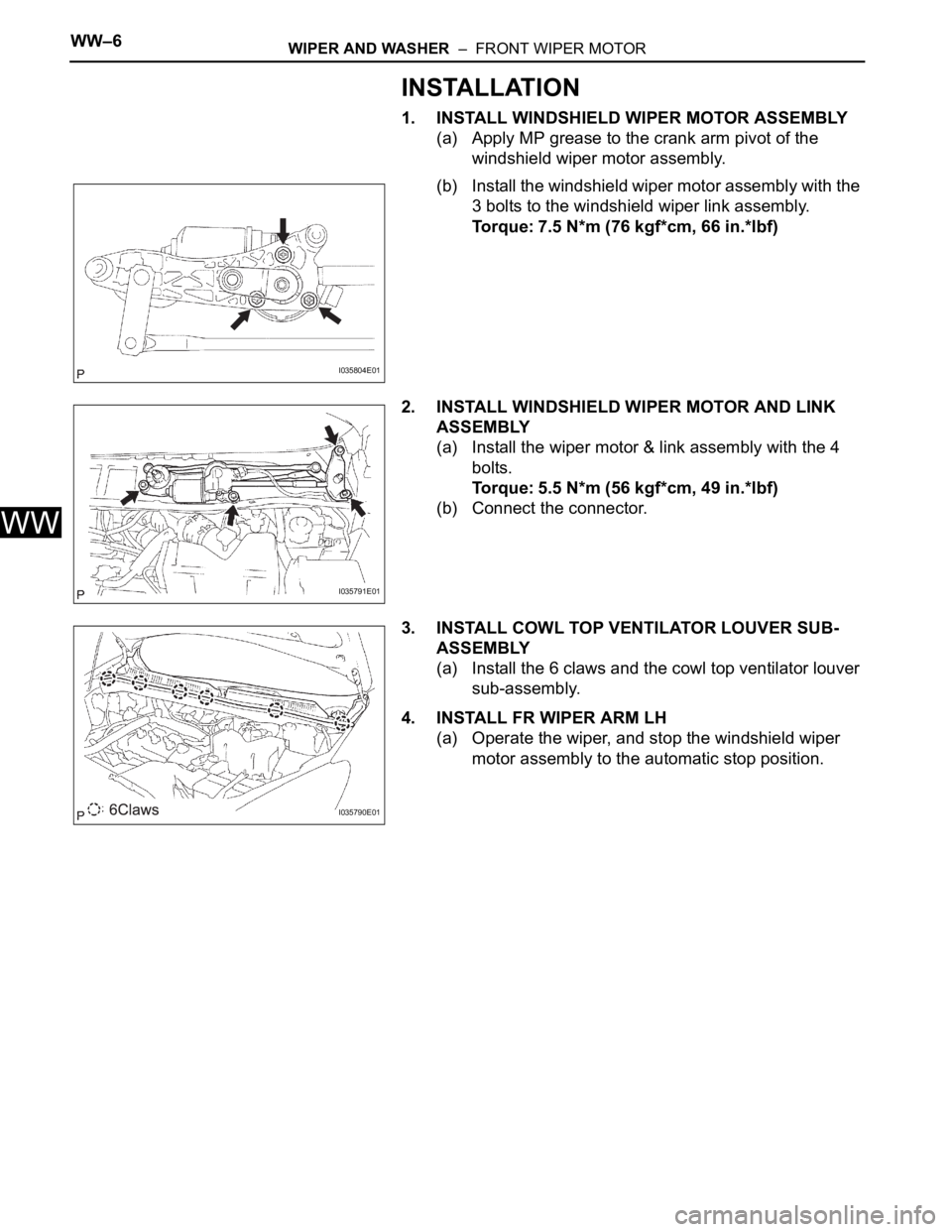
INSTALLATION
1. INSTALL WINDSHIELD WIPER MOTOR ASSEMBLY
(a) Apply MP grease to the crank arm pivot of the
windshield wiper motor assembly.
(b) Install the windshield wiper motor assembly with the
3 bolts to the windshield wiper link assembly.
Torque: 7.5 N*m (76 kgf*cm, 66 in.*lbf)
2. INSTALL WINDSHIELD WIPER MOTOR AND LINK
ASSEMBLY
(a) Install the wiper motor & link assembly with the 4
bolts.
Torque: 5.5 N*m (56 kgf*cm, 49 in.*lbf)
(b) Connect the connector.
3. INSTALL COWL TOP VENTILATOR LOUVER SUB-
ASSEMBLY
(a) Install the 6 claws and the cowl top ventilator louver
sub-assembly.
4. INSTALL FR WIPER ARM LH
(a) Operate the wiper, and stop the windshield wiper
motor assembly to the automatic stop position.
I035804E01
I035791E01
I035790E01
Trending: coolant, fuse chart, ignition circuit, clock, Hoses, engine oil, ecu wiring


