TOYOTA SIENNA 2007 Service Repair Manual
SIENNA 2007
TOYOTA
TOYOTA
https://www.carmanualsonline.info/img/14/57466/w960_57466-0.png
TOYOTA SIENNA 2007 Service Repair Manual
Trending: fuel type, horn, Dash, immobilizer, ball joint, recommended oil, width
Page 291 of 3000
INSTRUMENT PANEL – INSTRUMENT PANEL SAFETY PADIP–7
IP
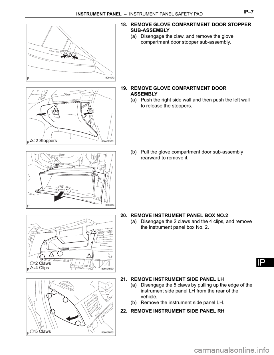
18. REMOVE GLOVE COMPARTMENT DOOR STOPPER
SUB-ASSEMBLY
(a) Disengage the claw, and remove the glove
compartment door stopper sub-assembly.
19. REMOVE GLOVE COMPARTMENT DOOR
ASSEMBLY
(a) Push the right side wall and then push the left wall
to release the stoppers.
(b) Pull the glove compartment door sub-assembly
rearward to remove it.
20. REMOVE INSTRUMENT PANEL BOX NO.2
(a) Disengage the 2 claws and the 4 clips, and remove
the instrument panel box No. 2.
21. REMOVE INSTRUMENT SIDE PANEL LH
(a) Disengage the 5 claws by pulling up the edge of the
instrument side panel LH from the rear of the
vehicle.
(b) Remove the instrument side panel LH.
22. REMOVE INSTRUMENT SIDE PANEL RH
B066072
B066073E01
B066074
B066075E01
B066076E01
Page 292 of 3000
IP–8INSTRUMENT PANEL – INSTRUMENT PANEL SAFETY PAD
IP
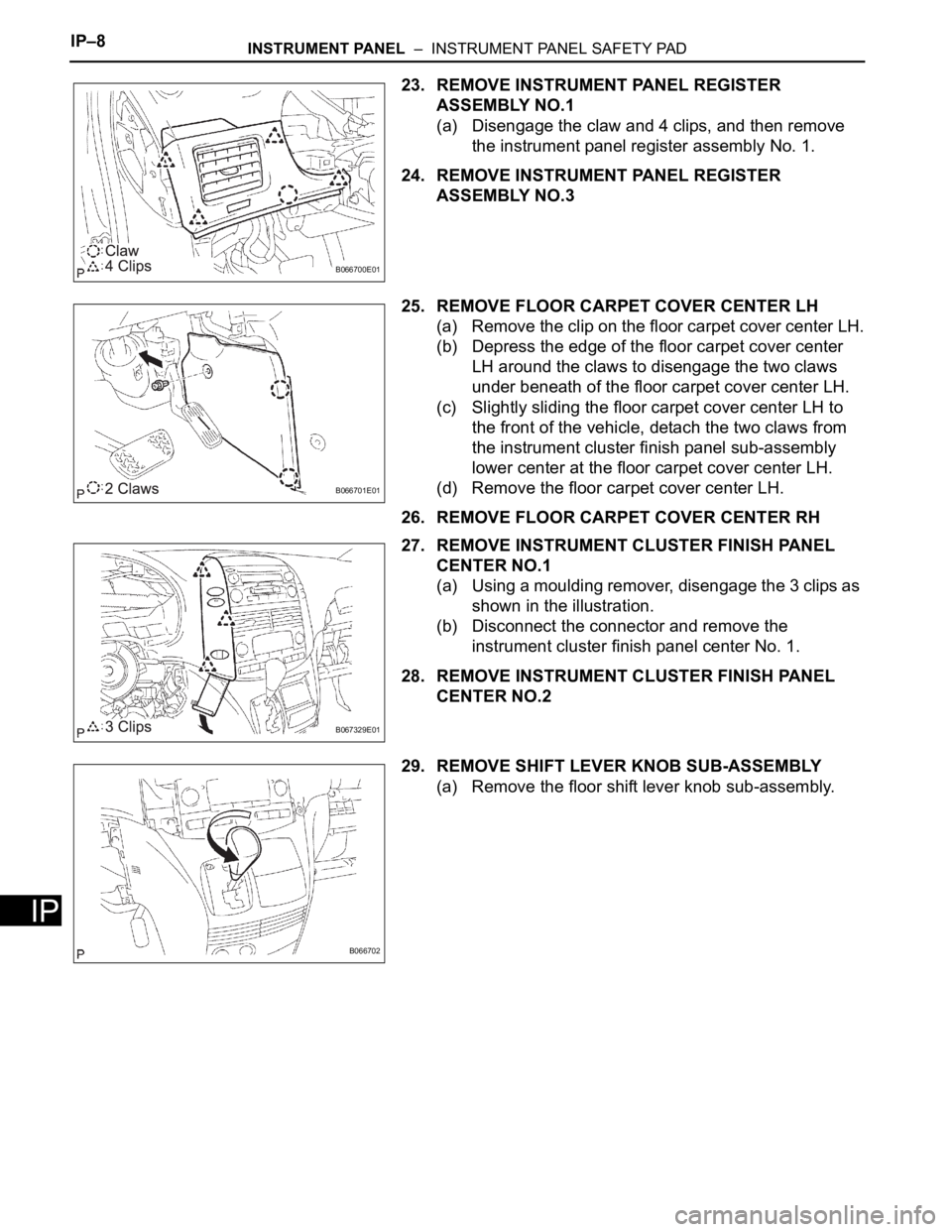
23. REMOVE INSTRUMENT PANEL REGISTER
ASSEMBLY NO.1
(a) Disengage the claw and 4 clips, and then remove
the instrument panel register assembly No. 1.
24. REMOVE INSTRUMENT PANEL REGISTER
ASSEMBLY NO.3
25. REMOVE FLOOR CARPET COVER CENTER LH
(a) Remove the clip on the floor carpet cover center LH.
(b) Depress the edge of the floor carpet cover center
LH around the claws to disengage the two claws
under beneath of the floor carpet cover center LH.
(c) Slightly sliding the floor carpet cover center LH to
the front of the vehicle, detach the two claws from
the instrument cluster finish panel sub-assembly
lower center at the floor carpet cover center LH.
(d) Remove the floor carpet cover center LH.
26. REMOVE FLOOR CARPET COVER CENTER RH
27. REMOVE INSTRUMENT CLUSTER FINISH PANEL
CENTER NO.1
(a) Using a moulding remover, disengage the 3 clips as
shown in the illustration.
(b) Disconnect the connector and remove the
instrument cluster finish panel center No. 1.
28. REMOVE INSTRUMENT CLUSTER FINISH PANEL
CENTER NO.2
29. REMOVE SHIFT LEVER KNOB SUB-ASSEMBLY
(a) Remove the floor shift lever knob sub-assembly.
B066700E01
B066701E01
B067329E01
B066702
Page 293 of 3000
Page 294 of 3000
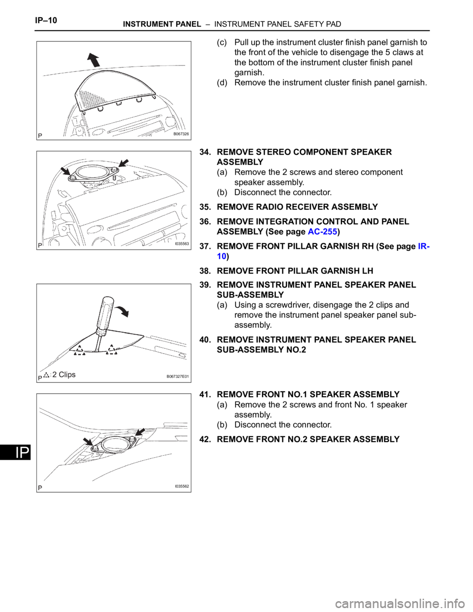
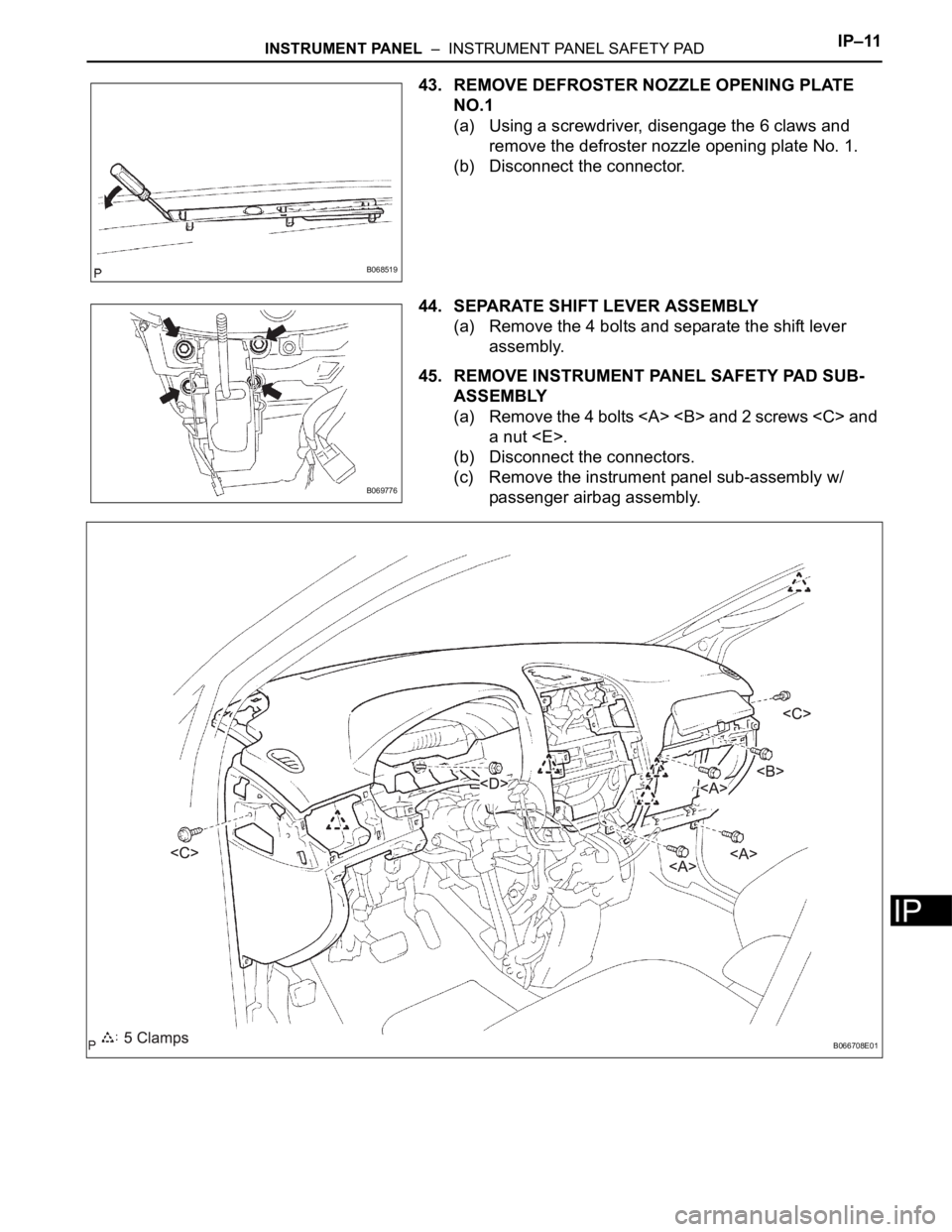
IP–10INSTRUMENT PANEL – INSTRUMENT PANEL SAFETY PAD
IP
(c) Pull up the instrument cluster finish panel garnish to
the front of the vehicle to disengage the 5 claws at
the bottom of the instrument cluster finish panel
garnish.
(d) Remove the instrument cluster finish panel garnish.
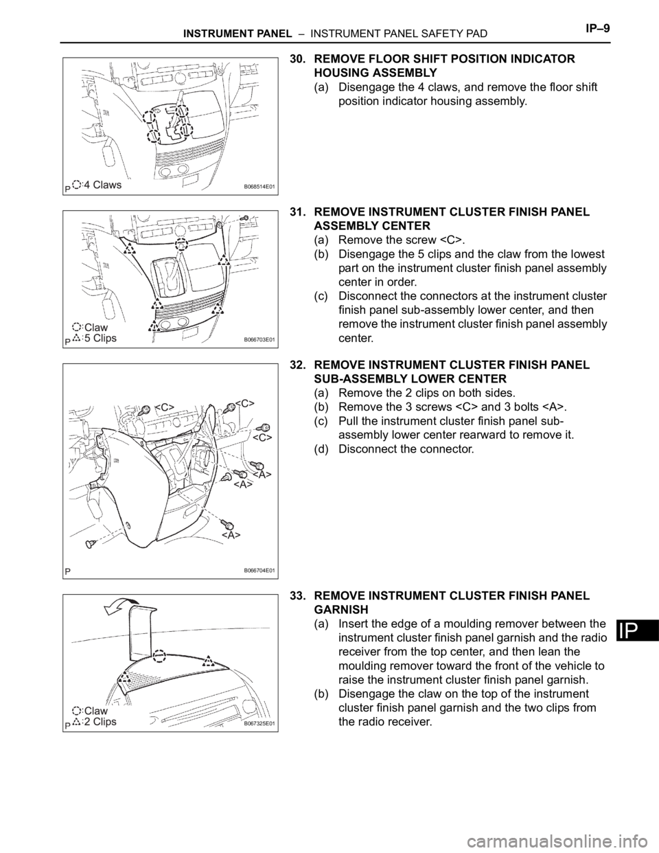
34. REMOVE STEREO COMPONENT SPEAKER
ASSEMBLY
(a) Remove the 2 screws and stereo component
speaker assembly.
(b) Disconnect the connector.
35. REMOVE RADIO RECEIVER ASSEMBLY
36. REMOVE INTEGRATION CONTROL AND PANEL
ASSEMBLY (See page AC-255)
37. REMOVE FRONT PILLAR GARNISH RH (See page IR-
10)
38. REMOVE FRONT PILLAR GARNISH LH
39. REMOVE INSTRUMENT PANEL SPEAKER PANEL
SUB-ASSEMBLY
(a) Using a screwdriver, disengage the 2 clips and
remove the instrument panel speaker panel sub-
assembly.
40. REMOVE INSTRUMENT PANEL SPEAKER PANEL
SUB-ASSEMBLY NO.2
41. REMOVE FRONT NO.1 SPEAKER ASSEMBLY
(a) Remove the 2 screws and front No. 1 speaker
assembly.
(b) Disconnect the connector.
42. REMOVE FRONT NO.2 SPEAKER ASSEMBLY
B067326
I035563
B067327E01
I035562
Page 295 of 3000
Page 296 of 3000
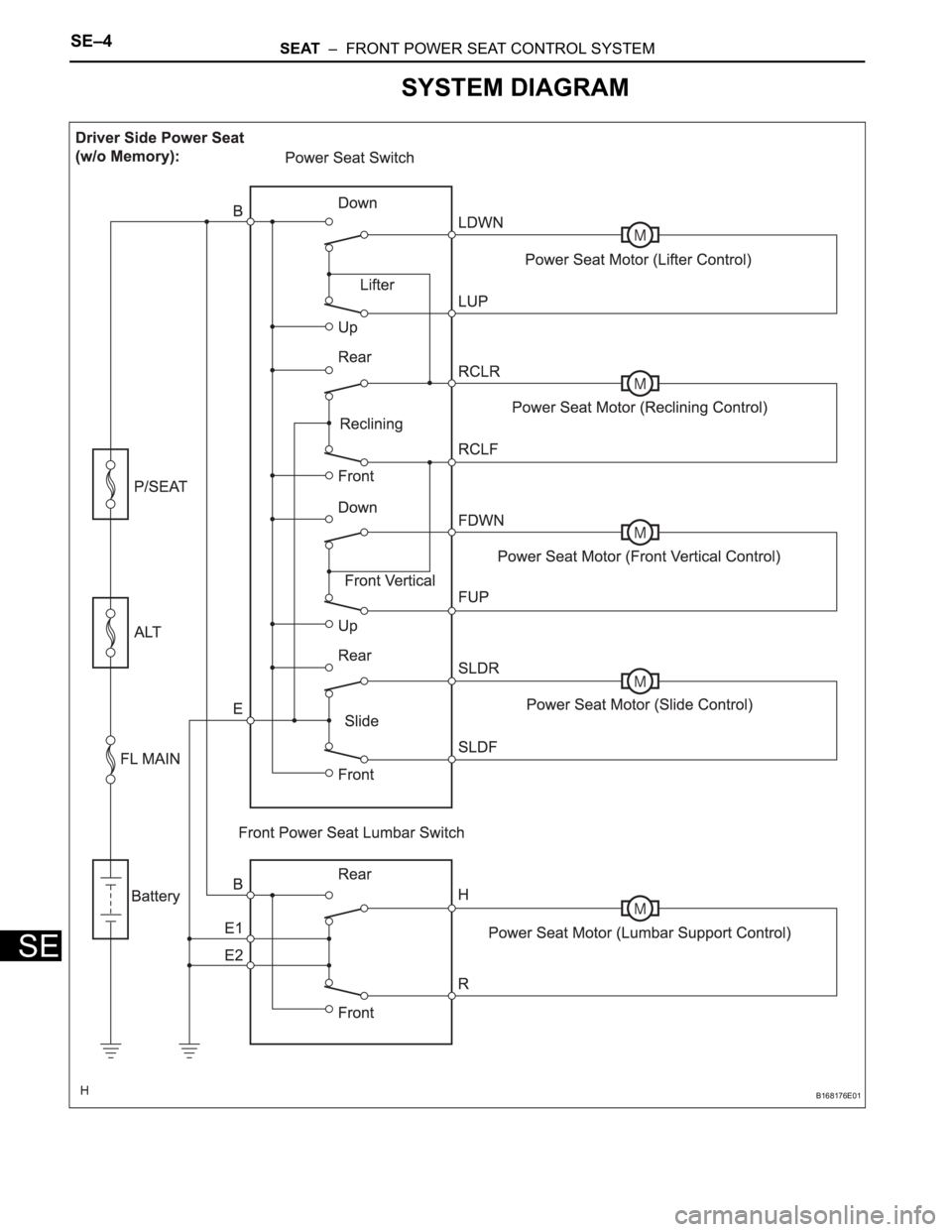
SE–4SEAT – FRONT POWER SEAT CONTROL SYSTEM
SE
SYSTEM DIAGRAM
B168176E01
Page 297 of 3000
SEAT – FRONT POWER SEAT CONTROL SYSTEMSE–5
SE
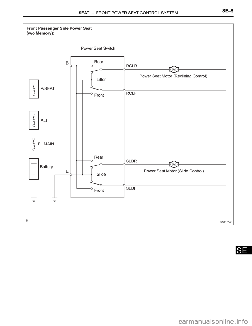
B168177E01
Page 298 of 3000
SE–6SEAT – FRONT POWER SEAT CONTROL SYSTEM
SE
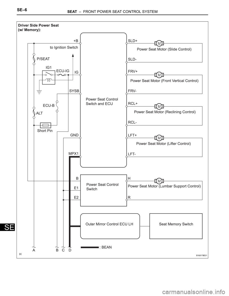
B168178E01
Page 299 of 3000
SEAT – FRONT POWER SEAT CONTROL SYSTEMSE–7
SE
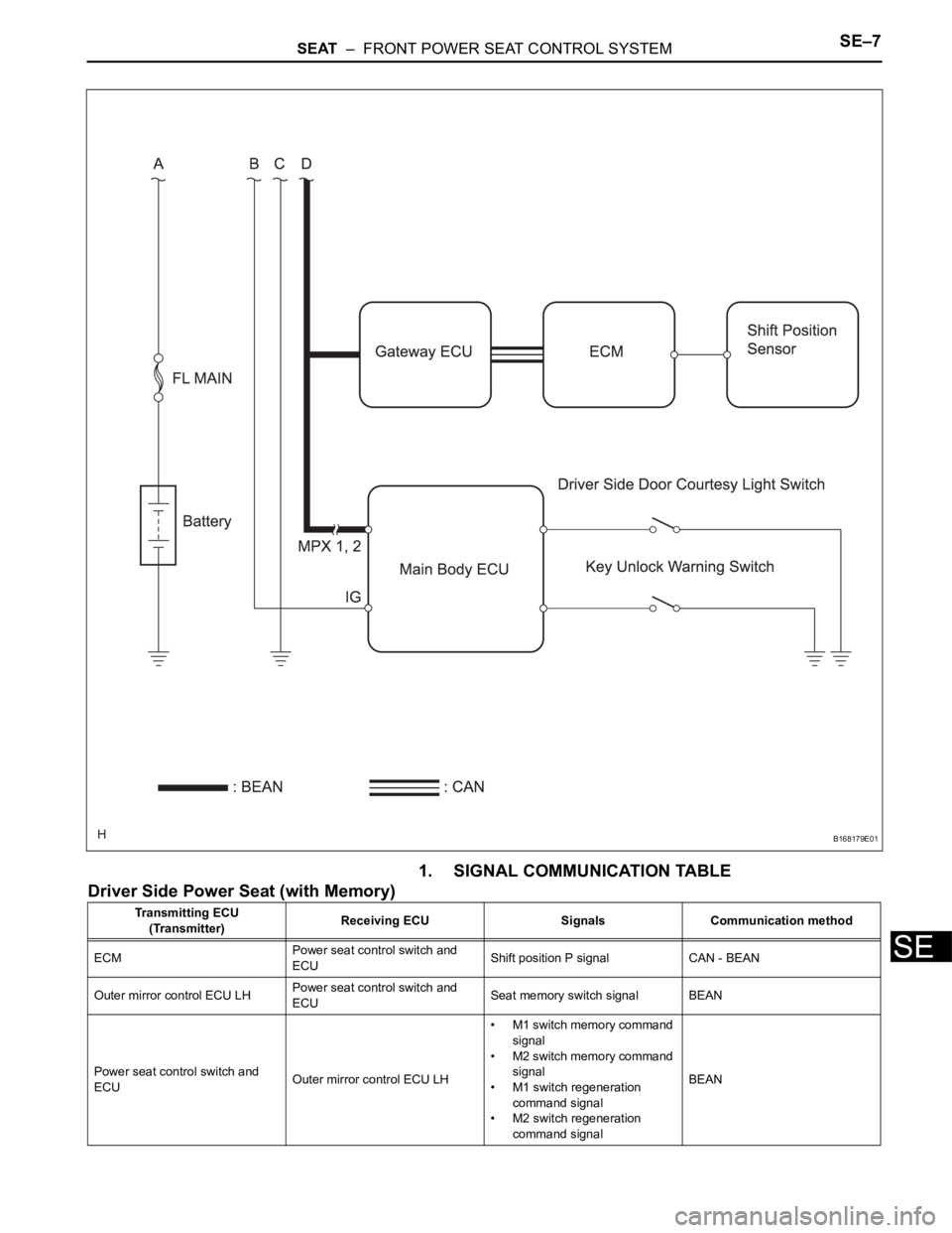
1. SIGNAL COMMUNICATION TABLE
Driver Side Power Seat (with Memory)
B168179E01
Transmitting ECU
(Transmitter)Receiving ECU Signals Communication method
ECMPower seat control switch and
ECUShift position P signal CAN - BEAN
Outer mirror control ECU LHPower seat control switch and
ECUSeat memory switch signal BEAN
Power seat control switch and
ECUOuter mirror control ECU LH• M1 switch memory command
signal
• M2 switch memory command
signal
• M1 switch regeneration
command signal
• M2 switch regeneration
command signalBEAN
Page 300 of 3000
SE–8SEAT – FRONT POWER SEAT CONTROL SYSTEM
SE
Main body ECUPower seat control switch and
ECU• Driver side door courtesy light
switch signal
• Key unlock warning switch
signal
• Ignition switch signalBEAN Transmitting ECU
(Transmitter)Receiving ECU Signals Communication method
Trending: tire size, battery replacement, fuse chart, door lock, fuses, Transaxle, fuel tank removal
