VOLKSWAGEN PASSAT 1995 B3, B4 / 3.G Service Workshop Manual
PASSAT 1995 B3, B4 / 3.G
VOLKSWAGEN
VOLKSWAGEN
https://www.carmanualsonline.info/img/18/7419/w960_7419-0.png
VOLKSWAGEN PASSAT 1995 B3, B4 / 3.G Service Workshop Manual
Trending: display, air bleeding, air suspension, length, ECU, brake pads, wheelbase
Page 281 of 369
Downloaded from www.Manualslib.com manuals search engine 48-11
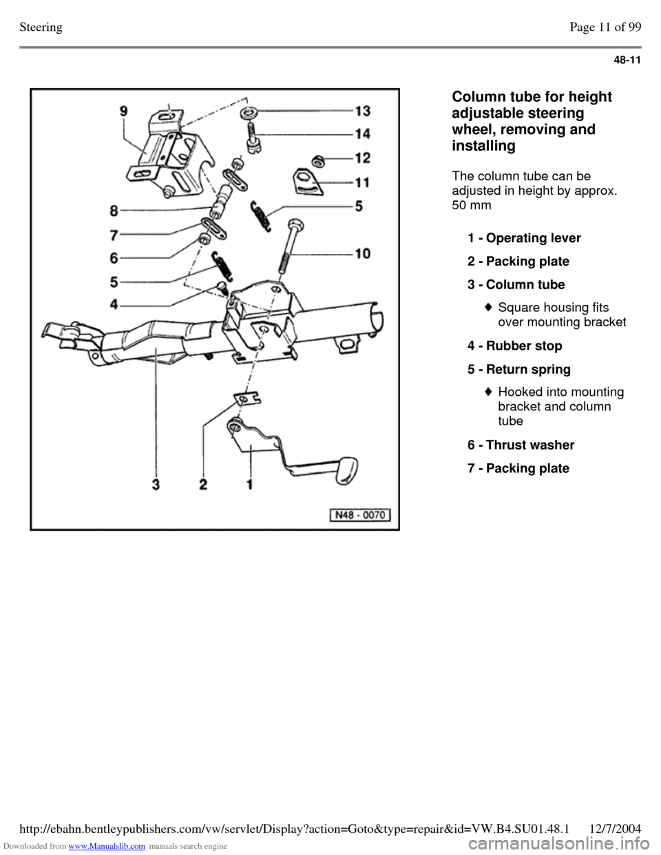
Column tube for height
adjustable steering
wheel, removing and
installing
The column tube can be
adjusted in height by approx.
50 mm
1 - Operating lever
2 - Packing plate
3 - Column tube Square housing fits
over mounting bracket
4 - Rubber stop
5 - Return spring Hooked into mounting
bracket and column
tube
6 - Thrust washer
7 - Packing plate Page 11 of 99Steering12/7/2004http://ebahn.bentleypublishers.com/vw/servlet/Display?action=Goto&type=repair&id=VW.B4.SU01.48.1
Page 282 of 369
Downloaded from www.Manualslib.com manuals search engine 48-12
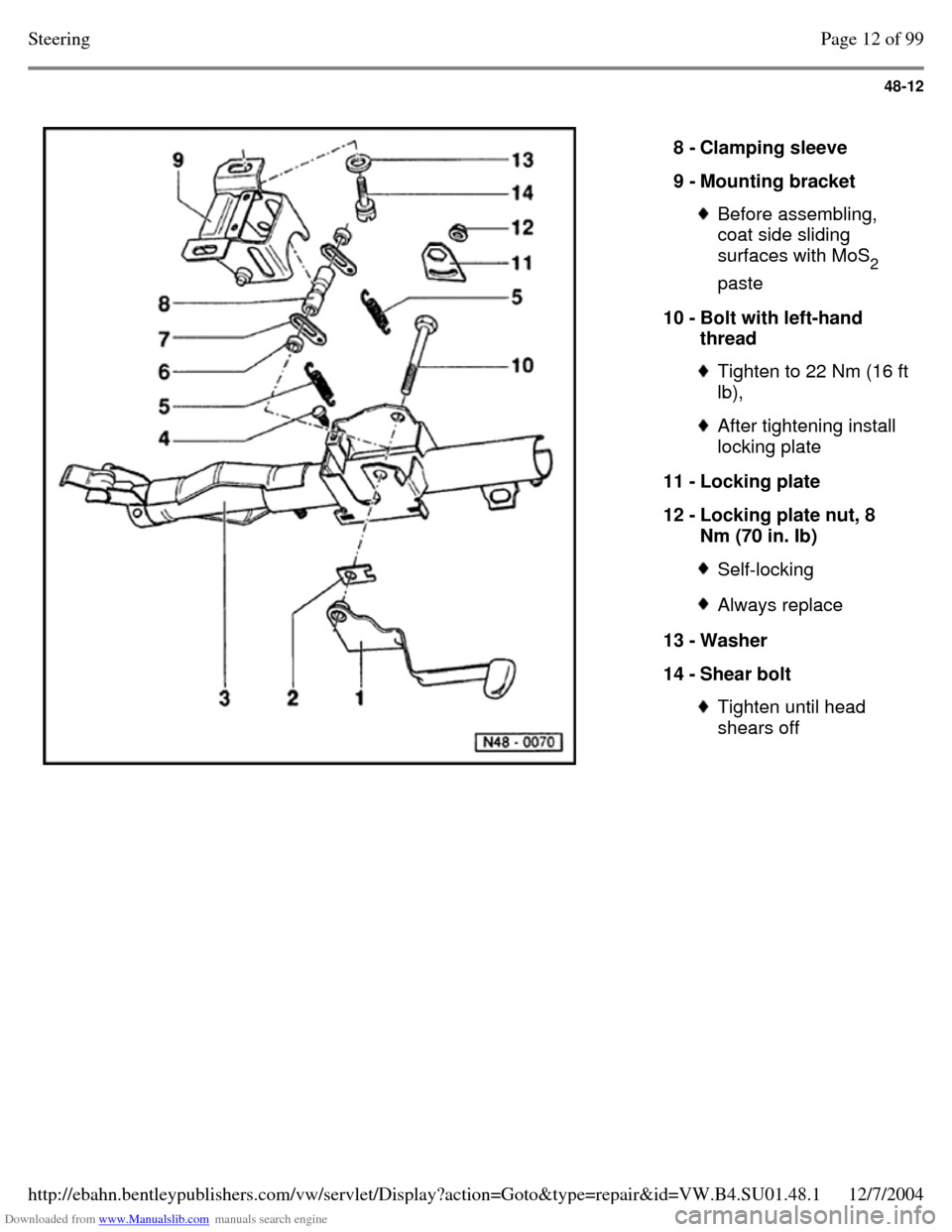
8 - Clamping sleeve
9 - Mounting bracket Before assembling,
coat side sliding
surfaces with MoS
2
paste
10 - Bolt with left-hand
thread Tighten to 22 Nm (16 ft lb), After tightening install
locking plate
11 - Locking plate
12 - Locking plate nut, 8
Nm (70 in. Ib) Self-locking Always replace 13 - Washer
14 - Shear bolt Tighten until head
shears off Page 12 of 99Steering12/7/2004http://ebahn.bentleypublishers.com/vw/servlet/Display?action=Goto&type=repair&id=VW.B4.SU01.48.1
Page 283 of 369
Downloaded from www.Manualslib.com manuals search engine 48-13
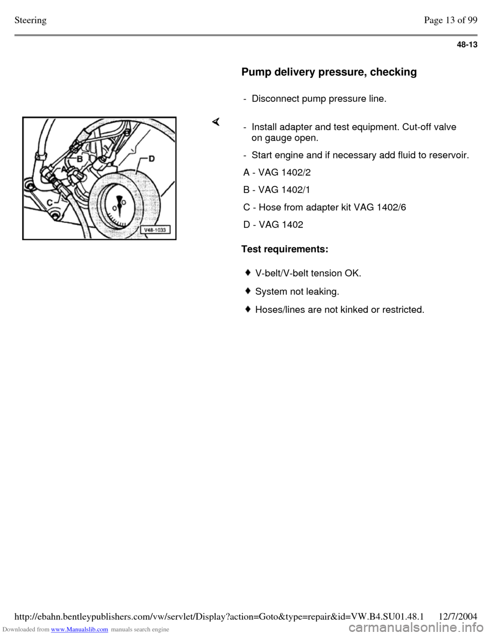
Pump delivery pressure, checking
- Disconnect pump pressure line. Test requirements: - Install adapter and test equipment. Cut-off valve
on gauge open.
- Start engine and if necessary add fluid to reservoir. A - VAG 1402/2 B - VAG 1402/1 C - Hose from adapter kit VAG 1402/6 D - VAG 1402 V-belt/V-belt tension OK. System not leaking. Hoses/lines are not kinked or restricted. Page 13 of 99Steering12/7/2004http://ebahn.bentleypublishers.com/vw/servlet/Display?action=Goto&type=repair&id=VW.B4.SU01.48.1
Page 284 of 369
Downloaded from www.Manualslib.com manuals search engine 48-14
- With engine running at idling speed. Close cut-
off valve (not longer than 5 seconds) and read
off pressure.
Specification: 85 - 95 bar (1232 - 1377
psi)
Note:
If the reading is higher or lower than specified
replace pump.
Vehicles with up to 110 kW engine Page 48-90 . Vehicles with 128 kW engine Page 48-97 . If reservoir fluid level is low then check steering
system for leaks.
For leaks at the pinion first check the lines/line
connections for leaks and if necessary tighten
and wipe dry.
If the pinion seal or the rack seals in steering
box housing are leaking then replace steering
gear.
To check the rack seals loosen the clamp on
the boot and push to one side. Page 14 of 99Steering12/7/2004http://ebahn.bentleypublishers.com/vw/servlet/Display?action=Goto&type=repair&id=VW.B4.SU01.48.1
Page 285 of 369
Downloaded from www.Manualslib.com manuals search engine 48-15
Power steering gear, removing and
installing
When working on the power assisted steering
gear:
Absolute cleanliness is required when working
on the power steering.
Thoroughly clean connections and immediate
vicinity before loosening.
Place parts on a clean surface and cover if not
re-installing immediately.
Do not use fluffy cloths. Only unpack parts immediately prior to
installation.
Only use genuine packed parts. Vehicles with four wheel drive observe installing heat shield. Page 15 of 99Steering12/7/2004http://ebahn.bentleypublishers.com/vw/servlet/Display?action=Goto&type=repair&id=VW.B4.SU01.48.1
Page 286 of 369
Downloaded from www.Manualslib.com manuals search engine 48-16
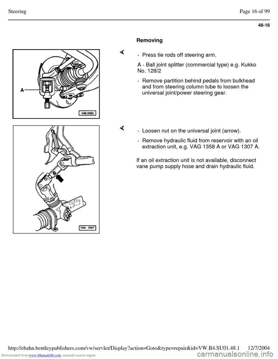
Removing - Press tie rods off steering arm. A - Ball joint splitter (commercial type) e.g. Kukko
No. 128/2
- Remove partition behind pedals from bulkhead
and from steering column tube to loosen the
universal joint/power steering gear. If an oil extraction unit is not available, disconnect
vane pump supply hose and drain hydraulic fluid. - Loosen nut on the universal joint (arrow). - Remove hydraulic fluid from reservoir with an oil
extraction unit, e.g. VAG 1358 A or VAG 1307 A. Page 16 of 99Steering12/7/2004http://ebahn.bentleypublishers.com/vw/servlet/Display?action=Goto&type=repair&id=VW.B4.SU01.48.1
Page 287 of 369
Downloaded from www.Manualslib.com manuals search engine 48-17
Instead of plastic sealing plugs a plug consisting of
Part No.113 301 229 A and banjo bolt, Part No. N
904 674 01 can be used. But when using these,
several 16 mm diameter sealing rings must be used
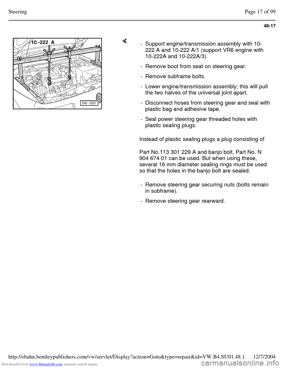
so that the holes in the banjo bolt are sealed. - Support engine/transmission assembly with 10-
222 A and 10-222 A/1 (support VR6 engine with
10-222A and 10-222A/3).
- Remove boot from seat on steering gear. - Remove subframe bolts. - Lower engine/transmission assembly; this will pull
the two halves of the universal joint apart.
- Disconnect hoses from steering gear and seal with plastic bag and adhesive tape.
- Seal power steering gear threaded holes with
plastic sealing plugs.
- Remove steering gear securing nuts (bolts remain
in subframe).
- Remove steering gear rearward. Page 17 of 99Steering12/7/2004http://ebahn.bentleypublishers.com/vw/servlet/Display?action=Goto&type=repair&id=VW.B4.SU01.48.1
Page 288 of 369
Downloaded from www.Manualslib.com manuals search engine 48-18
Installing
Install in reverse order.
- Check position of steering wheel and, if
necessary, align front end.
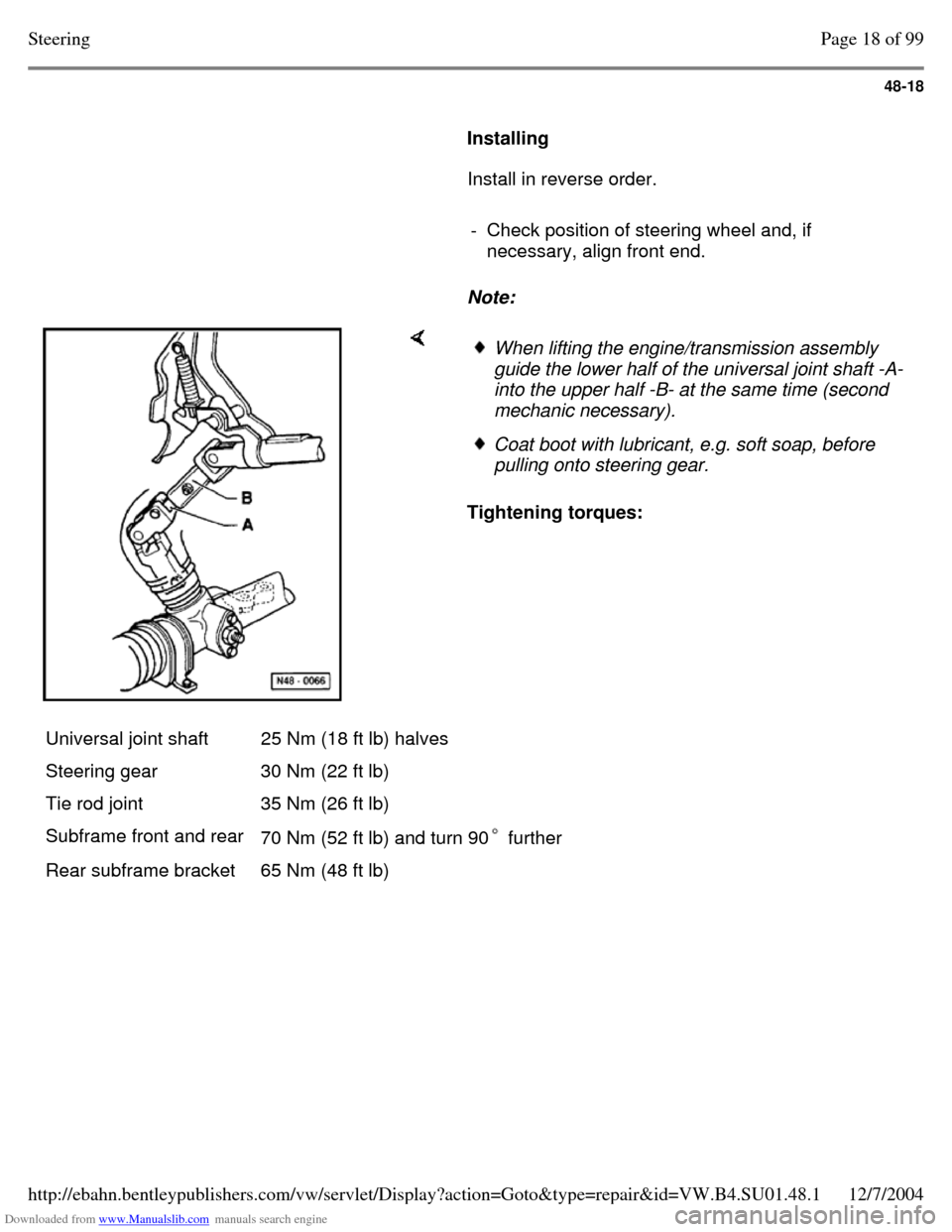
Note: Tightening torques: When lifting the engine/transmission assembly
guide the lower half of the universal joint shaft -A-
into the upper half -B- at the same time (second
mechanic necessary). Coat boot with lubricant, e.g. soft soap, before
pulling onto steering gear.
Universal joint shaft 25 Nm (18 ft lb) halves
Steering gear 30 Nm (22 ft lb)
Tie rod joint 35 Nm (26 ft lb)
Subframe front and rear
70 Nm (52 ft lb) and turn 90 further Rear subframe bracket 65 Nm (48 ft lb) Page 18 of 99Steering12/7/2004http://ebahn.bentleypublishers.com/vw/servlet/Display?action=Goto&type=repair&id=VW.B4.SU01.48.1
Page 289 of 369
Downloaded from www.Manualslib.com manuals search engine 48-19
Assembly overview: power assisted
steering box (TRW)
Determine cause of any malfunctions using
pressure and leak testing, Page 48-13 .
Note:
Always replace self-locking nuts and bolts. Welding and straightening work on steering
components is not permitted.
To grease the rack only use steering gear
grease, Part No. AOF 063 000 04.
Type of oil: Hydraulic oil G 002 000 Oil system capacity: 0.7 - 0.9 ltr. (0.74 - 0.95
qt)
Supply and pressure line routing from Page 48-85 . Page 19 of 99Steering12/7/2004http://ebahn.bentleypublishers.com/vw/servlet/Display?action=Goto&type=repair&id=VW.B4.SU01.48.1
Page 290 of 369
Downloaded from www.Manualslib.com manuals search engine 48-20
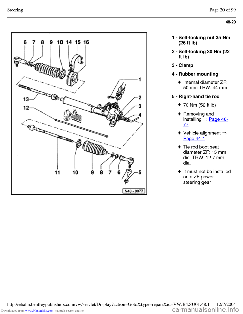
1 - Self-locking nut 35 Nm
(26 ft lb)
2 - Self-locking 30 Nm (22
ft lb)
3 - Clamp
4 - Rubber mounting Internal diameter ZF:
50 mm TRW: 44 mm
5 - Right-hand tie rod 70 Nm (52 ft lb) Removing and
installing Page 48-77 Vehicle alignment
Page 44-1 Tie rod boot seat
diameter ZF: 15 mm
dia. TRW: 12.7 mm
dia. It must not be installed
on a ZF power
steering gear Page 20 of 99Steering12/7/2004http://ebahn.bentleypublishers.com/vw/servlet/Display?action=Goto&type=repair&id=VW.B4.SU01.48.1
Trending: teves, engine coolant, drain bolt, weight, oil pressure, air bleeding, brake sensor
