overheating VOLVO XC60 TWIN ENGINE 2019 Owners Manual
[x] Cancel search | Manufacturer: VOLVO, Model Year: 2019, Model line: XC60 TWIN ENGINE, Model: VOLVO XC60 TWIN ENGINE 2019Pages: 695, PDF Size: 14.96 MB
Page 12 of 695
10
STARTING AND DRIVING
Starting the vehicle430
Switching off the vehicle432
Ignition modes433
Selecting ignition mode434
Brake functions434
Brakes435
Brake Assist System437
Braking on wet roads437
Braking on salted roads437
Maintenance of the brake system438
Parking brake438
Activating and deactivating the park-ing brake439
Settings for automatically activatingthe parking brake440
Parking on a hill440
Parking brake malfunction441
Auto-hold brakes442
Activating and deactivating Auto-hold at a standstill442
Hill Start Assist443
Braking assist after a collision443
Transmission444
Gear selector positions for automatictransmissions445
Using the steering wheel paddles* toshift447
Shiftlock448
The kickdown function448
All Wheel Drive (AWD)448
Drive systems449
Starting and stopping the combus-tion engine in Twin Engine vehicles450
Drive modes450
Changing drive mode455
Energy distribution in hybrid modeusing map data*456
Leveling control* and suspension457
Leveling control settings*460
Low Speed Control460
Activating and deactivating LowSpeed Control using the function button461
Hill Descent Control462
Activating and deactivating HillDescent Control using the functionbutton
463
Economical driving463
Using the electric motor only465
Factors affecting electric motor range465
"Hold" and "Charge" functions467
Preparing for a long trip468
Winter driving468
Driving through standing water469
Opening/closing the fuel filler door470
Refueling471
Fuel472
Octane rating473
Emission controls475
Overheating of engine and transmission475
Battery drain476
Jump starting using another battery477
Detachable towbar*478
Driving with a trailer479
Trailer Stability Assist*481
Checking trailer lights482
Towing using a towline483
Attaching and removing the towing eyelet484
Recovery485
HomeLink®*485
Programming HomeLink®*486
Using HomeLink®*487
Type approval for HomeLink®*488
Compass*489
Activating and deactivating the compass*489
Calibrating the compass*489
Page 182 of 695
WINDOWS, GLASS AND MIRRORS
180
Using the rear window wiper/washer
The rear window wiper/washer cleans the rearwindow. Use the right-side steering wheel leverto start and control the wiper/washer.
Activating the rear window wiper/
washer
NOTE
The rear window wiper motor is equipped withoverheating protection that switches off themotor if it becomes overheated. The rear win-dow wiper can be operated again after a cool-ing-down period.
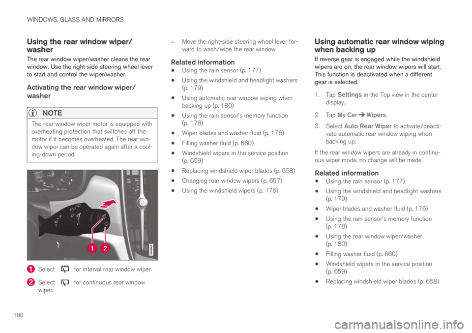
Select for interval rear window wiper.
Select for continuous rear windowwiper.
–Move the right-side steering wheel lever for-ward to wash/wipe the rear window.
Related information
Using the rain sensor (p. 177)
Using the windshield and headlight washers(p. 179)
Using automatic rear window wiping whenbacking up (p. 180)
Using the rain sensor's memory function(p. 178)
Wiper blades and washer fluid (p. 176)
Filling washer fluid (p. 660)
Windshield wipers in the service position(p. 659)
Replacing windshield wiper blades (p. 658)
Changing rear window wipers (p. 657)
Using the windshield wipers (p. 176)
Using automatic rear window wipingwhen backing up
If reverse gear is engaged while the windshieldwipers are on, the rear window wipers will start.This function is deactivated when a differentgear is selected.
1.Tap Settings in the Top view in the centerdisplay.
2.Tap My CarWipers.
3.Select Auto Rear Wiper to activate/deacti-vate automatic rear window wiping whenbacking up.
If the rear window wipers are already in continu-ous wiper mode, no change will be made.
Related information
Using the rain sensor (p. 177)
Using the windshield and headlight washers(p. 179)
Wiper blades and washer fluid (p. 176)
Using the rain sensor's memory function(p. 178)
Using the rear window wiper/washer(p. 180)
Filling washer fluid (p. 660)
Windshield wipers in the service position(p. 659)
Replacing windshield wiper blades (p. 658)
Page 325 of 695
DRIVER SUPPORT
}}
* Option/accessory.323
Pilot Assist limitations
Pilot Assist functionality may be reduced in cer-tain situations.
Pilot Assist is a driver support function designedto simplify driving and assist the driver in manysituations. However, the driver is always responsi-ble for maintaining a suitable distance to vehiclesor objects around it and ensuring that the vehicleis correctly positioned in the traffic lane.
WARNING
In some situations, Pilot Assist may have trou-ble helping the driver properly or may bedeactivated automatically – we advise againstusing Pilot Assist in such cases. Examples ofsuch situations include:
the lane markings are worn, missing orcross each other.
lane division is unclear, for example, whenthe lanes divide or merge or at exits orwhen there are multiple sets of markings.
edges or other lines than lane markingsare present on or near the road, e.g.curbs, joints or repairs to the road sur-face, edges of barriers, roadside edges orstrong shadows.
the lane is narrow or winding.
the lane contains ridges or holes.
weather conditions are poor, e.g. rain,snow or fog or slush or reduced visibilitywith poor light conditions, backlighting,wet road surface, etc.
The driver should also note that Pilot Assisthas the following limitations:
High curbs, roadside barriers, temporaryobstacles (traffic cones, safety barriers,etc.) are not detected. Alternatively, theymay be detected incorrectly as lane mark-ings, with a subsequent risk of contactbetween the vehicle and such obstacles.
The driver is responsible for ensuring thatthe vehicle maintains a suitable distancefrom such obstacles.
The camera and radar sensors do nothave the capacity to detect all oncomingobjects and obstacles in traffic environ-ments, e.g. potholes, stationary obstaclesor objects that completely or partiallyblock the route.
Pilot Assist does not "see" pedestrians,animals, etc.
The recommended steering input is lim-ited in force, which means that it cannotalways help the driver to steer and keepthe vehicle within the lane.
In vehicles equipped with SensusNavigation*, the function is able to useinformation from map data, which couldcause variations in performance.
Pilot Assist is switched off if the powersteering is working with reduced power -e.g. during cooling due to overheating(see section "Speed-dependent steeringforce").
The driver can always correct or adjust steeringassistance provided by Pilot Assist by turning thesteering wheel to the desired position.
Page 345 of 695
DRIVER SUPPORT
343
City Safety steering assistance forevasive maneuver
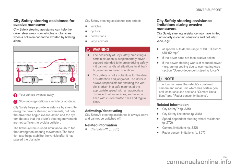
City Safety steering assistance can help thedriver steer away from vehicles or obstacleswhen a collision cannot be avoided by brakingalone.
Your vehicle swerves away
Slow-moving/stationary vehicle or obstacle.
City Safety helps provide assistance by strength-ening the driver's steering movements, but only ifthe driver has begun evasive action and the sys-tem detects that the driver's steering movementsare not sufficient to avoid a collision.
The brake system is used simultaneously to fur-ther strengthen steering movements. The func-tion also helps stabilize the vehicle after it haspassed the obstacle.
City Safety steering assistance can detect:
vehicles
cyclists
pedestrians
large animals
WARNING
The possibility of City Safety predicting acertain situation is supplementary driversupport intended to improve driving safety– it cannot handle all situations in all traf-fic, weather and road conditions.
City Safety is not a substitute for the driv-er's attention and judgment. The driver isalways responsible for ensuring the vehi-cle is driven in a safe manner, at theappropriate speed, with an appropriatedistance to other vehicles, and in accord-ance with current traffic rules and regula-tions.
Activating/deactivating
City Safety's steering assistance is always activeand cannot be switched off.
Related information
City Safety™ (p. 335)
City Safety steering assistancelimitations during evasivemaneuvers
City Safety steering assistance may have limitedfunctionality in certain situations and not inter-vene, e.g.:
at speeds outside the range of 50-100 km/h(30-62 mph)
if the driver does not take evasive action
if the power steering works at reduced power- e.g. during cooling due to overheating (seesection "Speed-dependent steering force").
NOTE
The function uses the vehicle's combinedcamera and radar unit, which has certain gen-eral limitations; see sections "Camera limita-tions" and "Radar sensor limitations".
Related information
City Safety™ (p. 335)
City Safety limitations (p. 346)
Speed-dependent steering wheel resistance(p. 272)
Camera limitations (p. 332)
Radar sensor limitations (p. 327)
Page 373 of 695
DRIVER SUPPORT
371
Lane Keeping Aid limitations
In certain demanding driving conditions, LaneKeeping Aid may not be able to properly assistthe driver. In these situations, it is recommendedthat the function be deactivated.
Examples of such situations include:
road work
winter driving conditions
poor road surfaces
a very sporty driving style
bad weather with reduced visibility
roads with indistinct or no lane markings
sharp edges or lines other than the lane'sside markings
when the power steering works at reducedpower, e.g. during cooling due to overheating(see section “Speed-dependent steeringforce”).
NOTE
The function uses the vehicle's camera unit,which has some general limitations – see thesection "Camera unit limitations".
Related information
Lane Keeping Aid (p. 367)
Speed-dependent steering wheel resistance(p. 272)
Camera limitations (p. 332)
Page 380 of 695
DRIVER SUPPORT
378
Limitations of Run-Off Mitigationwith steering assistance
In certain demanding driving conditions, thefunction may not be able to properly assist thedriver. In these situations, it is recommendedthat it is turned off.
Examples of such situations include:
road work
winter driving conditions
narrow roads
poor road surfaces
a very sporty driving style
bad weather with reduced visibility
roads with indistinct or no lane markings
sharp edges or lines other than the lane'sside markings
when the power steering works at reducedpower, e.g. during cooling due to overheating(see section “Speed-dependent steeringforce”).
NOTE
The function uses the vehicle's combinedcamera and radar unit, which has certain gen-eral limitations; see sections "Camera limita-tions" and "Radar sensor limitations".
Related information
Steering assistance at risk of collision(p. 375)
Speed-dependent steering wheel resistance(p. 272)
Camera limitations (p. 332)
Radar sensor limitations (p. 327)
Steering assistance during collisionrisks from oncoming traffic
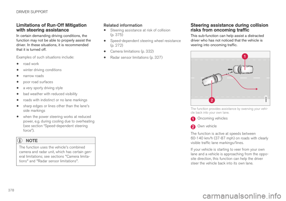
This sub-function can help assist a distracteddriver who has not noticed that the vehicle isveering into oncoming traffic.
The function provides assistance by swerving your vehi-cle back into your own lane.
Oncoming vehicles
Own vehicle
The function is active at speeds between60-140 km/h (37-87 mph) on roads with clearlyvisible traffic lane markings/lines.
If your vehicle is starting to veer from your ownlane and a vehicle is approaching from the oppo-site direction, this function can help the driversteer the vehicle back into its own lane.
Page 415 of 695
HYBRID INFORMATION
}}
413
Gear selector positions for automatic trans-missions (p. 445)
Towing using a towline (p. 483)
Charging the hybrid battery
In addition to the conventional fuel tank, yourvehicle is also equipped with a rechargeablelithium-ion hybrid battery.
WARNING
California Proposition 65
Operating, servicing and maintaining a pas-senger vehicle can expose you to chemicalsincluding engine exhaust, carbon monoxide,phthalates, and lead, which are known to theState of California to cause cancer and birthdefects or other reproductive harm. To mini-mize exposure, avoid breathing exhaust, donot idle the engine except as necessary, serv-ice your vehicle in a well ventilated area andwear gloves or wash your hands frequentlywhen servicing your vehicle. For more infor-mation go to www.P65Warnings.ca.gov/passenger-vehicle.
The hybrid battery can be recharged using thecharging cable stored in a storage space in thecargo compartment.
WARNING
The hybrid electrical system in your vehicleuses high voltage electrical current. Any dam-age to this system or to the hybrid batterymay result in the danger of overheating, fire,or serious injury. If the vehicle is involved in acollision or subjected to flooding, fire, etc.,have it inspected by a trained and qualifiedVolvo service technician. Prior to this inspec-tion, the vehicle should be parked outdoors ata safe distance from any building or poten-tially flammable materials.
The hybrid battery's charging time depends onthe charging current used.
NOTE
The capacity of the hybrid battery diminishessomewhat with age and use, which couldresult in increased use of the gasoline engineand consequently, slightly higher fuel con-sumption.
WARNING
If the hybrid battery needs to be replaced, thismay only be done by a Volvo retailer orauthorized Volvo workshop.
Page 418 of 695
||
HYBRID INFORMATION
416
WARNING
The charging cable must be groundedwhen in use. It is equipped with a cordwith a grounding conductor and agrounding plug. The plug must beinserted into an appropriate outlet that isproperly installed and grounded inaccordance with all local codes and ordi-nances and is not damaged in any way.
Children should be supervised when inthe vicinity of the charging cable when itis plugged in.
High voltage is present in your electricmeter housing and power distributionservice panel. Contact with high voltagecan cause death or serious personalinjury.
Do not use the charging cable if it isdamaged in any way. A damaged or mal-functioning charging cable may only berepaired by a workshop – an authorizedVolvo workshop is recommended.
Always position the charging cable sothat it will not be driven over, stepped on,tripped over or otherwise damaged, orcause personal injury.
Disconnect the charger from the wall out-let before cleaning it.
Never connect the charging cable to anextension cord or a multiple plug socket.
Also, refer to the manufacturer's instructionsfor using the charging cable and its compo-nents.
CAUTION
Power strips, extension cords, surge protec-tors or similar devices must not be usedtogether with the charging cable since thismay involve a risk of fire, electric shocks, etc.
An adapter may not be used between the120/240 V outlet (AC, alternating current)and the charging cable.
CAUTION
Never detach the charging cable from the120/240 V outlet (AC, alternating current)while charging is in progress – the120/240 V outlet could be damaged in suchcircumstances. Always interrupt charging firstand then disconnect the charging cable – firstfrom the vehicle's charging socket and thenfrom the 120/240 V outlet.
CAUTION
Wipe the charging cable with a clean clothlightly moistened with water or a mild deter-gent. Do not use chemicals or solvents.
The charging cable and its components mustnot be rinsed or immersed in water.
CAUTION
Avoid exposing the charging module and itsplug to direct sunlight. In such cases, theoverheating protection in the plug couldreduce or cut off charging of the hybrid bat-tery.
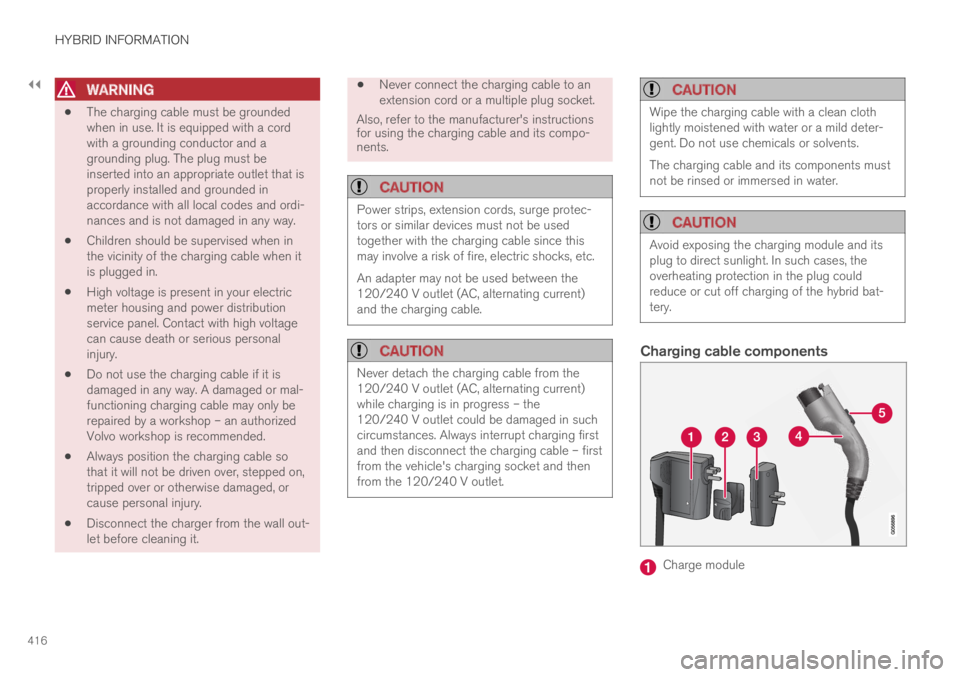
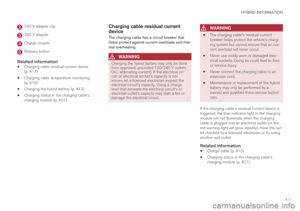
Charging cable components
Charge module
Page 419 of 695
HYBRID INFORMATION
417
240 V adapter clip
240 V adapter
Charge coupler
Release button
Related information
Charging cable residual current device(p. 417)
Charging cable temperature monitoring(p. 418)
Charging the hybrid battery (p. 413)
Charging status in the charging cable'scharging module (p. 421)
Charging cable residual currentdevice
The charging cable has a circuit breaker thathelps protect against current overloads and ther-mal overheating.
WARNING
Charging the hybrid battery may only be donefrom approved, grounded 120/240 V outlets(AC, alternating current). If the electrical cir-cuit or electrical socket's capacity is notknown, let a licensed electrician inspect theelectrical circuit's capacity. Using a chargelevel that exceeds the electrical circuit's orelectrical outlet's capacity may start a fire ordamage the electrical circuit.
WARNING
The charging cable's residual currentbreaker helps protect the vehicle's charg-ing system but cannot ensure that an cur-rent overload will never occur.
Never use visibly worn or damaged elec-trical sockets. Doing so could lead to firesor serious injury.
Never connect the charging cable to anextension cord.
Maintenance or replacement of the hybridbattery may only be performed by atrained and qualified Volvo service techni-cian.
If the charging cable's residual current device istriggered, the blue indicator light in the chargingmodule will not illuminate when the chargingcable is plugged into an electrical outlet (or thered warning light will glow steadily). Have the out-let checked by a licensed electrician or try usinganother wall outlet.
Related information
Charge cable (p. 415)
Charging status in the charging cable'scharging module (p. 421)
Page 432 of 695
STARTING AND DRIVING
* Option/accessory.430
Starting the vehicle
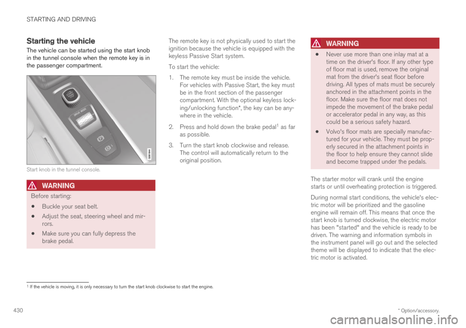
The vehicle can be started using the start knobin the tunnel console when the remote key is inthe passenger compartment.
Start knob in the tunnel console.
WARNING
Before starting:
Buckle your seat belt.
Adjust the seat, steering wheel and mir-rors.
Make sure you can fully depress thebrake pedal.
The remote key is not physically used to start theignition because the vehicle is equipped with thekeyless Passive Start system.
To start the vehicle:
1.The remote key must be inside the vehicle.For vehicles with Passive Start, the key mustbe in the front section of the passengercompartment. With the optional keyless lock-ing/unlocking function*, the key can be any-where in the vehicle.
2. Press and hold down the brake pedal1 as faras possible.
3. Turn the start knob clockwise and release.The control will automatically return to theoriginal position.
WARNING
Never use more than one inlay mat at atime on the driver's floor. If any other typeof floor mat is used, remove the originalmat from the driver's seat floor beforedriving. All types of mats must be securelyanchored in the attachment points in thefloor. Make sure the floor mat does notimpede the movement of the brake pedalor accelerator pedal in any way, as thiscould be a serious safety hazard.
Volvo's floor mats are specially manufac-tured for your vehicle. They must be prop-erly secured in the attachment points inthe floor to help ensure they cannot slideand become trapped under the pedals.
The starter motor will crank until the enginestarts or until overheating protection is triggered.
During normal start conditions, the vehicle's elec-tric motor will be prioritized and the gasolineengine will remain off. This means that once thestart knob is turned clockwise, the electric motorhas been "started" and the vehicle is ready to bedriven. The warning and information symbols inthe instrument panel will go out and the selectedtheme will be displayed to indicate that the elec-tric motor is activated.
1If the vehicle is moving, it is only necessary to turn the start knob clockwise to start the engine.