YAMAHA GRIZZLY 700 2019 Owners Manual
GRIZZLY 700 2019
YAMAHA
YAMAHA
https://www.carmanualsonline.info/img/51/50446/w960_50446-0.png
YAMAHA GRIZZLY 700 2019 Owners Manual
Trending: suspension, low beam, flat tire, ignition, ABS, brake light, brake pads
Page 111 of 180
8-11
8
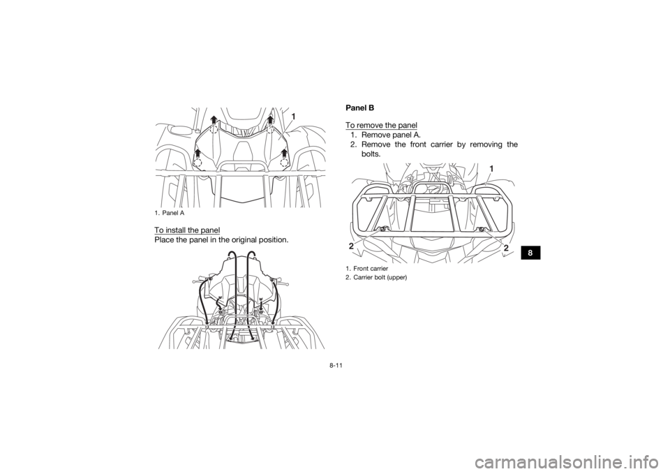
To install the panel
Place the panel in the original position. Panel B
To remove the panel
1. Remove panel A.
2. Remove the front carrier by removing the
bolts.
1. Panel A
1
1. Front carrier
2. Carrier bolt (upper)
1
2
2
UB4F60E0.book Page 11 Wednesday, April 25, 2018 11:52 AM
Page 112 of 180
8-12
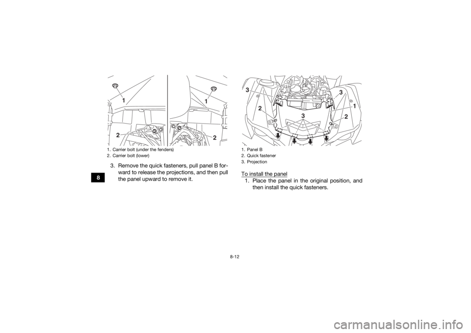
83. Remove the quick fasteners, pull panel B for-
ward to release the projections, and then pull
the panel upward to remove it. To install the panel
1. Place the panel in the original position, and
then install the quick fasteners.
1. Carrier bolt (under the fenders)
2. Carrier bolt (lower)
1
2
2
1
1. Panel B
2. Quick fastener
3. Projection3
3
1
2
3
2
UB4F60E0.book Page 12 Wednesday, April 25, 2018 11:52 AM
Page 113 of 180
8-13
8
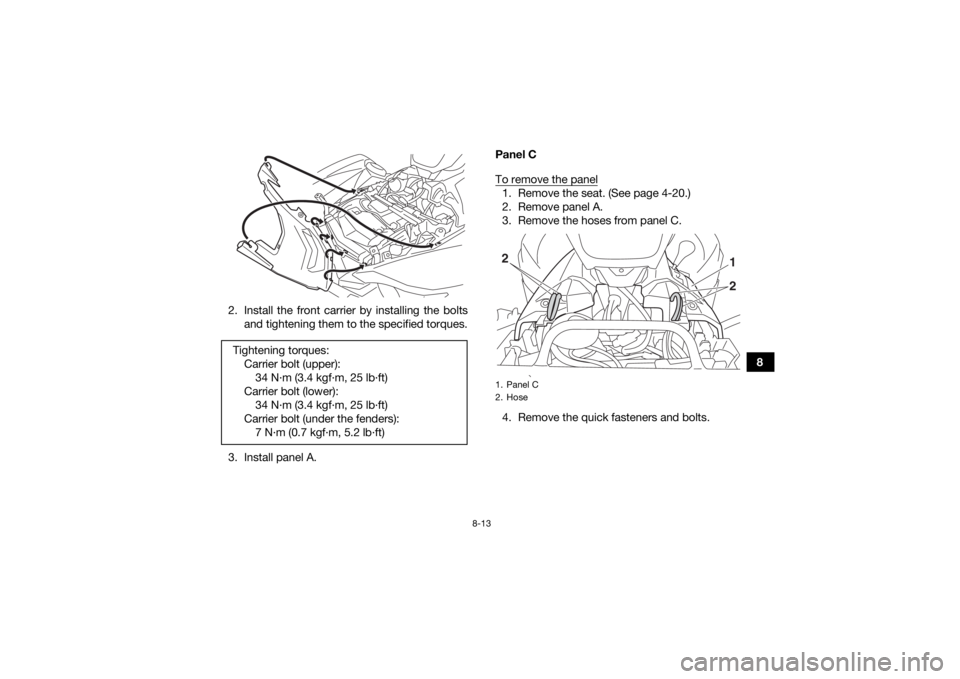
2. Install the front carrier by installing the bolts
and tightening them to the specified torques.
3. Install panel A. Panel C
To remove the panel
1. Remove the seat. (See page 4-20.)
2. Remove panel A.
3. Remove the hoses from panel C.
4. Remove the quick fasteners and bolts.
Tightening torques:
Carrier bolt (upper):34 N·m (3.4 kgf·m, 25 lb·ft)
Carrier bolt (lower): 34 N·m (3.4 kgf·m, 25 lb·ft)
Carrier bolt (under the fenders): 7 N·m (0.7 kgf·m, 5.2 lb·ft)1. Panel C
2. Hose
21
2
UB4F60E0.book Page 13 Wednesday, April 25, 2018 11:52 AM
Page 114 of 180
8-14
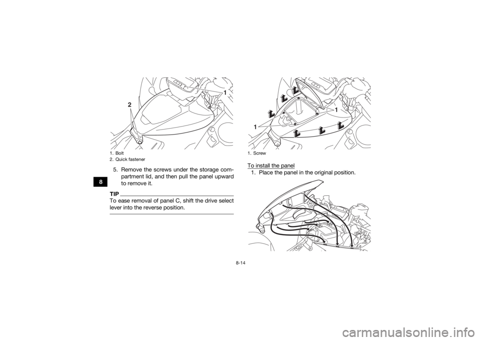
85. Remove the screws under the storage com-
partment lid, and then pull the panel upward
to remove it.
TIPTo ease removal of panel C, shift the drive select
lever into the reverse position.
To install the panel1. Place the panel in the original position.
1. Bolt
2. Quick fastener
1
2
1. Screw
1
1
UB4F60E0.book Page 14 Wednesday, April 25, 2018 11:52 AM
Page 115 of 180
8-15
8
2. Install the screws, quick fasteners, bolts, and
hoses.
TIPMake sure that the hoses are properly connected
and routed, and are not pinched. 3. Install panel A.
4. Install the seat.
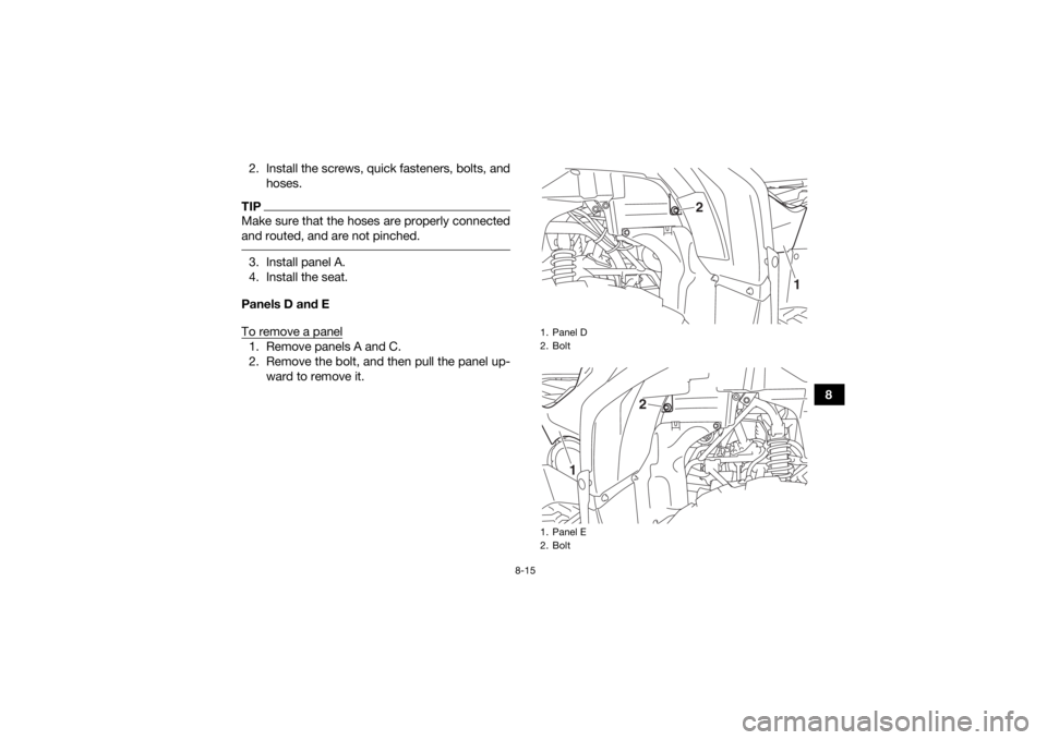
Panels D and E
To remove a panel1. Remove panels A and C.
2. Remove the bolt, and then pull the panel up- ward to remove it.
1. Panel D
2. Bolt
1. Panel E
2. Bolt
1
2
1
2
UB4F60E0.book Page 15 Wednesday, April 25, 2018 11:52 AM
Page 116 of 180
8-16
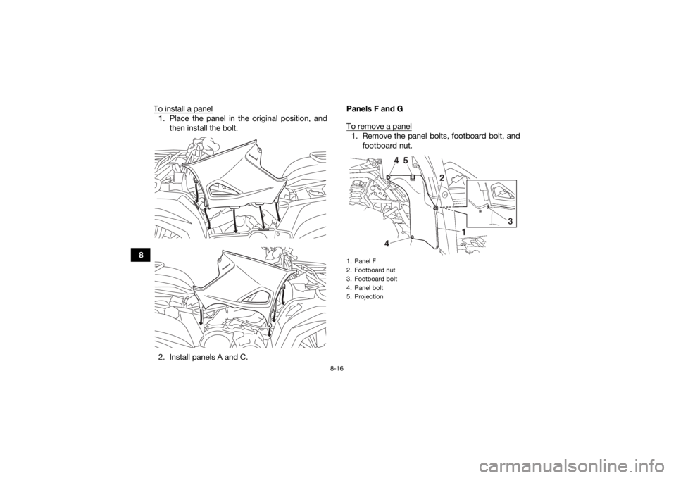
8To install a panel
1. Place the panel in the original position, and
then install the bolt.
2. Install panels A and C. Panels F and G
To remove a panel
1. Remove the panel bolts, footboard bolt, and
footboard nut.1. Panel F
2. Footboard nut
3. Footboard bolt
4. Panel bolt
5. Projection
UB4F60E0.book Page 16 Wednesday, April 25, 2018 11:52 AM
Page 117 of 180
8-17
8
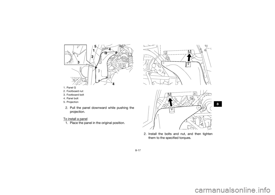
2. Pull the panel downward while pushing the
projection.
To install a panel
1. Place the panel in the original position.
2. Install the bolts and nut, and then tightenthem to the specified torques.1. Panel G
2. Footboard nut
3. Footboard bolt
4. Panel bolt
5. ProjectionUB4F60E0.book Page 17 Wednesday, April 25, 2018 11:52 AM
Page 118 of 180
8-18
8
EBU38130Checking the spark plugThe spark plug is an important engine component,
which is easy to check. Since heat and deposits
will cause any spark plug to slowly erode, the
spark plug should be removed and checked in ac-
cordance with the periodic maintenance and lubri-
cation chart. In addition, the condition of the spark
plug can reveal the condition of the engine.
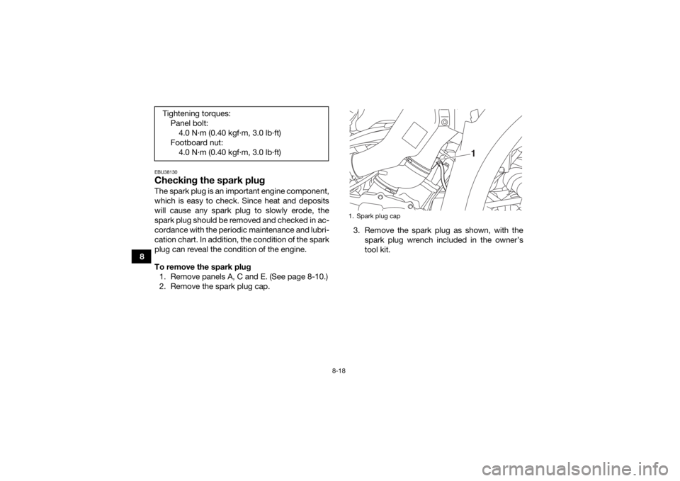
To remove the spark plug1. Remove panels A, C and E. (See page 8-10.)
2. Remove the spark plug cap. 3. Remove the spark plug as shown, with the
spark plug wrench included in the owner’s
tool kit.
Tightening torques:
Panel bolt:4.0 N·m (0.40 kgf·m, 3.0 lb·ft)
Footboard nut: 4.0 N·m (0.40 kgf·m, 3.0 lb·ft)
1. Spark plug cap
1
UB4F60E0.book Page 18 Wednesday, April 25, 2018 11:52 AM
Page 119 of 180
8-19
8
To check the spark plug
1. Check that the porcelain insulator around the center electrode of the spark plug is a medi-
um-to-light tan (the ideal color when the vehi-
cle is ridden normally).
TIPIf the spark plug shows a distinctly different color,
the engine could be operating improperly. Do not
attempt to diagnose such problems yourself. In-
stead, have a Yamaha dealer check the vehicle.
2. Check the spark plug for electrode erosionand excessive carbon or other deposits, and
replace it if necessary.
3. Measure the spark plug gap with a wire thick- ness gauge and, if necessary, adjust the gap
to specification.
1. Spark plug wrench
1
Specified spark plug:NGK/CPR7EA-91. Spark plug gapSpark plug gap:0.8–0.9 mm (0.031–0.035 in)
UB4F60E0.book Page 19 Wednesday, April 25, 2018 11:52 AM
Page 120 of 180
8-20
8To install the spark plug
1. Clean the surface of the spark plug gasket and its mating surface, and then wipe off any
grime from the spark plug threads.
2. Install the spark plug with the spark plug wrench, and then tighten it to the specified
torque.
TIPIf a torque wrench is not available when installing
the spark plug, a good estimate of the correct
torque is 1/4–1/2 turn past finger tight. However,
the spark plug should be tightened to the speci-
fied torque as soon as possible. 3. Install the spark plug cap.
4. Install the panels.
EBU2746CEngine oil and oil filter cartridgeThe engine oil level should be checked before
each ride. In addition, the oil must be changed and
the oil filter cartridge replaced at the intervals
specified in the periodic maintenance and lubrica-
tion chart.
To check the engine oil level1. Park the ATV on a level surface.
2. Check the engine oil level on a cold engine.TIPIf the engine was started before checking the oil
level, warm up the engine, and then wait at least
10 minutes until the oil settles for an accurate
reading. 3. Remove the access cover by turning it coun- terclockwise.
Tightening torque:
Spark plug:13 N·m (1.3 kgf·m, 9.6 lb·ft)
UB4F60E0.book Page 20 Wednesday, April 25, 2018 11:52 AM
Trending: ECU, gas tank size, four wheel drive, final gear, lock, change time, air condition
