fuel YAMAHA SLIDER 50 2014 Owners Manual
[x] Cancel search | Manufacturer: YAMAHA, Model Year: 2014, Model line: SLIDER 50, Model: YAMAHA SLIDER 50 2014Pages: 68, PDF Size: 2.03 MB
Page 6 of 68

TABLE OF CONTENTSSAFETY INFORMATION.................. 1-1
Further safe-riding points ............... 1-5
DESCRIPTION.................................. 2-1
Left view ......................................... 2-1
Right view ....................................... 2-2
Controls and instruments ............... 2-3
INSTRUMENT AND CONTROL
FUNCTIONS...................................... 3-1
Main switch/steering lock............... 3-1
Indicator lights and warning
lights............................................ 3-2
Speedometer unit ........................... 3-3
Handlebar switches ........................ 3-3
Front brake lever ............................ 3-4
Rear brake lever ............................. 3-4
Fuel and 2-stroke engine oil tank
caps ............................................ 3-5
Fuel ................................................. 3-5
Catalytic converter ......................... 3-6
2-stroke engine oil .......................... 3-7
Starter (choke) lever ...................... 3-7
Kickstarter ...................................... 3-8
Seat ................................................ 3-8
Anti-theft device housing ............... 3-8
Luggage hook................................. 3-9FOR YOUR SAFETY –
PRE-OPERATION CHECKS............. 4-1
OPERATION AND IMPORTANT
RIDING POINTS................................ 5-1
Starting a cold engine ..................... 5-1
Starting a warm engine ................... 5-2
Starting off ...................................... 5-2
Acceleration and deceleration ........ 5-3
Braking ............................................ 5-3
Tips for reducing fuel
consumption ................................ 5-4
Engine break-in ............................... 5-4
Parking ............................................ 5-5
PERIODIC MAINTENANCE AND
ADJUSTMENT................................... 6-1
Periodic maintenance chart for the
emission control system .............. 6-2
General maintenance and
lubrication chart ........................... 6-3
Removing and installing the
cowling and panel........................ 6-6
Checking the spark plug ................. 6-7
Final transmission oil....................... 6-8
Cleaning the air filter element ......... 6-9
Adjusting the carburetor ............... 6-10
Checking the throttle grip free
play ............................................ 6-10
Tires .............................................. 6-10
Cast wheels................................... 6-12Checking the front brake lever
free play..................................... 6-13
Adjusting the rear brake lever
free play..................................... 6-13
Checking the front brake pads
and rear brake shoes ............... 6-14
Checking the brake fluid level ...... 6-14
Changing the brake fluid .............. 6-15
Checking and lubricating the
cables ........................................ 6-16
Checking and lubricating the
throttle grip and cable ............... 6-16
Lubricating the front and rear
brake levers ............................... 6-16
Checking and lubricating the
centerstand ............................... 6-17
Checking the front fork ................. 6-18
Checking the steering................... 6-18
Checking the wheel bearings ....... 6-19
Battery .......................................... 6-19
Replacing the fuse ........................ 6-21
Replacing the headlight bulb ........ 6-21
Replacing the tail/brake light
bulb ........................................... 6-22
Replacing a turn signal light
bulb ........................................... 6-22
Troubleshooting............................ 6-23
Troubleshooting chart .................. 6-24
SCOOTER CARE AND STORAGE... 7-1
Matte color caution......................... 7-1U1S0E2E0.book Page 1 Thursday, July 25, 2013 6:53 PM
Page 15 of 68
DESCRIPTION
2-2
2
EAU10421
Right view
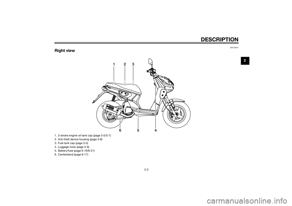
123
4 5 6
1. 2-stroke engine oil tank cap (page 3-5/3-7)
2. Anti-theft device housing (page 3-8)
3. Fuel tank cap (page 3-5)
4. Luggage hook (page 3-9)
5. Battery/fuse (page 6-19/6-21)
6. Centerstand (page 6-17)
U1S0E2E0.book Page 2 Thursday, July 25, 2013 6:53 PM
Page 17 of 68
INSTRUMENT AND CONTROL FUNCTIONS
3-1
3
EAU10462
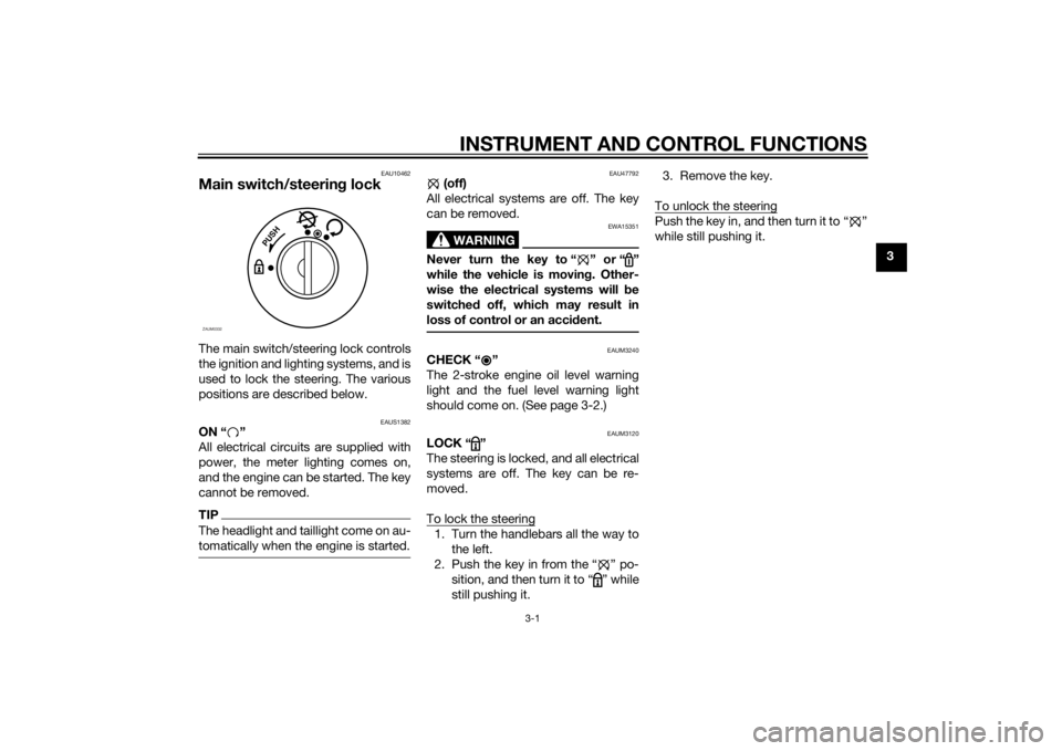
Main switch/steering lockThe main switch/steering lock controls
the ignition and lighting systems, and is
used to lock the steering. The various
positions are described below.
EAUS1382
ON “ ”
All electrical circuits are supplied with
power, the meter lighting comes on,
and the engine can be started. The key
cannot be removed.TIPThe headlight and taillight come on au-
tomatically when the engine is started.
EAU47792
(off)
All electrical systems are off. The key
can be removed.
WARNING
EWA15351
Never turn the key to “ ” or “ ”
while the vehicle is moving. Other-
wise the electrical systems will be
switched off, which may result in
loss of control or an accident.
EAUM3240
CHECK “ ”
The 2-stroke engine oil level warning
light and the fuel level warning light
should come on. (See page 3-2.)
EAUM3120
LOCK “ ”
The steering is locked, and all electrical
systems are off. The key can be re-
moved.
To lock the steering1. Turn the handlebars all the way to
the left.
2. Push the key in from the “ ” po-
sition, and then turn it to “ ” while
still pushing it.3. Remove the key.
To unlock the steering
Push the key in, and then turn it to “ ”
while still pushing it.
P
U
S
H
ZAUM0332
U1S0E2E0.book Page 1 Thursday, July 25, 2013 6:53 PM
Page 18 of 68
INSTRUMENT AND CONTROL FUNCTIONS
3-2
3
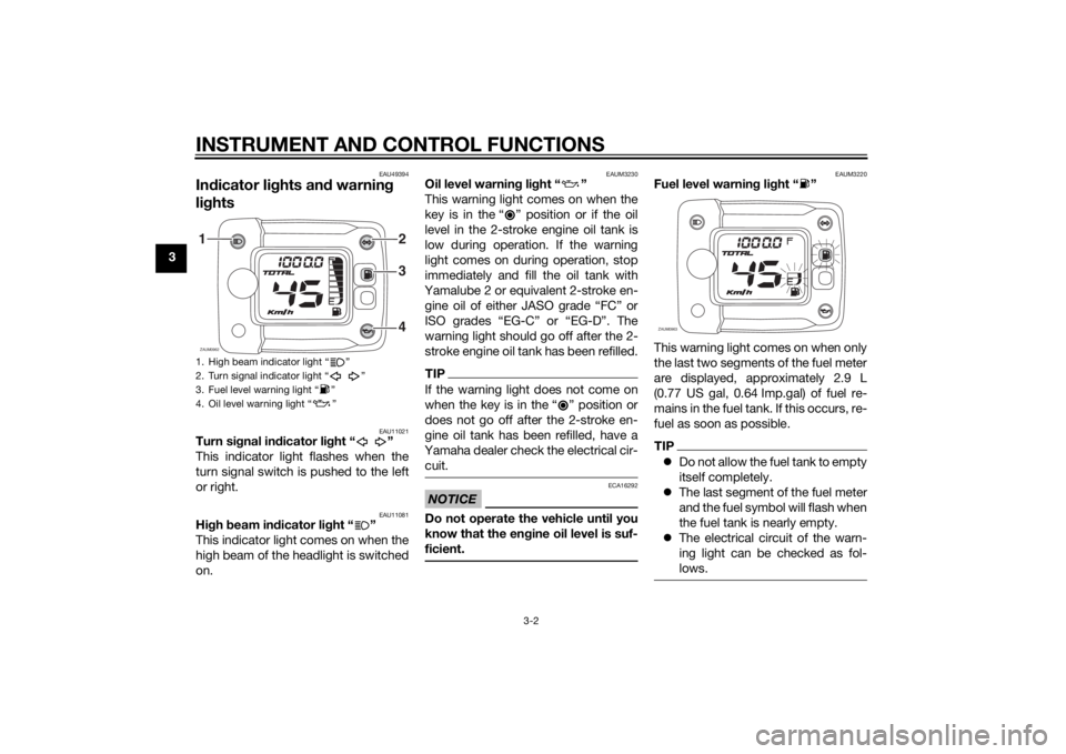
EAU49394
Indicator lights and warning
lights
EAU11021
Turn signal indicator light “ ”
This indicator light flashes when the
turn signal switch is pushed to the left
or right.
EAU11081
High beam indicator light “ ”
This indicator light comes on when the
high beam of the headlight is switched
on.
EAUM3230
Oil level warning light “ ”
This warning light comes on when the
key is in the “ ” position or if the oil
level in the 2-stroke engine oil tank is
low during operation. If the warning
light comes on during operation, stop
immediately and fill the oil tank with
Yamalube 2 or equivalent 2-stroke en-
gine oil of either JASO grade “FC” or
ISO grades “EG-C” or “EG-D”. The
warning light should go off after the 2-
stroke engine oil tank has been refilled.TIPIf the warning light does not come on
when the key is in the Ž position or
does not go off after the 2-stroke en-
gine oil tank has been refilled, have a
Yamaha dealer check the electrical cir-
cuit.NOTICE
ECA16292
Do not operate the vehicle until you
know that the engine oil level is suf-
ficient.
EAUM3220
Fuel level warning light “ ”
This warning light comes on when only
the last two segments of the fuel meter
are displayed, approximately 2.9 L
(0.77 US gal, 0.64 Imp.gal) of fuel re-
mains in the fuel tank. If this occurs, re-
fuel as soon as possible.TIPDo not allow the fuel tank to empty
itself completely.
The last segment of the fuel meter
and the fuel symbol will flash when
the fuel tank is nearly empty.
The electrical circuit of the warn-
ing light can be checked as fol-
lows.
1. High beam indicator light “ ”
2. Turn signal indicator light “ ”
3. Fuel level warning light “ ”
4. Oil level warning light “ ”ZAUM0962
3
42 1
ZAUM0963
U1S0E2E0.book Page 2 Thursday, July 25, 2013 6:53 PM
Page 19 of 68

INSTRUMENT AND CONTROL FUNCTIONS
3-3
3 Turn the key to “ ”. If the warning light
does not come on, have a Yamaha
dealer check the electrical circuit.
EAUM1591
Speedometer unitThe speedometer unit is equipped with
a speedometer, an odometer and a
fuel meter. The speedometer shows
riding speed. The odometer shows the
total distance traveled. The fuel meter
indicates the amount of fuel in the fuel
tank. (See page 3-2 for an explanation
of the fuel level warning light.)
EAU1234F
Handlebar switchesLeft
Right
1. Speedometer
2. Odometer
3. Fuel meter
ZAUM0964
1
23
1. Horn switch Ž
2. Turn signal switch / Ž
3. Dimmer switch / Ž
1. Start switch Ž
12
3
ZAUM0142
1
ZAUM0473
U1S0E2E0.book Page 3 Thursday, July 25, 2013 6:53 PM
Page 21 of 68
INSTRUMENT AND CONTROL FUNCTIONS
3-5
3
EAU13203
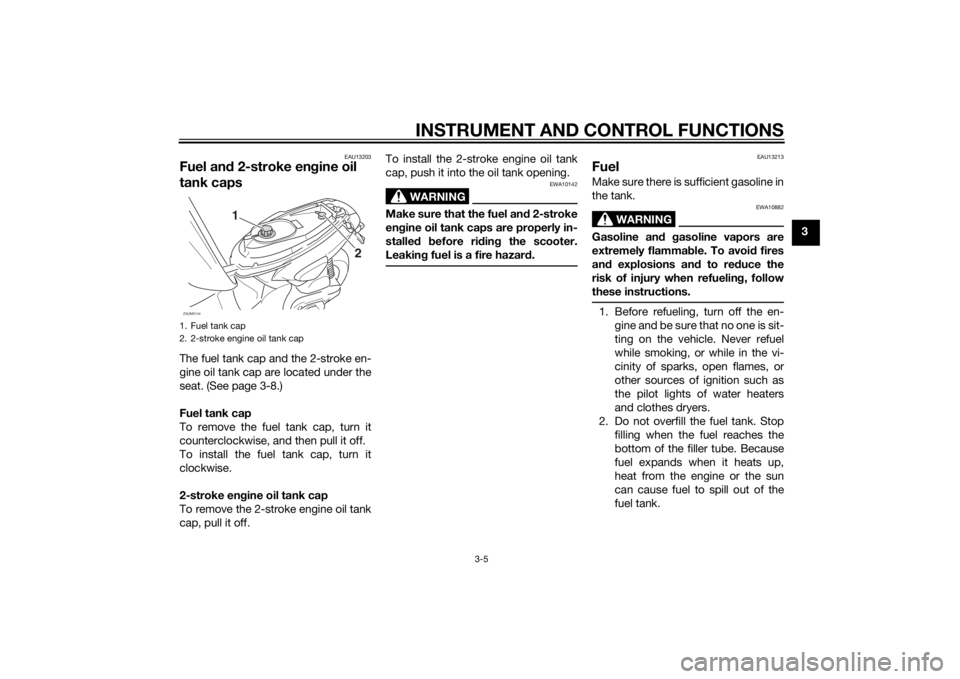
Fuel and 2-stroke engine oil
tank capsThe fuel tank cap and the 2-stroke en-
gine oil tank cap are located under the
seat. (See page 3-8.)
Fuel tank cap
To remove the fuel tank cap, turn it
counterclockwise, and then pull it off.
To install the fuel tank cap, turn it
clockwise.
2-stroke engine oil tank cap
To remove the 2-stroke engine oil tank
cap, pull it off.To install the 2-stroke engine oil tank
cap, push it into the oil tank opening.
WARNING
EWA10142
Make sure that the fuel and 2-stroke
engine oil tank caps are properly in-
stalled before riding the scooter.
Leaking fuel is a fire hazard.
EAU13213
FuelMake sure there is sufficient gasoline in
the tank.
WARNING
EWA10882
Gasoline and gasoline vapors are
extremely flammable. To avoid fires
and explosions and to reduce the
risk of injury when refueling, follow
these instructions.1. Before refueling, turn off the en-
gine and be sure that no one is sit-
ting on the vehicle. Never refuel
while smoking, or while in the vi-
cinity of sparks, open flames, or
other sources of ignition such as
the pilot lights of water heaters
and clothes dryers.
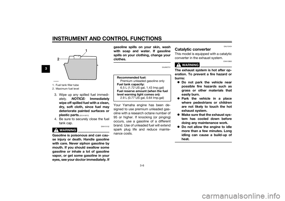
2. Do not overfill the fuel tank. Stop
filling when the fuel reaches the
bottom of the filler tube. Because
fuel expands when it heats up,
heat from the engine or the sun
can cause fuel to spill out of the
fuel tank.
1. Fuel tank cap
2. 2-stroke engine oil tank cap
2 1
ZAUM0144
U1S0E2E0.book Page 5 Thursday, July 25, 2013 6:53 PM
Page 22 of 68
INSTRUMENT AND CONTROL FUNCTIONS
3-6
3
3. Wipe up any spilled fuel immedi-
ately. NOTICE: Immediately
wipe off spilled fuel with a clean,
dry, soft cloth, since fuel may
deteriorate painted surfaces or
plastic parts.
[ECA10072]
4. Be sure to securely close the fuel
tank cap.
WARNING
EWA15152
Gasoline is poisonous and can cau-
se injury or death. Handle gasoline
with care. Never siphon gasoline by
mouth. If you should swallow some
gasoline or inhale a lot of gasoline
vapor, or get some gasoline in your
eyes, see your doctor immediately. Ifgasoline spills on your skin, wash
with soap and water. If gasoline
spills on your clothing, change your
clothes.
EAUM2731
Your Yamaha engine has been de-
signed to use premium unleaded gas-
oline with a research octane number of
95 or higher. If knocking (or pinging)
occurs, use a gasoline of a different
brand. Use of unleaded fuel will extend
spark plug life and reduce mainte-
nance costs.
EAU13434
Catalytic converterThis model is equipped with a catalytic
converter in the exhaust system.
WARNING
EWA10863
The exhaust system is hot after op-
eration. To prevent a fire hazard or
burns:
Do not park the vehicle near
possible fire hazards such as
grass or other materials that
easily burn.
Park the vehicle in a place
where pedestrians or children
are not likely to touch the hot
exhaust system.
Make sure that the exhaust sys-
tem has cooled down before
doing any maintenance work.
Do not allow the engine to idle
more than a few minutes. Long
idling can cause a build-up of
heat.
1. Fuel tank filler tube
2. Maximum fuel level
1
2
ZAUM0020
Recommended fuel:
Premium unleaded gasoline only
Fuel tank capacity:
6.5 L (1.72 US gal, 1.43 Imp.gal)
Fuel reserve amount (when the fuel
level warning light comes on):
2.9 L (0.77 US gal, 0.64 Imp.gal)
U1S0E2E0.book Page 6 Thursday, July 25, 2013 6:53 PM
Page 23 of 68
INSTRUMENT AND CONTROL FUNCTIONS
3-7
3
NOTICE
ECA10702
Use only unleaded gasoline. The use
of leaded gasoline will cause unre-
pairable damage to the catalytic
converter.
EAUM1152
2-stroke engine oilMake sure that there is sufficient oil in
the 2-stroke engine oil tank. Add the
recommended 2-stroke engine oil if
necessary.TIPMake sure that the 2-stroke engine oil
tank cap is properly installed.
EAU13591
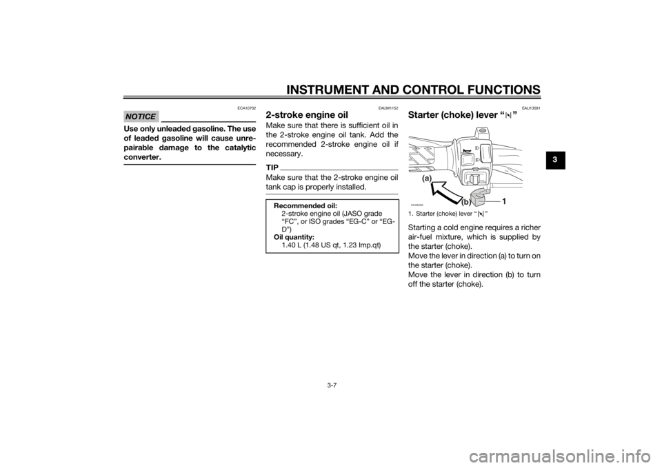
Starter (choke) lever “ ”Starting a cold engine requires a richer
air-fuel mixture, which is supplied by
the starter (choke).
Move the lever in direction (a) to turn on
the starter (choke).
Move the lever in direction (b) to turn
off the starter (choke).
Recommended oil:
2-stroke engine oil (JASO grade
“FC”, or ISO grades “EG-C” or “EG-
D”)
Oil quantity:
1.40 L (1.48 US qt, 1.23 Imp.qt)
1. Starter (choke) lever “ ”
1
(a)
(b)
ZAUM0309
U1S0E2E0.book Page 7 Thursday, July 25, 2013 6:53 PM
Page 26 of 68
FOR YOUR SAFETY – PRE-OPERATION CHECKS
4-1
4
EAU15598
Inspect your vehicle each time you use it to make sure the vehicle is in safe operating condition. Always follow the inspection
and maintenance procedures and schedules described in the Owner’s Manual.
WARNING
EWA11152
Failure to inspect or maintain the vehicle properly increases the possibility of an accident or equipment damage.
Do not operate the vehicle if you find any problem. If a problem cannot be corrected by the procedures provided in
this manual, have the vehicle inspected by a Yamaha dealer.Before using this vehicle, check the following points:
ITEM CHECKS PAGE
Fuel• Check fuel level in fuel tank.
• Refuel if necessary.
• Check fuel line for leakage.3-5
2-stroke engine oil• Check oil level in oil tank.
• If necessary, add recommended oil to specified level.
• Check vehicle for oil leakage.3-7
Final transmission oil• Check vehicle for oil leakage. 6-8
Front brake• Check operation.
• If soft or spongy, have Yamaha dealer bleed hydraulic system.
• Check brake pads for wear.
• Replace if necessary.
• Check fluid level in reservoir.
• If necessary, add specified brake fluid to specified level.
• Check hydraulic system for leakage.6-14, 6-14
Rear brake• Check operation.
• Lubricate cable if necessary.
• Check lever free play.
• Adjust if necessary.6-13, 6-14
U1S0E2E0.book Page 1 Thursday, July 25, 2013 6:53 PM
Page 31 of 68
OPERATION AND IMPORTANT RIDING POINTS
5-4
5
EAU16821
Tips for reducing fuel con-
sumptionFuel consumption depends largely on
your riding style. Consider the follow-
ing tips to reduce fuel consumption:
Avoid high engine speeds during
acceleration.
Avoid high engine speeds with no
load on the engine.
Turn the engine off instead of let-
ting it idle for an extended length
of time (e.g., in traffic jams, at traf-
fic lights or at railroad crossings).
EAU16831
Engine break-inThere is never a more important period
in the life of your engine than the period
between 0 and 1000 km (600 mi). For
this reason, you should read the fol-
lowing material carefully.
Since the engine is brand new, do not
put an excessive load on it for the first
1000 km (600 mi). The various parts in
the engine wear and polish themselves
to the correct operating clearances.
During this period, prolonged full-throt-
tle operation or any condition that
might result in engine overheating
must be avoided.
EAUM2092
0–150 km (0–90 mi)
Avoid prolonged operation above 1/3
throttle. Vary the speed of the scooter
from time to time. Do not operate it at
one set throttle position.
150–500 km (90–300 mi)
Avoid prolonged operation above 1/2
throttle.
500–1000 km (300–600 mi)
Avoid cruising speeds in excess of 3/4
throttle.1000 km (600 mi) and beyond
Avoid prolonged full throttle operation.
Vary speeds occasionally. NOTICE:
After 1000 km (600 mi) of operation,
the final transmission oil must be
changed.
[ECAM1072]
NOTICE
ECA10271
If any engine trouble should occur
during the engine break-in period,
immediately have a Yamaha dealer
check the vehicle.
U1S0E2E0.book Page 4 Thursday, July 25, 2013 6:53 PM