steering YAMAHA SUPERJET 2010 Owners Manual
[x] Cancel search | Manufacturer: YAMAHA, Model Year: 2010, Model line: SUPERJET, Model: YAMAHA SUPERJET 2010Pages: 78, PDF Size: 4.6 MB
Page 6 of 78

Table of contents
General and important labels ........... 1
Identification numbers .................... 1
Primary Identification (PRI-ID)
number ........................................... 1
Craft Identification Number (CIN) ...... 1
Engine serial number ........................ 1
Important labels .............................. 2
Warning labels ................................... 3
Other labels ....................................... 6
Safety information ............................. 7
Limitations on who may operate
the watercraft .............................. 7
Cruising limitations ......................... 8
Operation requirements ................. 9
Recommended equipment ........... 11
Hazard information ....................... 12
Watercraft characteristics ............. 12
Safe boating rules ........................ 13
Enjoy your watercraft
responsibly ................................ 14
Description....................................... 15
Watercraft glossary ...................... 15
Location of main components ...... 16
Control function operation ............. 18
Watercraft control functions ......... 18
Engine stop switch .......................... 18
Engine shut-off switch ..................... 18
Start switch ...................................... 18
Throttle lever ................................... 19
Steering system ............................... 19
Steering pole ................................... 19
Fuel cock knob ................................ 19
Choke knob ..................................... 20
Cooling water pilot outlet ................. 20
Water separator ............................... 21
Engine overheat warning system .... 21
Equipment operation ...................... 22
Equipment .................................... 22
Hood ................................................ 22Bow rope hole ................................. 23
Stern rope hole ................................ 23
Storage pouch ................................. 23
Fire extinguisher container .............. 24
Operation and handling
requirements ................................... 26
Fuel and engine oil
requirements ............................. 26
Fuel ................................................. 26
2-stroke engine oil ........................... 26
Mixing fuel and oil ............................ 26
Filling the fuel tank .......................... 27
Draining the bilge water ............... 28
Draining the bilge water on water .... 28
Transporting ................................. 28
First-time operation ........................ 30
Engine break-in ............................ 30
Pre-operation checks ..................... 31
Pre-operation checklist .................... 31
Pre-operation check points .......... 33
Pre-launch checks ........................... 33
Post-launch checks ......................... 37
Operation ......................................... 39
Operating your watercraft ............ 39
Getting to know your watercraft ....... 39
Learning to operate your
watercraft ..................................... 39
Operating positions ......................... 39
Launching the watercraft ................. 40
Starting the engine on water ........... 40
Stopping the engine ........................ 42
Leaving the watercraft ..................... 42
Operating the watercraft .................. 42
Turning the watercraft ..................... 42
Stopping the watercraft ................... 44
Starting off ....................................... 44
Capsized watercraft ......................... 47
Beaching the watercraft ................... 48
Operating in weeded areas ............. 48
UF2F72E0.book Page 1 Friday, May 22, 2009 5:11 PM
Page 7 of 78
Table of contents
After removing the watercraft from
the water ...................................... 48
Care and storage ............................. 49
Post-operation care ...................... 49
Flushing the cooling water
passages ...................................... 49
Cleaning the watercraft ................... 50
Battery care ..................................... 50
Long-term storage ........................ 53
Cleaning .......................................... 53
Lubrication ....................................... 53
Rustproofing .................................... 54
Maintenance..................................... 55
Maintenance ................................. 55
Tool kit ............................................. 55
Adjusting the steering friction .......... 55
Adjusting the jet thrust nozzle
angle ............................................ 56
Periodic maintenance chart ............. 58
Lubrication points ............................ 59
Checking the fuel filter ..................... 59
Checking the spark plugs ................ 59
Adjusting the choke cable ............... 60
Adjusting the carburetor .................. 61
Specifications .................................. 62
Specifications ................................ 62
Trouble recovery ............................. 63
Troubleshooting ........................... 63
Troubleshooting chart ...................... 63
Emergency procedures ................ 65
Cleaning the jet intake and
impeller ........................................ 65
Jumping the battery ......................... 66
Replacing the fuse ........................... 66
Towing the watercraft ...................... 67
Submerged watercraft ..................... 67
UF2F72E0.book Page 2 Friday, May 22, 2009 5:11 PM
Page 23 of 78
Description
16
EJU31011
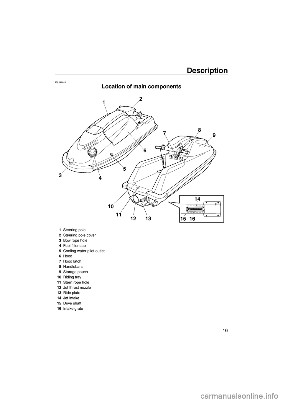
Location of main components
2
1
3
45678
9
10
11
12 13
15 16
1Steering pole
2Steering pole cover
3Bow rope hole
4Fuel filler cap
5Cooling water pilot outlet
6Hood
7Hood latch
8Handlebars
9Storage pouch
10Riding tray
11Stern rope hole
12Jet thrust nozzle
13Ride plate
14Jet intake
15Drive shaft
16Intake grate
UF2F72E0.book Page 16 Friday, May 22, 2009 5:11 PM
Page 26 of 78
![YAMAHA SUPERJET 2010 Owners Manual Control function operation
19
will not start. Also, the starter motor could
be damaged.
[ECJ01040]
The engine will not start when the clip is re-
moved from the engine shut-off switch.
EJU31211Thrott YAMAHA SUPERJET 2010 Owners Manual Control function operation
19
will not start. Also, the starter motor could
be damaged.
[ECJ01040]
The engine will not start when the clip is re-
moved from the engine shut-off switch.
EJU31211Thrott](/img/51/51304/w960_51304-25.png)
Control function operation
19
will not start. Also, the starter motor could
be damaged.
[ECJ01040]
The engine will not start when the clip is re-
moved from the engine shut-off switch.
EJU31211Throttle lever
The throttle lever increases the engine speed
when the lever is squeezed.
The throttle lever returns automatically to its
fully closed (idle) position when released.
EJU35931Steering system
By turning the handlebars in the direction you
wish to travel, the angle of the jet thrust nozzleis changed, and the direction of the watercraft
is changed accordingly.
Since the strength of the jet thrust determines
the speed and degree of a turn, throttle must
always be applied when attempting a turn, ex-
cept at trolling speed.
The angle of the jet thrust nozzle can be ad-
justed to suit operator preference. (See page
56 for adjustment procedures.)
EJU31272Steering pole
The steering pole can be moved up or down
to change the height of the handlebars.
EJU31123Fuel cock knob
The fuel supply method can be switched by
operating the fuel cock knob.
1Start switch
1Throttle lever1Handlebar
2Jet thrust nozzle
UF2F72E0.book Page 19 Friday, May 22, 2009 5:11 PM
Page 29 of 78
Equipment operation
22
EJU40332
Equipment EJU31056Hood
The hood is removable.
Remove the hood to access the engine com-
partment.
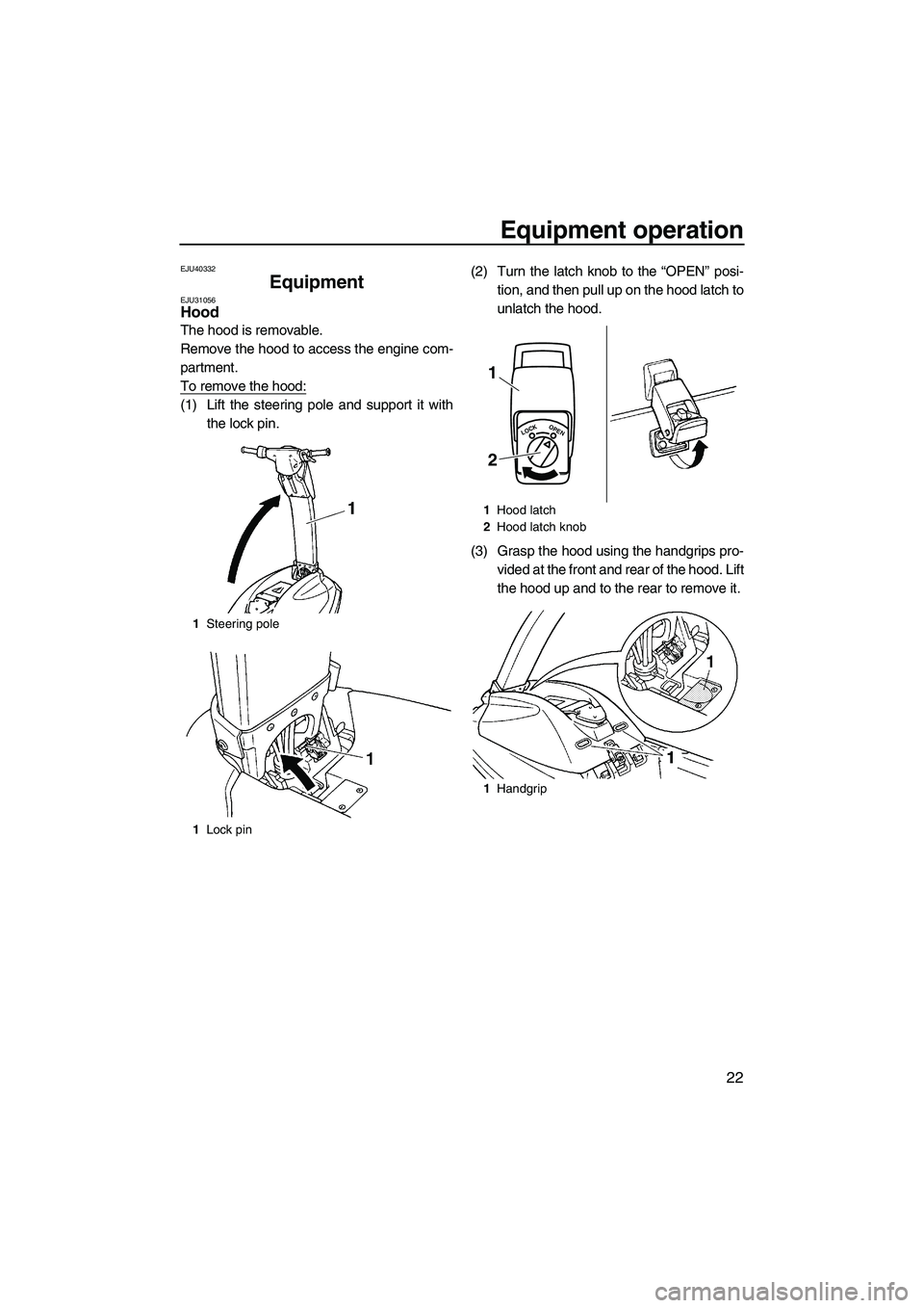
To remove the hood:
(1) Lift the steering pole and support it with
the lock pin.(2) Turn the latch knob to the “OPEN” posi-
tion, and then pull up on the hood latch to
unlatch the hood.
(3) Grasp the hood using the handgrips pro-
vided at the front and rear of the hood. Lift
the hood up and to the rear to remove it.
1Steering pole
1Lock pin
1Hood latch
2Hood latch knob
1Handgrip
LOCKOPEN
1
2
UF2F72E0.book Page 22 Friday, May 22, 2009 5:11 PM
Page 30 of 78

Equipment operation
23
To install the hood:
(1) Position the hood on the deck so that the
two projections at the front of the hood fit
under the two stays on the deck.
(2) Push down on the hood latch, and then
turn the knob to the “LOCK” position to
securely lock the hood in place.
(3) While holding the steering pole, move the
lock pin to the stowed position, and then
lower the steering pole.
EJU36001Bow rope hole
The bow rope hole is used to attach a rope to
the watercraft when transporting, mooring, ortowing it in an emergency. (See page 67 for
towing procedures.)
EJU36011Stern rope hole
The stern rope hole is used to attach a rope to
the watercraft when mooring it.
EJU31674Storage pouch
The storage pouch is located on the bottom of
the hood.
Use the storage pouch to store the own-
er’s/operator’s manual, tool kit, and other
small items. The storage pouch is not de-
signed to be waterproof. If you carry objects
that must be kept dry, put them in a water-
proof bag.
To remove the storage pouch:
(1) Remove the hood. (See page 22 for hood
removal and installation procedures.)
LOCKOPEN
1Bow rope hole
1Stern rope hole
UF2F72E0.book Page 23 Friday, May 22, 2009 5:11 PM
Page 31 of 78
Equipment operation
24
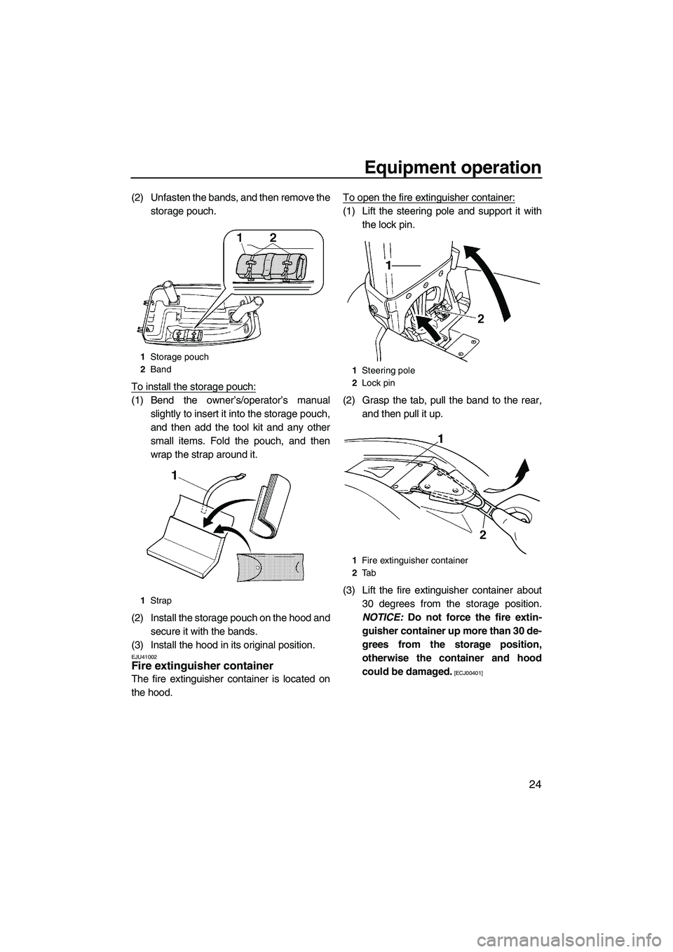
(2) Unfasten the bands, and then remove the
storage pouch.
To install the storage pouch:
(1) Bend the owner’s/operator’s manual
slightly to insert it into the storage pouch,
and then add the tool kit and any other
small items. Fold the pouch, and then
wrap the strap around it.
(2) Install the storage pouch on the hood and
secure it with the bands.
(3) Install the hood in its original position.
EJU41002Fire extinguisher container
The fire extinguisher container is located on
the hood.To open the fire extinguisher container:
(1) Lift the steering pole and support it with
the lock pin.
(2) Grasp the tab, pull the band to the rear,
and then pull it up.
(3) Lift the fire extinguisher container about
30 degrees from the storage position.
NOTICE: Do not force the fire extin-
guisher container up more than 30 de-
grees from the storage position,
otherwise the container and hood
could be damaged.
[ECJ00401]
1Storage pouch
2Band
1Strap
1Steering pole
2Lock pin
1Fire extinguisher container
2Ta b
UF2F72E0.book Page 24 Friday, May 22, 2009 5:11 PM
Page 32 of 78
Equipment operation
25
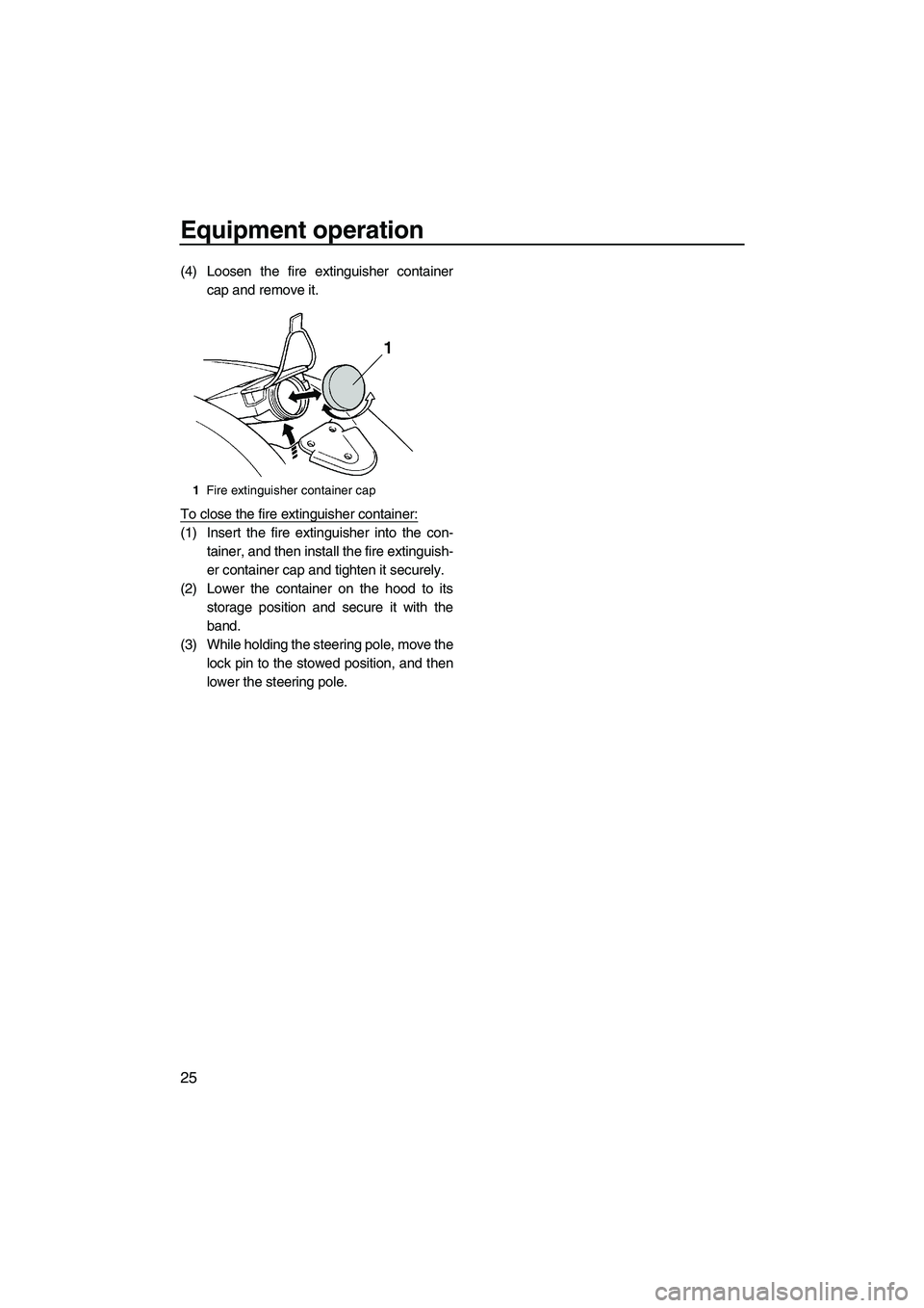
(4) Loosen the fire extinguisher container
cap and remove it.
To close the fire extinguisher container:
(1) Insert the fire extinguisher into the con-
tainer, and then install the fire extinguish-
er container cap and tighten it securely.
(2) Lower the container on the hood to its
storage position and secure it with the
band.
(3) While holding the steering pole, move the
lock pin to the stowed position, and then
lower the steering pole.
1Fire extinguisher container cap
UF2F72E0.book Page 25 Friday, May 22, 2009 5:11 PM
Page 35 of 78
Operation and handling requirements
28
EJU40021
Draining the bilge water
NOTICE
ECJ01301
Do not run the engine at full throttle when
bilge water remains in the engine compart-
ment. The bilge water can splash into the
engine, which can result in severe dam-
age.
EJU40920Draining the bilge water on water
A small quantity of bilge water will remain in
the engine compartment even after the bilge
water is drained on water. To completely re-
move the bilge water, remove the watercraft
from the water and wipe up any remaining
moisture in the engine compartment with a
dry cloth.
Jet vacuum bilge draining system
While the watercraft is operating, a vacuum is
generated in the jet pump that draws in the
bilge water from the engine compartment and
discharges it from the jet thrust nozzle.
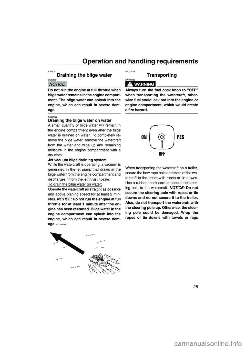
To drain the bilge water on water:
Operate the watercraft as straight as possible
and above planing speed for at least 2 min-
utes. NOTICE: Do not run the engine at full
throttle for at least 1 minute after the en-
gine has been restarted. Bilge water in the
engine compartment can splash into the
engine, which can result in severe dam-
age.
[ECJ00553]EJU33423
Transporting
WARNING
EWJ00750
Always turn the fuel cock knob to “OFF”
when transporting the watercraft, other-
wise fuel could leak out into the engine or
engine compartment, which would create
a fire hazard.
When transporting the watercraft on a trailer,
secure the bow rope hole and stern of the wa-
tercraft to the trailer with ropes or tie downs.
Use a rubber shock cord to secure the steer-
ing pole to the watercraft. NOTICE: Do not
secure the steering pole with ropes or tie
downs and do not secure it to the trailer.
Also, do not transport the watercraft with
the steering pole up. Otherwise, the steer-
ing pole could be damaged. Wrap the
ropes or tie downs with towels or rags
UF2F72E0.book Page 28 Friday, May 22, 2009 5:11 PM
Page 38 of 78
Pre-operation checks
31
EJU31981
WARNING
EWJ00411
Failure to inspect or maintain the watercraft properly increases the possibility of an ac-
cident or damage to the watercraft. Do not operate the watercraft if you find any prob-
lem. If a problem cannot be corrected by the procedures provided in this manual, have
the watercraft inspected by a Yamaha dealer.
EJU31995Pre-operation checklist
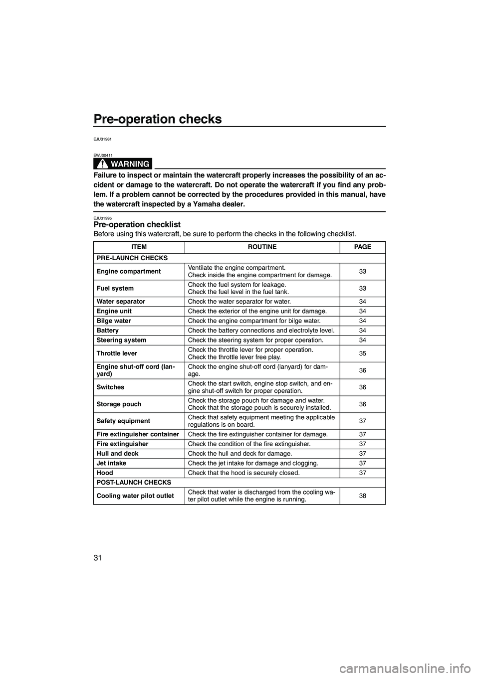
Before using this watercraft, be sure to perform the checks in the following checklist.
ITEM ROUTINE PAGE
PRE-LAUNCH CHECKS
Engine compartmentVentilate the engine compartment.
Check inside the engine compartment for damage.33
Fuel systemCheck the fuel system for leakage.
Check the fuel level in the fuel tank.33
Water separatorCheck the water separator for water. 34
Engine unitCheck the exterior of the engine unit for damage. 34
Bilge waterCheck the engine compartment for bilge water. 34
BatteryCheck the battery connections and electrolyte level. 34
Steering systemCheck the steering system for proper operation. 34
Throttle leverCheck the throttle lever for proper operation.
Check the throttle lever free play.35
Engine shut-off cord (lan-
yard)Check the engine shut-off cord (lanyard) for dam-
age.36
SwitchesCheck the start switch, engine stop switch, and en-
gine shut-off switch for proper operation.36
Storage pouchCheck the storage pouch for damage and water.
Check that the storage pouch is securely installed.36
Safety equipmentCheck that safety equipment meeting the applicable
regulations is on board.37
Fire extinguisher containerCheck the fire extinguisher container for damage. 37
Fire extinguisherCheck the condition of the fire extinguisher. 37
Hull and deckCheck the hull and deck for damage. 37
Jet intakeCheck the jet intake for damage and clogging. 37
HoodCheck that the hood is securely closed. 37
POST-LAUNCH CHECKS
Cooling water pilot outletCheck that water is discharged from the cooling wa-
ter pilot outlet while the engine is running.38
UF2F72E0.book Page 31 Friday, May 22, 2009 5:11 PM