cruise control YAMAHA TMAX 2021 Owners Manual
[x] Cancel search | Manufacturer: YAMAHA, Model Year: 2021, Model line: TMAX, Model: YAMAHA TMAX 2021Pages: 124, PDF Size: 7.93 MB
Page 8 of 124

Table of contentsSafety information ............................ 1-1
Further safe-riding points ............... 1-5
Description ....................................... 2-1
Left view ......................................... 2-1
Right view ....................................... 2-2
Controls and instruments ............... 2-3
Smart key system ........................... 3-1
Smart key system ........................... 3-1
Operating range of the smart key system......................................... 3-2
Handling of the smart key and mechanical key ........................... 3-3
Smart key ....................................... 3-5
Replacing the smart key battery..... 3-6
Powering on the vehicle ................. 3-7
Powering off the vehicle ................. 3-8
How to lock the steering ................ 3-9
How to lock the centerstand ........ 3-10
Storage compartment and fuel tank access ............................... 3-11
Parking mode ............................... 3-13
Special features ............................... 4-1
Cruise control system..................... 4-1
D-mode (drive mode)...................... 4-3
Traction control system .................. 4-4
Instrument an d control functions ... 5-1
Handlebar switches ........................ 5-1 Indicator lights and warning
lights ............................................ 5-2
Speedometer .................................. 5-4
Tachometer ..................................... 5-5
Multi-function display...................... 5-5
Front brake lever ........................... 5-17
Rear brake lever ............................ 5-18
Rear brake lock lever .................... 5-18
Anti-lock brake system (ABS) ....... 5-19
Fuel tank cap ................................ 5-20
Fuel ............................................... 5-20
Fuel tank overflow hose ................ 5-22
Catalytic converter ........................ 5-22
Storage compartments ................. 5-23
Rear view mirrors .......................... 5-24
Shock absorber assembly ............ 5-25
Auxiliary DC jack ........................... 5-26
Sidestand ...................................... 5-27
Ignition circuit cut-off system ....... 5-28
For your safety β pre-operation
checks ............................................... 6-1
Operation an d important ri din g
points ................................................. 7-1
Engine break-in ............................... 7-1
Starting the engine .......................... 7-2
Starting off ...................................... 7-3
Acceleration and deceleration ........ 7-3
Braking ............................................ 7-3 Tips for reducing fuel
consumption ............................... 7-4
Parking............................................ 7-4
Perio dic maintenance an d
a d justment ........................................ 8-1
Tool kit ............................................ 8-2
Periodic maintenance charts .......... 8-3
Periodic maintenance chart for the emission control system ............. 8-3
General maintenance and
lubrication chart .......................... 8-5
Removing and installing panels ...... 8-9
Checking the spark plugs ............. 8-11
Canister ........................................ 8-12
Engine oil and oil filter cartridge ... 8-12
Why Yamalube.............................. 8-15
Coolant ......................................... 8-15
Replacing the engine air filter element and cleaning the
check hose ................................ 8-17
V-belt air filter elements ................ 8-18
Checking the engine idling speed ........................................ 8-18
Checking the throttle grip free play ............................................ 8-19
Valve clearance............................. 8-19
Tires .............................................. 8-19
Cast wheels .................................. 8-21
Checking the front and rear brake lever free play .................. 8-22UB3TE1E0.book Page 1 Friday, September 11, 2020 8:48 AM
Page 32 of 124

Special features
4-1
4
EAU77264
Cruise control systemThe cruise control system is designed
to maintain a set cruising speed be-
tween about 50 km/h (31 mi/h) and 140
km/h (87 mi/h).
WARNING
EWA20950
ο¬Improper use of the cruise con-
trol system may result in loss of
control, which coul d lea d to an
acci dent. Do not activate the
cruise control system in heavy
traffic, poor weather con ditions,
or amon g win din g, slippery,
hilly, rou gh or gravel roa ds.
ο¬ When travelin g uphill or d own-
hill, the cruise control system
may not be ab le to maintain the
set cruisin g speed .
ο¬ To prevent acci dentally activat-
in g the cruise control system,
turn it off when not in use. Make
sure that the cruise control sys-
tem ind icator light β β is off.
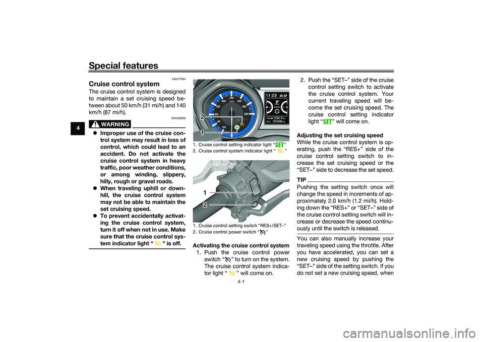
Activating the cruise control system
1. Push the cruise control power switch β β to turn on the system.
The cruise control system indica-
tor light β β will come on. 2. Push the βSETββ side of the cruise
control setting switch to activate
the cruise control system. Your
current traveling speed will be-
come the set cruising speed. The
cruise control setting indicator
light β β will come on.
A djustin g the set cruisin g speed
While the cruise control system is op-
erating, push the βRES+β side of the
cruise control setting switch to in-
crease the set cruising speed or the
βSETββ side to decrease the set speed.
TIPPushing the setting switch once will
change the speed in increments of ap-
proximately 2.0 km/h (1.2 mi/h). Hold-
the cruise control setting switch will in-
crease or decrease the speed continu-
ously until the switch is released.You can also manually increase your
traveling speed using the throttle. After
you have accelerated, you can set a
new cruising speed by pushing the
do not set a new cruising speed, when
1. Cruise control setting indicator light Ε½
2. Cruise control system indicator light Ε½
1.
2. Cruise control power switch Ε½
1 2
1 212
UB3TE1E0.book Page 1 Friday, September 11, 2020 8:48 AM
Page 33 of 124

Special features
4-2
4
you return the throttle grip, the vehicle
will decelerate to the previously set
cruising speed.
Deactivatin
g the cruise control sys-
tem
Perform one of the following opera-
tions to cancel the set cruising speed.
The β β indicator light will turn off. ο¬ Turn the throttle grip past the
closed position in the deceleration
direction.
ο¬ Apply the front or rear brake.
TIPTraveling speed decreases as soon as
the cruise control system is deactivat-
ed; unless the throttle grip is turned.
Usin g the resume function
Push the βRES+β side of the cruise
control setting switch to reactivate the
cruise control system. The traveling
speed will return to the previously set
cruising speed. The β β indicator
light will come on.
WARNING
EWA16351
It is d angerous to use the resume
function when the previously set
cruisin g speed is too hi gh for current
con ditions.Turnin g off the cruise control sys-
tem
Push the cruise control power
switch β β to turn off the cruise con-
trol system. The β β indicator light
and the β β indicator light will turn
off.TIPWhenever the cruise control system or
the vehicle power is turned off, the pre-
viously set cruising speed is erased.
You will not be able to use the resume
function until a new cruising speed has
been set.
Automatic deactivation of the cruisecontrol systemThe cruise control system is electroni-
cally controlled and linked with other
control systems. The cruise control
system will automatically deactivate
under the following conditions: ο¬ The cruise control system is not
able to maintain the set cruising
speed (such as when going up a
steep hill).
ο¬ Wheel slip or wheel spin is detect-
ed. (If the traction control system
is on, traction control will engage.)
ο¬ Engine trouble, etc.
If the cruise control system is automat-
ically deactivated, the β β indicator
light will turn off and the β β indica-
tor light will flash for 4 seconds.
If the cruise control system was auto-
matically deactivated, please stop and
confirm that your vehicle is in good op-
erating condition before continuing on.
When traveling on roads with steep
grades, the cruise control system may
not be able to maintain the set cruising
speed.
1. Deceleration direction
1
UB3TE1E0.book Page 2 Friday, September 11, 2020 8:48 AM
Page 34 of 124

Special features
4-3
4ο¬
When going uphill, the actual trav-
eling speed may become lower
than the set cruising speed. If this
occurs, accelerate to the desired
traveling speed using the throttle.
ο¬ When going downhill, the actual
traveling speed may become
higher than the set cruising speed.
If this occurs, the setting switch
cannot be used to adjust the set
cruising speed. To reduce the
traveling speed, apply the brakes.
When the brakes are applied, the
cruise control system will deacti-
vate.
EAU81392
D-mo de ( drive mo de)D-mode is an electronically controlled
engine performance system with two
mode selections (touring mode βTβ and
sports mode βSβ).
WARNING
EWA18440
Do not chan ge the d rive mo de while
the vehicle is movin g.With the throttle grip closed, push the
drive mode switch βMODEβ to switch
between modes βSβ (sports) and βTβ
(touring).
TIPο¬ The current drive mode is shown
in the drive mode display (page
5-7).
ο¬ The current drive mode is saved
when the vehicle is turned off.
ο¬ D-mode cannot be changed while
cruise control is activated.Tourin g mo de βTβ
The touring mode βTβ is suitable for
various riding conditions.
This mode allows the rider to enjoy
smooth drivability from the low-speed
range to the high-speed range.
Sports mo de βSβ
This mode offers a sportier engine re-
sponse in the low- to mid-speed range
compared to the touring mode.
1. Drive mode switch βMODEβ
1
UB3TE1E0.book Page 3 Friday, September 11, 2020 8:48 AM
Page 36 of 124

Instrument and control functions
5-1
5
EAU77490
Han dle bar switchesLeft Ri
ght
EAU54203
Dimmer/Pass switch β / /PASSβ
Set this switch to β β for the high
beam and to β β for the low beam.
To flash the high beam, push the
switch down towards βPASSβ while the
headlights are on low beam.
EAU66040
Turn si gnal switch β / β
To signal a right-hand turn, push this
switch to β β. To signal a left-hand
turn, push this switch to β β. When
released, the switch returns to the cen-
ter position. To cancel the turn signal
lights, push the switch in after it has re-
turned to the center position.
EAU66030
Horn switch β β
Press this switch to sound the horn.
1. Select switch β / β
2. Menu switch βMENUβ
3. Dimmer/Pass switch β / /PASSβ
4. Cruise control setting switch βRES+/SETββ
5. Turn signal switch β / β
6. Horn switch β β
7. Cruise control power switch β β
1
2
3
4
5
6
7
1. Engine stop switch / Ε½
2.
3. Hazard switch Ε½
4. Ε½
1
2
3
4
UB3TE1E0.book Page 1 Friday, September 11, 2020 8:48 AM
Page 37 of 124

Instrument and control functions
5-2
5
EAU77450
En gine stop switch β / β
Set this switch to β β before starting
the engine. Set this switch to β β to
stop the engine in case of an emergen-
cy, such as when the vehicle overturns
or when the throttle cable is stuck.
EAU77291
Power on/Starter switch βON/ β
With the smart key turned on and with-
in range, press this switch to turn on
the power to the vehicle. Then with the
sidestand up and while applying the
front or rear brake, push this switch to
crank the engine with the starter. See
page 7-2 for starting instructions prior
to starting the engine.
EAU79601
Hazar d switch β β
With the vehicle power is on or in park-
ing mode, use this switch to turn on the
hazard lights (simultaneous flashing of
all turn signal lights).
The hazard lights are used in case of an
emergency or to warn other drivers
when your vehicle is stopped where it
might be a traffic hazard.
NOTICE
ECA10062
Do not use the hazar d lig hts for an
exten ded len gth of time with the en-
g ine not runnin g, otherwise the bat-
tery may d ischarge.
EAU73952
Cruise control switches
See page 4-1 for an explanation of the
cruise control system.
EAU77301
Menu switch βMENUβ
This switch is used to make setting
changes within the multi-function dis-
play. (See page 5-5.)
EAU77311
Select switch β / β
This switch is used to make setting
changes within the multi-function dis-
play. (See page 5-5.)
EAU73931
Drive mo de switch βMODEβ
See page 4-3 for an explanation of the
drive mode.
EAU77123
In dicator li ghts an d warnin g
lig hts
EAU88680
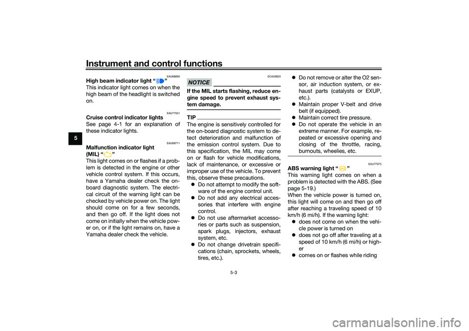
Turn si gnal in dicator li ghts β β
an dββ
Each indicator light will flash when its
corresponding turn signal lights are
flashing.1. High beam indicator light β β
2. Traction control system indicator light β β
3. Turn signal indicator lights β β and β β
4. Smart key system indicator light β β
5. ABS warning light β β
6. Malfunction indicator light β β
7. Cruise control indicator lights
1 2 4 5 6
3
7
12
45 6
3
7
UB3TE1E0.book Page 2 Friday, September 11, 2020 8:48 AM
Page 38 of 124

Instrument and control functions
5-3
5
EAU88690
Hi gh beam in dicator li ght β β
This indicator light comes on when the
high beam of the headlight is switched
on.
EAU77551
Cruise control in dicator li ghts
See page 4-1 for an explanation of
these indicator lights.
EAU88711
Malfunction in dicator li ght
(MIL) β β
This light comes on or flashes if a prob-
lem is detected in the engine or other
vehicle control system. If this occurs,
have a Yamaha dealer check the on-
board diagnostic system. The electri-
cal circuit of the warning light can be
checked by vehicle power on. The light
should come on for a few seconds,
and then go off. If the light does not
come on initially when the vehicle pow-
er on, or if the light remains on, have a
Yamaha dealer check the vehicle.
NOTICE
ECA26820
If the MIL starts flashin g, re duce en-
g ine spee d to prevent exhaust sys-
tem damag e.TIPThe engine is sensitively controlled for
the on-board diagnostic system to de-
tect deterioration and malfunction of
the emission control system. Due to
this specification, the MIL may come
on or flash for vehicle modifications,
lack of maintenance, or excessive or
improper use of the vehicle. To prevent
this, observe these precautions.
ο¬ Do not attempt to modify the soft-
ware of the engine control unit.
ο¬ Do not add any electrical acces-
sories that interfere with engine
control.
ο¬ Do not use aftermarket accesso-
ries or parts such as suspension,
spark plugs, injectors, exhaust
system, etc.
ο¬ Do not change drivetrain specifi-
cations (chain, sprockets, wheels,
tires, etc.). ο¬
Do not remove or alter the O2 sen-
sor, air induction system, or ex-
haust parts (catalysts or EXUP,
etc.).
ο¬ Maintain proper V-belt and drive
belt (if equipped).
ο¬ Maintain correct tire pressure.
ο¬ Do not operate the vehicle in an
extreme manner. For example, re-
peated or excessive opening and
closing of the throttle, racing,
burnouts, wheelies, etc.
EAU77075
ABS warnin g li ght β β
This warning light comes on when a
problem is detected with the ABS. (See
page 5-19.)
When the vehicle power is turned on,
this light will come on and then go off
after reaching a traveling speed of 10
km/h (6 mi/h). If the warning light: ο¬ does not come on when the vehi-
cle power is turned on
ο¬ does not go off after traveling at a
speed of 10 km/h (6 mi/h) or high-
er
ο¬ comes on or flashes while riding
UB3TE1E0.book Page 3 Friday, September 11, 2020 8:48 AM
Page 103 of 124

Periodic maintenance an d a djustment
8-32
8
EAU81473
Replacin g the fusesFuse box1, brake light fuse and cruise
control fuse are located behind panel
A. (See page 8-9.)
Fuse box 2 and main fuse are located
behind the windshield.
TIPTo access the main fuse, remove the
starter relay cover.To access fuse box 2 and the main
fuse, proceed as follows.
1. Remove panel A. (See page 8-9.) 2. Remove the screw access covers
by removing the quick fasteners.
3. Remove the caps.
4. Remove the windshield by remov- ing the screws.
1. Fuse box 1
2. ABS control unit fuse
3. Auxiliary DC jack fuse
4. Headlight fuse
5. Electronic throttle valve fuse
6. ABS motor fuse
7. ABS solenoid fuse
8. Spare fuse
9. Cruise control fuse
10.Brake light fuse2
3
4
5
6
7
8
8
9
10
1 1
1. Starter relay cover
2. Main fuse
3. Spare main fuse
4. Fuse box 2
5. Signaling system fuse
6. Ignition fuse
7. Taillight fuse
8. Radiator fan motor fuse
9. Fuel injection system fuse
10.Backup fuse
11.Spare fuse
12.Windshield motor fuse
5
6
7
8
9
10
11 12 11
1 1
2
3
2
3
4 4
1. Screw access cover
2. Quick fastener
1. Cap
1
212
1
UB3TE1E0.book Page 32 Friday, September 11, 2020 8:48 AM
Page 104 of 124

Periodic maintenance an d a djustment
8-33
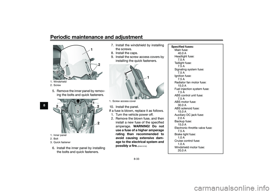
8 5. Remove the inner panel by remov-
ing the bolts and quick fasteners.
6. Install the inner panel by installing the bolts and quick fasteners. 7. Install the windshield by installing
the screws.
8. Install the caps.
9. Install the screw access covers by installing the quick fasteners.
10. Install the panel.
If a fuse is blown, replace it as follows. 1. Turn the vehicle power off.
2. Remove the blown fuse, and then install a new fuse of the specified
amperage. WARNING! Do not
use a fuse of a hi gher ampera ge
ratin g than recommen ded to
avoi d causin g extensive d am-
a g e to the electrical system an d
possi bly a fire.
[EWA15132]
1. Windshield
2. Screw
1. Inner panel
2. Bolt
3. Quick fastener
1
2
2 21 2
2
3 3
2
1. Screw access cover
1
Specified fuses:
Main fuse:
40.0 A
Headlight fuse:
7.5 A
Taillight fuse: 7.5 A
Signaling system fuse: 7.5 A
Ignition fuse:
7.5 A
Radiator fan motor fuse: 15.0 A
Fuel injection system fuse: 7.5 A
ABS control unit fuse:
7.5 A
ABS motor fuse: 30.0 A
ABS solenoid fuse: 15.0 A
Auxiliary DC jack fuse:
2.0 A
Backup fuse: 15.0 A
Electronic throttle valve fuse: 7.5 A
Brake light fuse:
1.0 A
Cruise control fuse: 1.0 A
Windshield motor fuse: 20.0 A
UB3TE1E0.book Page 33 Friday, September 11, 2020 8:48 AM
Page 121 of 124

12-1
12
Index
AABS warning light ................................... 5-3
Acceleration and deceleration ................ 7-3
Air filter element and check hose,
replacing and cleaning ....................... 8-17
Air filter element, V-belt ........................ 8-18
Anti-lock brake system (ABS)............... 5-19
Auxiliary DC jack .................................. 5-26BBattery .................................................. 8-30
Brake fluid, changing............................ 8-26
Brake fluid level, checking.................... 8-25
Brake lever, front .................................. 5-17
Brake lever, rear ................................... 5-18
Brake levers, lubricating ....................... 8-28
Braking ................................................... 7-3CCables, checking and lubricating ......... 8-27
Canister ................................................ 8-12
Care ........................................................ 9-1
Catalytic converter ............................... 5-22
Centerstand and sidestand, checking and lubricating ................................... 8-28
Coolant ................................................. 8-15
Cruise control indicator lights................. 5-3
Cruise control switches .......................... 5-2
Cruise control system............................. 4-1DData recording, vehicle......................... 11-2
Diagnostic connector ........................... 11-2
Dimmer/Pass switch............................... 5-1
D-mode (drive mode).............................. 4-3
Drive belt .............................................. 8-26
Drive mode switch .................................. 5-2
EEmergency mode ................................. 8-39
Engine break-in ...................................... 7-1
Engine idling speed, checking ............. 8-18
Engine oil and oil filter cartridge........... 8-12
Engine overheating .............................. 8-38
Engine serial number ........................... 11-1
Engine stop switch................................. 5-2FFront and rear brake lever free play, checking ............................................ 8-22
Front and rear brake pads, checking ... 8-24
Front fork, checking ............................. 8-29
Fuel ...................................................... 5-20
Fuel consumption, tips for reducing ...... 7-4
Fuel tank cap........................................ 5-20
Fuel tank overflow hose ....................... 5-22
Fuses, replacing ................................... 8-32HHandlebar switches ............................... 5-1
Hazard switch ........................................ 5-2
High beam indicator light ....................... 5-3
Horn switch ............................................ 5-1
How to lock the centerstand ................ 3-10
How to lock the steering ........................ 3-9IIdentification numbers ......................... 11-1
Ignition circuit cut-off system .............. 5-28
Indicator lights and warning lights ......... 5-2KKey, handling of smart and mechanical key ....................................................... 3-3LLicense plate light bulb, replacing ....... 8-34
MMaintenance and lubrication, periodic ... 8-5
Maintenance, emission control system .................................................. 8-3
Malfunction indicator light (MIL) ............. 5-3
Matte color, caution................................ 9-1
Menu switch ........................................... 5-2
Model label ........................................... 11-1
Multi-function display ............................. 5-5OOperating range of the smart key system .................................................. 3-2PPanels, removing and installing .............. 8-9
Parking.................................................... 7-4
Parking mode ....................................... 3-13
Part locations.......................................... 2-1
Powering off the vehicle ......................... 3-8
Powering on the vehicle ......................... 3-7
Power on/Starter switch ......................... 5-2RRear brake lock cable, adjusting .......... 8-23
Rear brake lock, checking .................... 8-23
Rear brake lock lever ............................ 5-18
Rear view mirrors .................................. 5-24SSafe-riding points ................................... 1-5
Safety information................................... 1-1
Select switch .......................................... 5-2
Shock absorber assembly .................... 5-25
Sidestand.............................................. 5-27
Smart key................................................ 3-5
Smart key battery, replacing................... 3-6
Smart key system ................................... 3-1
UB3TE1E0.book Page 1 Friday, September 11, 2020 8:48 AM