YAMAHA TRACER 900 GT 2019 Workshop Manual
Manufacturer: YAMAHA, Model Year: 2019, Model line: TRACER 900 GT, Model: YAMAHA TRACER 900 GT 2019Pages: 120, PDF Size: 9.7 MB
Page 51 of 120
Instrument and control functions
3-36
3
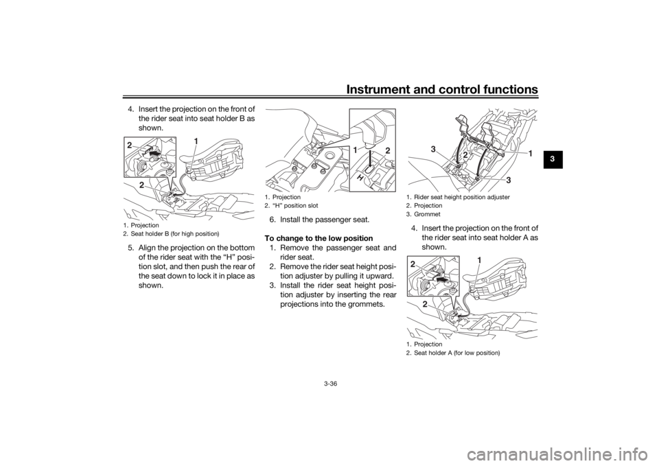
4. Insert the projection on the front of
the rider seat into seat holder B as
shown.
5. Align the projection on the bottom of the rider seat with the “H” posi-
tion slot, and then push the rear of
the seat down to lock it in place as
shown. 6. Install the passenger seat.
To chan ge to the low position
1. Remove the passenger seat and rider seat.
2. Remove the rider seat height posi- tion adjuster by pulling it upward.
3. Install the rider seat height posi- tion adjuster by inserting the rear
projections into the grommets. 4. Insert the projection on the front of
the rider seat into seat holder A as
shown.
1. Projection
2. Seat holder B (for high position)
2 1
2
1. Projection
2. “H” position slot
1
2
1. Rider seat height position adjuster
2. Projection
3. Grommet
1. Projection
2. Seat holder A (for low position)
1
2
3
3
2 1
2
UB1JE1E0.book Page 36 Thursday, October 11, 2018 10:43 AM
Page 52 of 120
Instrument and control functions
3-37
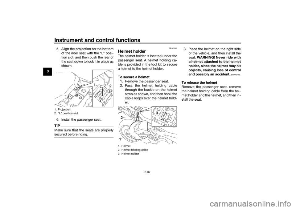
3 5. Align the projection on the bottom
of the rider seat with the “L” posi-
tion slot, and then push the rear of
the seat down to lock it in place as
shown.
6. Install the passenger seat.
TIPMake sure that the seats are properly
secured before riding.
EAU63062
Helmet hold erThe helmet holder is located under the
passenger seat. A helmet holding ca-
ble is provided in the tool kit to secure
a helmet to the helmet holder.
To secure a helmet
1. Remove the passenger seat.
2. Pass the helmet holding cable through the buckle on the helmet
strap as shown, and then hook the
cable loops over the helmet hold-
er. 3. Place the helmet on the right side
of the vehicle, and then install the
seat. WARNING! Never ri de with
a helmet attached to the helmet
hol der, since the helmet may hit
o bjects, causin g loss of control
an d possi bly an acci dent.
[EWA10162]
To release the helmet
Remove the passenger seat, remove
the helmet holding cable from the hel-
met holder and the helmet, and then in-
stall the seat.
1. Projection
2. “L” position slot
1
2
1. Helmet
2. Helmet holding cable
3. Helmet holder
3
21
UB1JE1E0.book Page 37 Thursday, October 11, 2018 10:43 AM
Page 53 of 120
Instrument and control functions
3-38
3
EAU62550
Stora ge compartmentThe storage compartment is located
under the passenger seat. (See page
3-34.)
When storing documents or other
items in the storage compartment, be
sure to wrap them in a plastic bag so
that they will not get wet. When wash-
ing the vehicle, be careful not to let any
water enter the storage compartment.
WARNING
EWA15401
Do not exceed the maximum loa d of
179 k g (395 l b) for the vehicle.
EAU83932
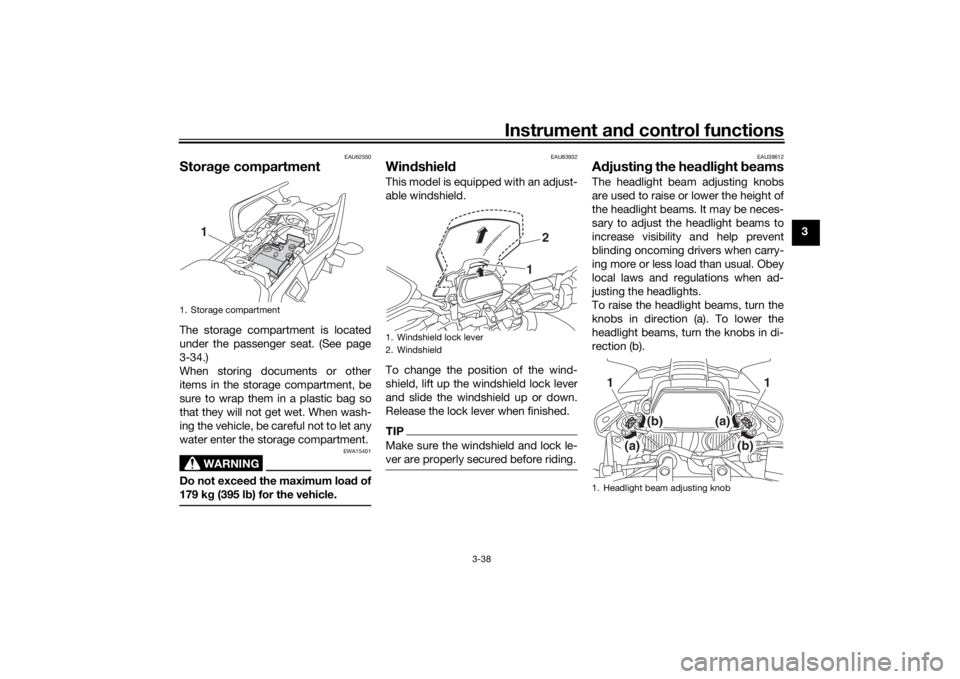
Win dshiel d This model is equipped with an adjust-
able windshield.
To change the position of the wind-
shield, lift up the windshield lock lever
and slide the windshield up or down.
Release the lock lever when finished.TIPMake sure the windshield and lock le-
ver are properly secured before riding.
EAU39612
A djustin g the hea dlig ht beamsThe headlight beam adjusting knobs
are used to raise or lower the height of
the headlight beams. It may be neces-
sary to adjust the headlight beams to
increase visibility and help prevent
blinding oncoming drivers when carry-
ing more or less load than usual. Obey
local laws and regulations when ad-
justing the headlights.
To raise the headlight beams, turn the
knobs in direction (a). To lower the
headlight beams, turn the knobs in di-
rection (b).
1. Storage compartment
1
1. Windshield lock lever
2. Windshield
1 2
1. Headlight beam adjusting knob
(a)
(b)
1
(b)
(a)
1
UB1JE1E0.book Page 38 Thursday, October 11, 2018 10:43 AM
Page 54 of 120
Instrument and control functions
3-39
3
EAU46833
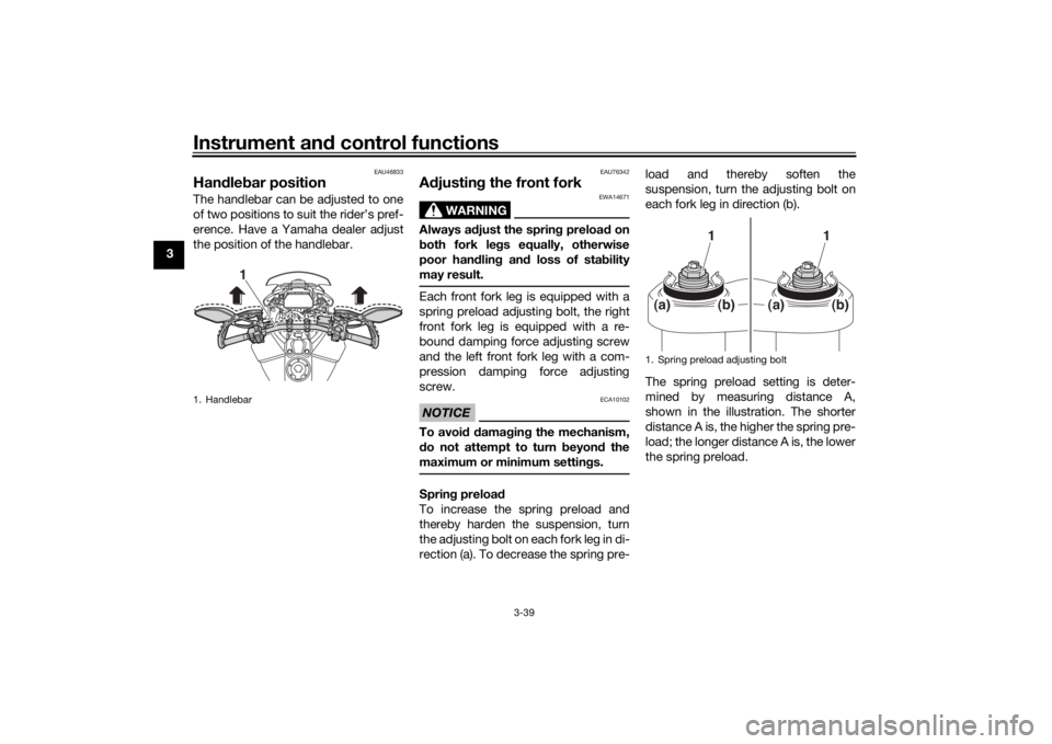
Han dle bar position The handlebar can be adjusted to one
of two positions to suit the rider’s pref-
erence. Have a Yamaha dealer adjust
the position of the handlebar.
EAU76342
A djustin g the front fork
WARNING
EWA14671
Always a djust the sprin g preloa d on
b oth fork le gs equally, otherwise
poor han dlin g an d loss of sta bility
may result.Each front fork leg is equipped with a
spring preload adjusting bolt, the right
front fork leg is equipped with a re-
bound damping force adjusting screw
and the left front fork leg with a com-
pression damping force adjusting
screw.NOTICE
ECA10102
To avoi d d amag ing the mechanism,
d o not attempt to turn b eyond the
maximum or minimum settin gs.Sprin g preloa d
To increase the spring preload and
thereby harden the suspension, turn
the adjusting bolt on each fork leg in di-
rection (a). To decrease the spring pre- load and thereby soften the
suspension, turn the adjusting bolt on
each fork leg in direction (b).
The spring preload setting is deter-
mined by measuring distance A,
shown in the illustration. The shorter
distance A is, the higher the spring pre-
load; the longer distance A is, the lower
the spring preload.
1. Handlebar
1
1. Spring preload adjusting bolt
1
1
(a)
(b)
(a)
(b)
UB1JE1E0.book Page 39 Thursday, October 11, 2018 10:43 AM
Page 55 of 120
Instrument and control functions
3-40
3
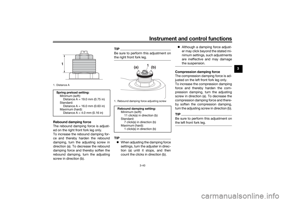
Re boun d d ampin g force
The rebound damping force is adjust-
ed on the right front fork leg only.
To increase the rebound damping for-
ce and thereby harden the rebound
damping, turn the adjusting screw in
direction (a). To decrease the rebound
damping force and thereby soften the
rebound damping, turn the adjusting
screw in direction (b).
TIPBe sure to perform this adjustment on
the right front fork leg.TIP When adjusting the damping force
settings, turn the adjuster in direc-
tion (a) until it stops, and then
count the clicks in direction (b).
Although a damping force adjust-
er may click beyond the stated mi-
nimum settings, such adjustments
are ineffective and may damage
the suspension.
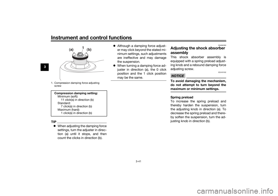
Compression dampin g force
The compression damping force is ad-
justed on the left front fork leg only.
To increase the compression damping
force and thereby harden the com-
pression damping, turn the adjusting
screw in direction (a). To decrease the
compression damping force and there-
by soften the compression damping,
turn the adjusting screw in direction (b).TIPBe sure to perform this adjustment on
the left front fork leg.
1. Distance ASprin g preloa d settin g:
Minimum (soft): Distance A = 19.0 mm (0.75 in)
Standard: Distance A = 16.0 mm (0.63 in)
Maximum (hard):
Distance A = 4.0 mm (0.16 in)
1
1. Rebound damping force adjusting screw
Re boun d d ampin g settin g:
Minimum (soft): 11 click(s) in direction (b)
Standard: 7 click(s) in direction (b)
Maximum (hard):
1 click(s) in direction (b)
1
(a)
(b)
UB1JE1E0.book Page 40 Thursday, October 11, 2018 10:43 AM
Page 56 of 120
Instrument and control functions
3-41
3
TIP When adjusting the damping force
settings, turn the adjuster in direc-
tion (a) until it stops, and then
count the clicks in direction (b).
Although a damping force adjust-
er may click beyond the stated mi-
nimum settings, such adjustments
are ineffective and may damage
the suspension.
When turning a damping force ad-
juster in direction (a), the 0 click
position and the 1 click position
may be the same.
EAU84350
Adjustin g the shock a bsorb er
assem blyThis shock absorber assembly is
equipped with a spring preload adjust-
ing knob and a rebound damping force
adjusting screw.NOTICE
ECA10102
To avoi d d amag ing the mechanism,
d o not attempt to turn b eyond the
maximum or minimum settin gs.Sprin g preloa d
To increase the spring preload and
thereby harden the suspension, turn
the adjusting knob in direction (a). To
decrease the spring preload and there-
by soften the suspension, turn the ad-
justing knob in direction (b).
1. Compression damping force adjusting screwCompression dampin g settin g:
Minimum (soft): 11 click(s) in direction (b)
Standard: 7 click(s) in direction (b)
Maximum (hard):
1 click(s) in direction (b)
1
(a) (b)
UB1JE1E0.book Page 41 Thursday, October 11, 2018 10:43 AM
Page 57 of 120

Instrument and control functions
3-42
3
TIPWhen adjusting the spring preload set-
ting, turn the adjuster in direction (b)
until it stops, and then count the clicks
in direction (a).Re boun d d ampin g force
To increase the rebound damping for-
ce and thereby harden the rebound
damping, turn the adjusting screw in direction (a). To decrease the rebound
damping force and thereby soften the
rebound damping, turn the adjusting
screw in direction (b).
TIP
When adjusting the damping force
settings, turn the adjuster in direc-
tion (a) until it stops, and then
count the clicks in direction (b).
Although a damping force adjust-
er may click beyond the stated mi-
nimum settings, such adjustments
are ineffective and may damage
the suspension.
WARNING
EWA10222
This shock a bsor ber assem bly con-
tains hig hly pressurize d nitro gen
g as. Rea d an d un derstan d the fol-
lowin g information before han dlin g
the shock a bsor ber assem bly.
Do not tamper with or attempt
to open the cylind er assembly.
Do not su bject the shock a b-
sor ber assem bly to an open
flame or other hi gh heat source.
This may cause the unit to ex-
plo de due to excessive gas
pressure.
Do not deform or damag e the
cylin der in any way. Cylin der
d ama ge will result in poor
d ampin g performance.
1. Spring preload adjusting knobSprin g preloa d settin g:
Minimum (soft): 1 clicks in direction (a)
Standard: 11 clicks in direction (a)
Maximum (hard):
24 clicks in direction (a)
(b)
(a)
1
1. Rebound damping force adjusting screw
Re boun d d ampin g settin g:
Minimum (soft): 18 clicks in direction (b)
Standard: 7 clicks in direction (b)
Maximum (hard):
1 clicks in direction (b)
1(a)(b)
UB1JE1E0.book Page 42 Thursday, October 11, 2018 10:43 AM
Page 58 of 120
Instrument and control functions
3-43
3
Do not dispose of a damag ed or
worn-out shock a bsor ber as-
sem bly yourself. Take the shock
a b sor ber assem bly to a Yamaha
d ealer for any service.
EAU49454
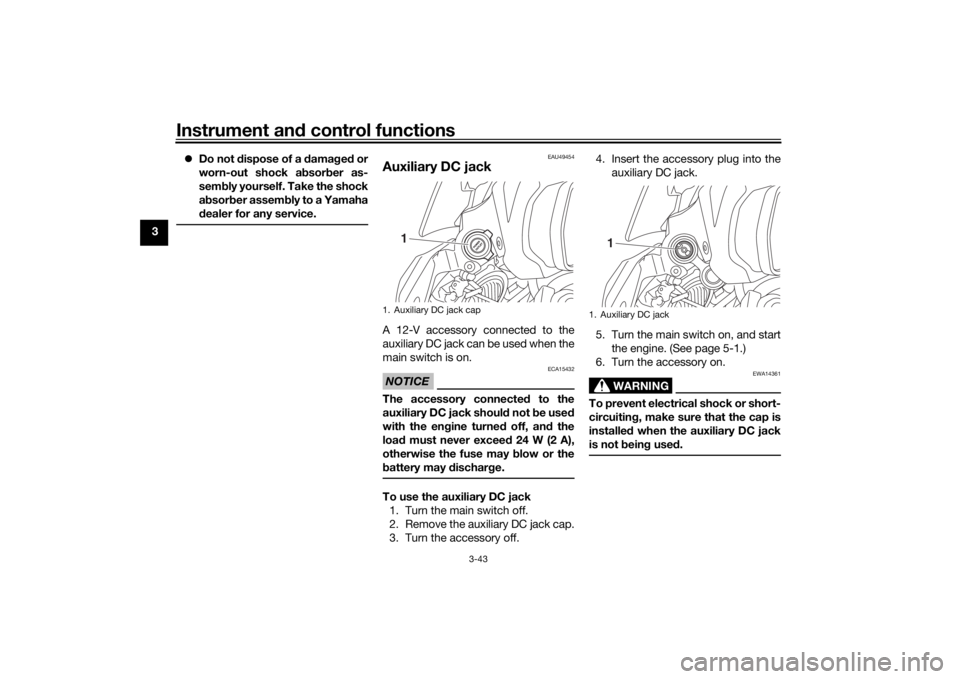
Auxiliary DC jackA 12-V accessory connected to the
auxiliary DC jack can be used when the
main switch is on.NOTICE
ECA15432
The accessory connecte d to the
auxiliary DC jack shoul d not b e used
with the en gine turne d off, an d the
loa d must never excee d 24 W (2 A),
otherwise the fuse may blow or the
b attery may d ischarge.To use the auxiliary DC jack
1. Turn the main switch off.
2. Remove the auxiliary DC jack cap.
3. Turn the accessory off. 4. Insert the accessory plug into the
auxiliary DC jack.
5. Turn the main switch on, and start the engine. (See page 5-1.)
6. Turn the accessory on.
WARNING
EWA14361
To prevent electrical shock or short-
circuitin g, make sure that the cap is
installe d when the auxiliary DC jack
is not bein g use d.
1. Auxiliary DC jack cap
1
1. Auxiliary DC jack
1
UB1JE1E0.book Page 43 Thursday, October 11, 2018 10:43 AM
Page 59 of 120

Instrument and control functions
3-44
3
EAU70641
Auxiliary DC connectorThis vehicle is equipped with an auxil-
iary DC connector. Consult your
Yamaha dealer before installing any accessories.
EAU15306
Si destan dThe sidestand is located on the left
side of the frame. Raise the sidestand
or lower it with your foot while holding
the vehicle upright.TIPThe built-in sidestand switch is part of
the ignition circuit cut-off system,
which cuts the ignition in certain situa-
tions. (See the following section for an
explanation of the ignition circuit cut-
off system.)
WARNING
EWA10242
The vehicle must not b e ridden with
the si destan d d own, or if the si de-
stan d cannot b e properly move d up
(or does not stay up), otherwise the
si destan d coul d contact the groun d
an d d istract the operator, resultin g
in a possib le loss of control.
Yamaha’s ig nition circuit cut-off
system has been desi gne d to assist
the operator in fulfillin g the respon-
si bility of raisin g the si destan d b e-
fore startin g off. Therefore, check this system re
gularly an d have a
Yamaha dealer repair it if it does not
function properly.
UB1JE1E0.book Page 44 Thursday, October 11, 2018 10:43 AM
Page 60 of 120

Instrument and control functions
3-45
3
EAU57952
Ig nition circuit cut-off systemThis system prevents in-gear engine
starts unless the clutch lever is pulled
and the sidestand is up. Also, it will
stop the running engine should the
sidestand be lowered while the trans-
mission is in gear.
Periodically check this system via the
following procedure.TIP This check is most reliable if per-
formed with a warmed-up engine.
See pages 3-2 and 3-3 for switch
operation information.
UB1JE1E0.book Page 45 Thursday, October 11, 2018 10:43 AM