oil YAMAHA TTR110 2013 Owners Manual
[x] Cancel search | Manufacturer: YAMAHA, Model Year: 2013, Model line: TTR110, Model: YAMAHA TTR110 2013Pages: 88, PDF Size: 2.02 MB
Page 9 of 88

TABLE OF CONTENTS
LOCATION OF IMPORTANT
LABELS ............................................1-1
SAFETY INFORMATION .................. 2-1
DESCRIPTION .................................. 3-1
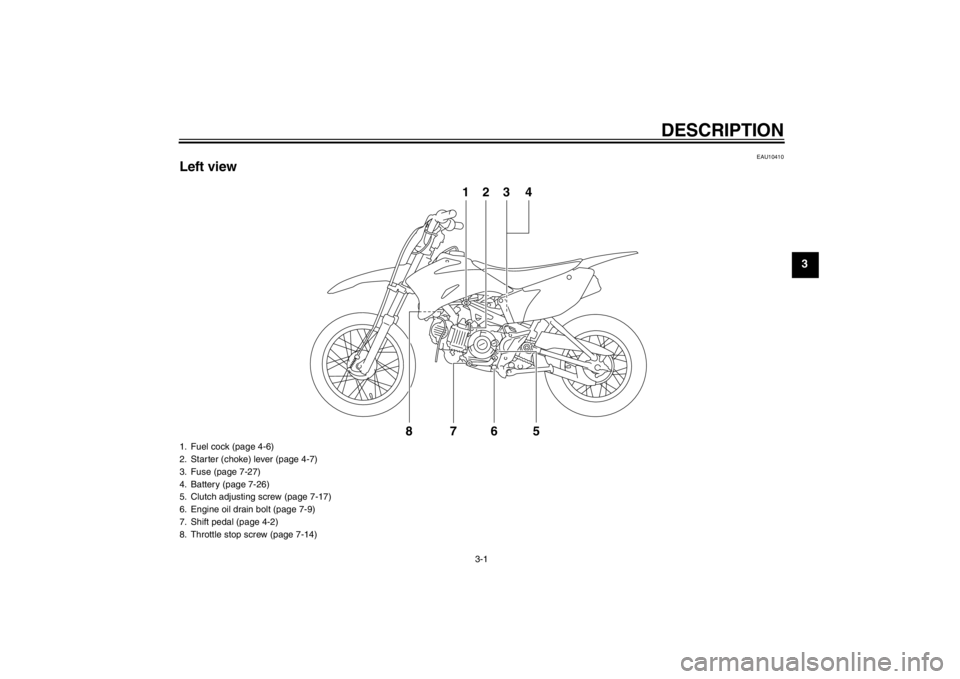
Left view .......................................... 3-1
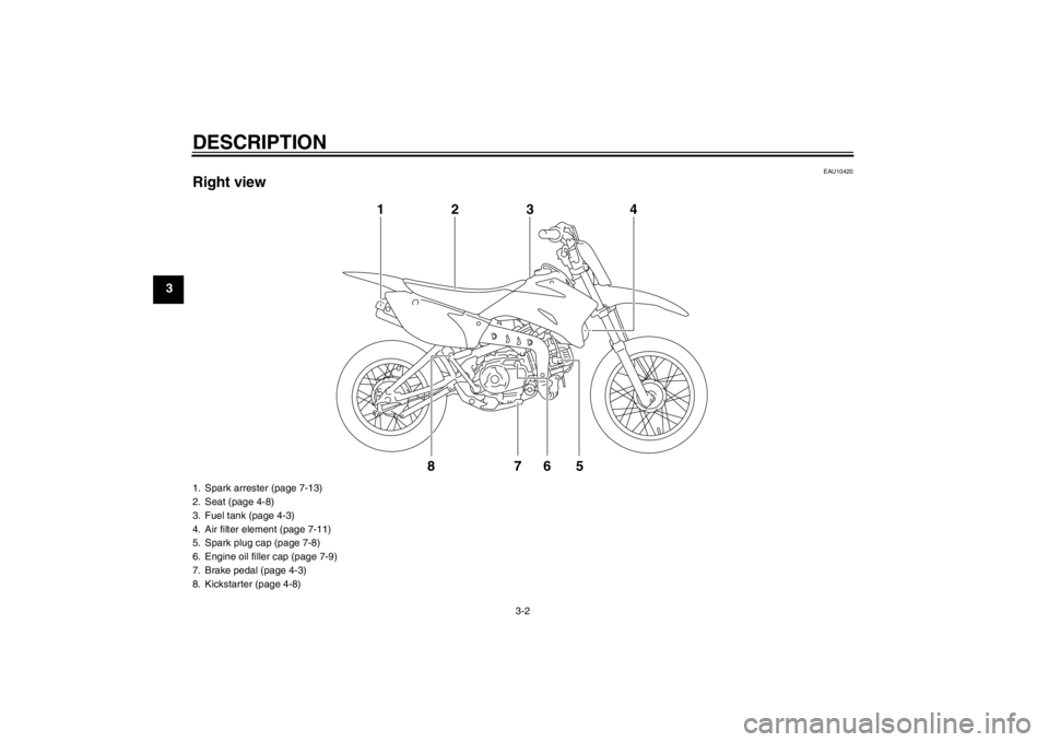
Right view ........................................ 3-2
Controls and instruments ................3-3
INSTRUMENT AND CONTROL
FUNCTIONS ....................................... 4-1
Main switch ..................................... 4-1
Handlebar switches ........................ 4-1
Shift pedal ......................................4-2
Brake lever ..................................... 4-2
Brake pedal .................................... 4-3
Fuel tank cap .................................. 4-3
Fuel ................................................ 4-3
Fuel tank breather hose ................. 4-6
Fuel cock ........................................ 4-6
Starter (choke) lever ....................... 4-7
Kickstarter ......................................4-8
Seat ................................................ 4-8
Shock absorber assembly .............. 4-9
Sidestand ....................................... 4-9
Starting circuit cut-off system ......... 4-9 FOR YOUR SAFETY –
PRE-OPERATION CHECKS
............. 5-1
OPERATION AND IMPORTANT
RIDING POINTS ................................ 6-1
Starting and warming up a cold engine ......................................... 6-1
Starting a warm engine .................. 6-2
Shifting ........................................... 6-2
Engine break-in .............................. 6-3
Parking ........................................... 6-4
PERIODIC MAINTENANCE AND
ADJUSTMENT ................................... 7-1
Owner’s tool kit .............................. 7-2
Periodic maintenance chart for the emission control system ............. 7-3
General maintenance and lubrication chart .......................... 7-4
Removing and installing panels ..... 7-7
Checking the spark plug ................ 7-8
Engine oil ....................................... 7-9
Cleaning the air filter element ...... 7-11
Cleaning the spark arrester ......... 7-13
Adjusting the carburetor ............... 7-14
Adjusting the engine idling
speed ........................................ 7-14
Checking the throttle grip free play ........................................... 7-15
Valve clearance ........................... 7-15
Tires ............................................. 7-15 Spoke wheels ............................... 7-17
Adjusting the clutch free play ....... 7-17
Adjusting the brake lever free
play ........................................... 7-18
Adjusting the brake pedal free
play ........................................... 7-19
Checking the shift pedal ............... 7-20
Checking the front and rear brake shoes ........................................ 7-20
Drive chain slack .......................... 7-21
Cleaning and lubricating the drive chain ......................................... 7-22
Checking and lubricating the cables ....................................... 7-23
Checking and lubricating the throttle grip and cable ............... 7-23
Checking and lubricating the
brake lever ................................ 7-23
Checking and lubricating the brake pedal ............................... 7-24
Checking and lubricating the sidestand .................................. 7-24
Lubricating the swingarm pivots ... 7-24
Checking the front fork ................. 7-25
Checking the steering .................. 7-25
Checking the wheel bearings ....... 7-26
Battery .......................................... 7-26
Replacing the fuse ....................... 7-27
Supporting the motorcycle ........... 7-28
Front wheel .................................. 7-29
Rear wheel ................................... 7-30
U5B685E0.book Page 1 Tuesday, July 10, 2012 5:06 PM
Page 25 of 88
DESCRIPTION
3-1
3
EAU10410
Left view
678
123 4
5
1. Fuel cock (page 4-6)
2. Starter (choke) lever (page 4-7)
3. Fuse (page 7-27)
4. Battery (page 7-26)
5. Clutch adjusting screw (page 7-17)
6. Engine oil drain bolt (page 7-9)
7. Shift pedal (page 4-2)
8. Throttle stop screw (page 7-14)
U5B685E0.book Page 1 Tuesday, July 10, 2012 5:06 PM
Page 26 of 88
DESCRIPTION
3-2
3
EAU10420
Right view
12 3 485 7
6
1. Spark arrester (page 7-13)
2. Seat (page 4-8)
3. Fuel tank (page 4-3)
4. Air filter element (page 7-11)
5. Spark plug cap (page 7-8)
6. Engine oil filler cap (page 7-9)
7. Brake pedal (page 4-3)
8. Kickstarter (page 4-8)U5B685E0.book Page 2 Tuesday, July 10, 2012 5:06 PM
Page 38 of 88
FOR YOUR SAFETY – PRE-OPERATION CHECKS
5-1
5
EAU15596
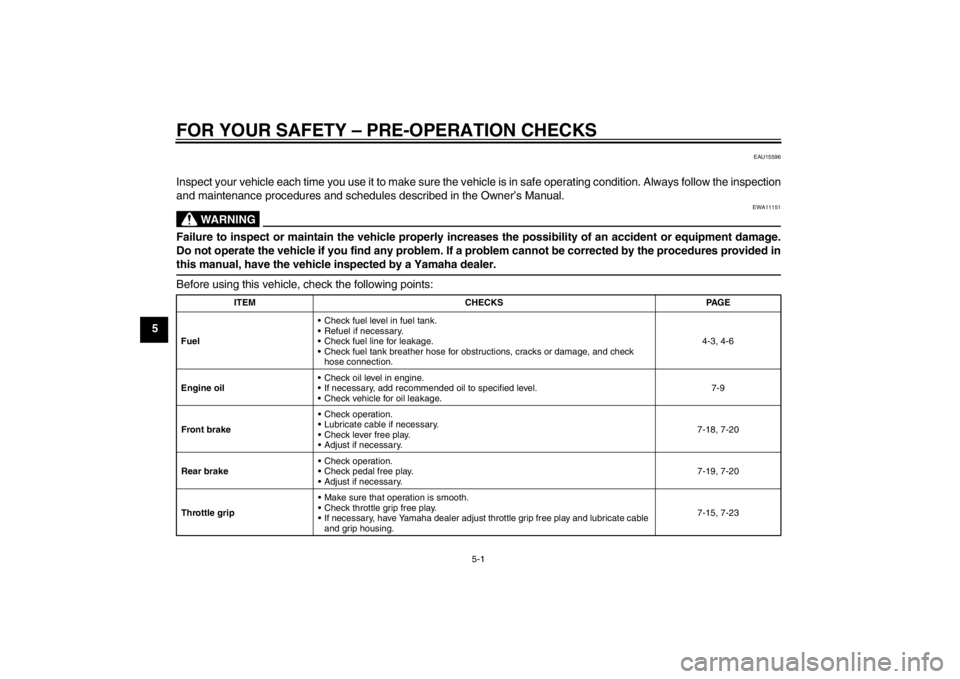
Inspect your vehicle each time you use it to make sure the vehicle is in safe operating condition. Always follow the inspection
and maintenance procedures and schedules described in the Owner’s Manual.
WARNING
EWA11151
Failure to inspect or maintain the vehicle properly increases the possibility of an accident or equipment damage.
Do not operate the vehicle if you find any problem. If a problem cannot be corrected by the procedures provided in
this manual, have the vehicle inspected by a Yamaha dealer.Before using this vehicle, check the following points:
ITEMCHECKS PAGE
Fuel Check fuel level in fuel tank.
Refuel if necessary.
Check fuel line for leakage.
Check fuel tank breather hose for obs
tructions, cracks or damage, and check
hose connection. 4-3, 4-6
Engine oil Check oil level in engine.
If necessary, add recommended oil to specified level.
Check vehicle for oil leakage. 7-9
Front brake Check operation.
Lubricate cable if necessary.
Check lever free play.
Adjust if necessary.
7-18, 7-20
Rear brake Check operation.
Check pedal free play.
Adjust if necessary. 7-19, 7-20
Throttle grip Make sure that operation is smooth.
Check throttle grip free play.
If necessary, have Yamaha dealer adjust throttle grip free play and lubricate cable
and grip housing. 7-15, 7-23
U5B685E0.book Page 1 Tuesday, July 10, 2012 5:06 PM
Page 42 of 88
OPERATION AND IMPORTANT RIDING POINTS
6-3
63. Open the throttle gradually.
4. Once the motorcycle has reached
a speed high enough to change
gears, close the throttle.
5. Shift into second gear and release the shift pedal.
6. Open the throttle gradually.
7. Follow the same procedure when shifting to the next higher gear.
EAU16710
To decelerate1. Close the throttle and apply both the front and the rear brakes to
slow the motorcycle.
2. Downshift through the gears and shift the transmission into the neu-
tral position when the motorcycle
is almost completely stopped.
EAU39920
Engine break-in There is never a more important period
in the life of your engine than the first 5
hours of riding. It is also important to ac-
custom the rider to the motorcycle dur-
ing this time. Please read the following
information carefully.
Since the engine is brand new, do not
put an excessive load on it for the first 5
hours of operation. The various parts in
the engine wear and polish themselves
to the correct operating clearances.
During this period, prolonged full-throt-
tle operation or any condition that might
result in engine overheating must be
avoided. However, momentary full-
throttle operation under load (i.e., two
to three seconds maximum) does not
harm the engine. Each full-throttle ac-
celeration should be followed with a
substantial rest period for the engine.
To allow the engine to cool down from
the temporary buildup of heat, cruise at
a lower engine speed.
After the first 5 hours of operation, thor-
oughly check the motorcycle for loose
parts, oil leakage and any other prob-
lems. Be sure to inspect and make ad- justments thoroughly, especially cable
and drive chain slack and loose
spokes. In addition, check all fittings
and fasteners for looseness, and tight-
en if necessary.
NOTICE
ECA10270
If any engine trouble should occur
during the engine break-in period,
immediately have a Yamaha dealer
check the vehicle.
U5B685E0.book Page 3 Tuesday, July 10, 2012 5:06 PM
Page 46 of 88

PERIODIC MAINTENANCE AND ADJUSTMENT
7-3
7
EAU39944
Periodic maintenance chart for the emission control system TIP●
From 7000 km (4200 mi) or 18 months, repeat the maintenance intervals starting from 3000 km (1800 mi) or 6 months.
●
Items marked with an asterisk should be performed by a Yamaha dealer as they require special tools, data and technical
skills.
No.ITEM CHECKS AND MAINTENANCE JOBS INITIAL ODOMETER READINGS
1000 km
(600 mi) or
1 month or 30 hours 3000 km
(1800 mi) or
6 months or 90 hours 5000 km
(3000 mi) or
12 months or 150 hours
1 *Fuel line Check fuel hoses for cracks or damage.
Replace if necessary. √√
2 Spark plug Check condition.
Adjust gap and clean.
√√
3 *Valve clearance Check and adjust valve clearance when engine is cold. √
4 Air filter element Clean with solvent.
Replace if necessary. √√
5 *Crankcase breather sys-
tem Check ventilation hose for cracks or damage and drain
any deposits.
Replace if necessary. √√√
6 *Carburetor Check engine idling speed and starter operation.
Adjust if necessary.
√√√
7 Exhaust system Check for leakage.
Tighten if necessary.
Replace gasket(s) if necessary. √√
8 *Spark arrester Clean. √
9 Engine oil Change (warm engine before draining). √√√
U5B685E0.book Page 3 Tuesday, July 10, 2012 5:06 PM
Page 48 of 88

PERIODIC MAINTENANCE AND ADJUSTMENT
7-5
7
8 Drive chain Check chain slack/alignment and condition.
Adjust and lubricate chain with Yamaha chain and cable
lube thoroughly. Every ride
9 *Steering bearings Check bearing assemblies for looseness.
Moderately repack with lit
hium-soap-based grease. √√
10 *Chassis fasteners Check all chassis fitting and fasteners.
Correct if necessary. √√√
11 Brake lever pivot shaft Apply lithium-soap-based grease lightly. √√
12 Brake pedal pivot shaft Apply lithium-soap-based grease lightly. √√
13 Sidestand pivot Check operation.
Apply lithium-soap-based grease lightly. √√
14 *Front fork Check operation and for oil leakage.
Replace if necessary. √√
15 *Shock absorber assem-
bly Check operation and for oil leakage.
Replace if necessary.
√
16 *Control cables Apply Yamaha chain and cable lube or engine oil thor-
oughly. √√√
17 *Throttle grip Check operation.
Check throttle grip free play, and adjust if necessary.
Lubricate cable and grip housing. √√√
No. ITEM CHECKS AND MAINTENANCE JOBS
INITIAL ODOMETER READINGS
1000 km
(600 mi) or
1 month or 30 hours 3000 km
(1800 mi) or
6 months or 90 hours 5000 km
(3000 mi) or
12 months or 150 hours
U5B685E0.book Page 5 Tuesday, July 10, 2012 5:06 PM
Page 52 of 88
PERIODIC MAINTENANCE AND ADJUSTMENT
7-9
72. Check the spark plug for electrode
erosion and excessive carbon or
other deposits, and replace it if
necessary.
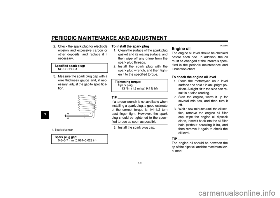
3. Measure the spark plug gap with a wire thickness gauge and, if nec-
essary, adjust the gap to specifica-
tion. To install the spark plug
1. Clean the surface of the spark plug gasket and its mating surface, and
then wipe off any grime from the
spark plug threads.
2. Install the spark plug with the spark plug wrench, and then tight-
en it to the specified torque.
TIPIf a torque wrench is not available when
installing a spark plug, a good estimate
of the correct torque is 1/4–1/2 turn
past finger tight. However, the spark
plug should be tightened to the speci-
fied torque as soon as possible.3. Install the spark plug cap.
EAU39845
Engine oil The engine oil level should be checked
before each ride. In addition, the oil
must be changed at the intervals spec-
ified in the periodic maintenance and
lubrication chart.
To check the engine oil level1. Place the motorcycle on a level surface and hold it in an upright po-
sition. A slight tilt to the side can re-
sult in a false reading.
2. Start the engine, warm it up for several minutes, and then turn it
off.
3. Wait a few minutes until the oil set- tles, remove the engine oil filler
cap, wipe the engine oil dipstick
clean, insert it back into the oil filler
hole (without screwing it in), and
then remove it again to check the
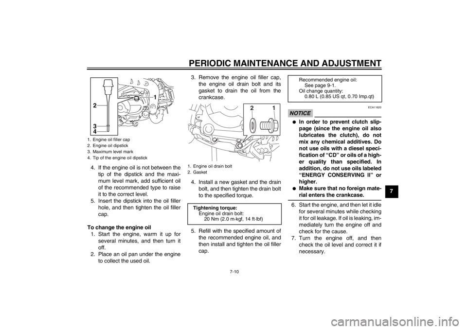
oil level.TIPThe engine oil should be between the
tip of the dipstick and the maximum lev-
el mark.
Specified spark plug:NGK/CR6HSA1. Spark plug gapSpark plug gap:0.6–0.7 mm (0.024–0.028 in)
Tightening torque:
Spark plug:13 Nm (1.3 m·kgf, 9.4 ft·lbf)
U5B685E0.book Page 9 Tuesday, July 10, 2012 5:06 PM
Page 53 of 88
PERIODIC MAINTENANCE AND ADJUSTMENT
7-10
7
4. If the engine oil is not between the
tip of the dipstick and the maxi-
mum level mark, add sufficient oil
of the recommended type to raise
it to the correct level.
5. Insert the dipstick into the oil filler hole, and then tighten the oil filler
cap.
To change the engine oil 1. Start the engine, warm it up for several minutes, and then turn it
off.
2. Place an oil pan under the engine to collect the used oil. 3. Remove the engine oil filler cap,
the engine oil drain bolt and its
gasket to drain the oil from the
crankcase.
4. Install a new gasket and the drain bolt, and then tighten the drain bolt
to the specified torque.
5. Refill with the specified amount of the recommended engine oil, and
then install and tighten the oil filler
cap.
NOTICE
ECA11620
●
In order to prevent clutch slip-
page (since the engine oil also
lubricates the clutch), do not
mix any chemical additives. Do
not use oils with a diesel speci-
fication of “CD” or oils of a high-
er quality than specified. In
addition, do not use oils labeled
“ENERGY CONSERVING II” or
higher.
●
Make sure that no foreign mate-
rial enters the crankcase.
6. Start the engine, and then let it idlefor several minutes while checking
it for oil leakage. If oil is leaking, im-
mediately turn the engine off and
check for the cause.
7. Turn the engine off, and then check the oil level and correct it if
necessary.
1. Engine oil filler cap
2. Engine oil dipstick
3. Maximum level mark
4. Tip of the engine oil dipstick
1
3
4
2
1. Engine oil drain bolt
2. Gasket
Tightening torque: Engine oil drain bolt:20 Nm (2.0 m·kgf, 14 ft·lbf)
1
2
Recommended engine oil: See page 9-1.
Oil change quantity: 0.80 L (0.85 US qt, 0.70 Imp.qt)
U5B685E0.book Page 10 Tuesday, July 10, 2012 5:06 PM
Page 54 of 88
PERIODIC MAINTENANCE AND ADJUSTMENT
7-11
7
EAU41637
Cleaning the air filter element The air filter element should be cleaned
or replaced at the intervals specified in
the periodic maintenance and lubrica-
tion chart. Clean or, if necessary, re-
place the air filter element more
frequently if you are riding in unusually
wet or dusty areas.
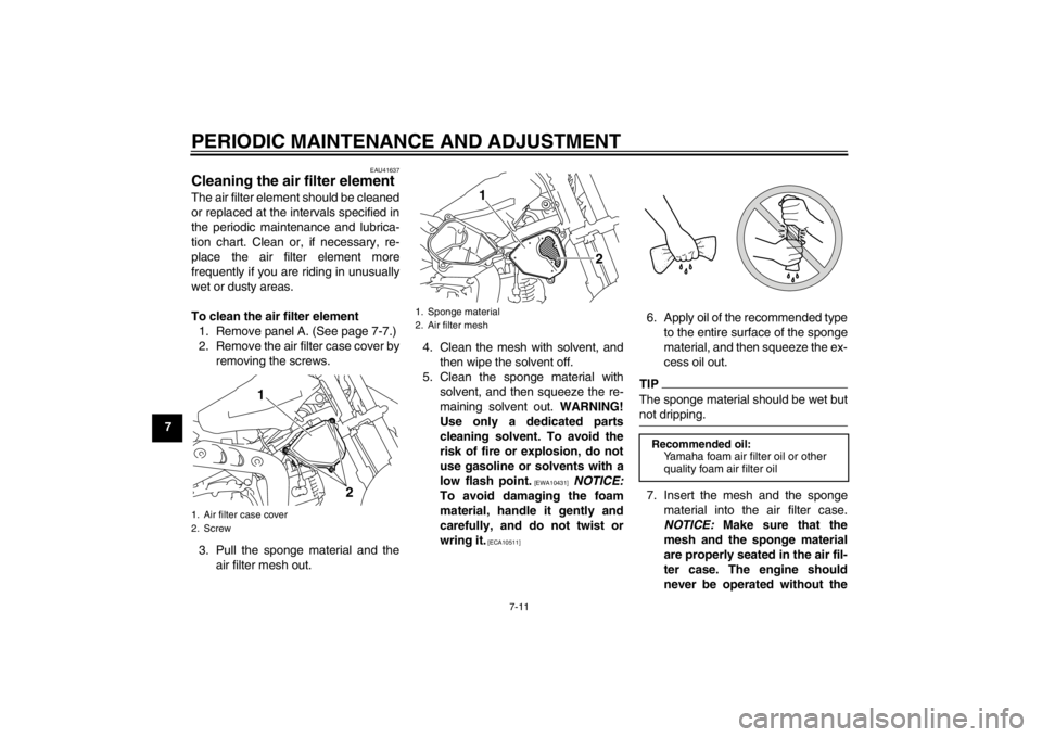
To clean the air filter element1. Remove panel A. (See page 7-7.)
2. Remove the air filter case cover by removing the screws.
3. Pull the sponge material and the air filter mesh out. 4. Clean the mesh with solvent, and
then wipe the solvent off.
5. Clean the sponge material with solvent, and then squeeze the re-
maining solvent out. WARNING!
Use only a dedicated parts
cleaning solvent. To avoid the
risk of fire or explosion, do not
use gasoline or solvents with a
low flash point.
[EWA10431]
NOTICE:
To avoid damaging the foam
material, handle it gently and
carefully, and do not twist or
wring it.
[ECA10511]
6. Apply oil of the recommended type to the entire surface of the sponge
material, and then squeeze the ex-
cess oil out.TIPThe sponge material should be wet but
not dripping.7. Insert the mesh and the spongematerial into the air filter case.
NOTICE: Make sure that the
mesh and the sponge material
are properly seated in the air fil-
ter case. The engine should
never be operated without the
1. Air filter case cover
2. Screw
2
1
1. Sponge material
2. Air filter mesh
1
2
Recommended oil:
Yamaha foam air filter oil or other
quality foam air filter oil
U5B685E0.book Page 11 Tuesday, July 10, 2012 5:06 PM