relay YAMAHA TTR125 2004 Owners Manual
[x] Cancel search | Manufacturer: YAMAHA, Model Year: 2004, Model line: TTR125, Model: YAMAHA TTR125 2004Pages: 610, PDF Size: 25.85 MB
Page 90 of 610

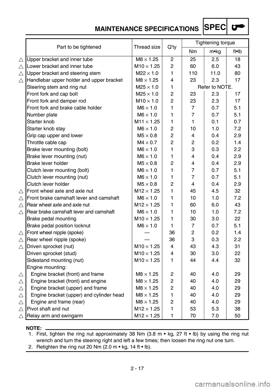
SPEC
2 - 17
MAINTENANCE SPECIFICATIONS
NOTE:
1. First, tighten the ring nut approximately 38 Nm (3.8 m • kg, 27 ft • lb) by using the ring nut
wrench and turn the steering right and left a few times; then loosen the ring nut one turn.
2. Retighten the ring nut 20 Nm (2.0 m • kg, 14 ft • lb). Part to be tightened Thread size Q’tyTightening torque
Nm m•kg ft•lb
Upper bracket and inner tube M8 × 1.25 2 25 2.5 18
Lower bracket and inner tube M10 × 1.25 2 60 6.0 43
Upper bracket and steering stem M22 × 1.0 1 110 11.0 80
Handlebar upper holder and upper bracket M8 × 1.25 4 23 2.3 17
Steering stem and ring nut M25 × 1.0 1 Refer to NOTE.
Front fork and cap bolt M25 × 1.0 2 23 2.3 17
Front fork and damper rod M10 × 1.0 2 23 2.3 17
Front fork and brake cable holder M6 × 1.0 1 7 0.7 5.1
Number plate M6 × 1.0 1 7 0.7 5.1
Starter knob M11 × 1.25 1 1 0.1 0.7
Starter knob stay M6 × 1.0 2 10 1.0 7.2
Grip cap upper and lower M5 × 0.8 2 4 0.4 2.9
Throttle cable cap M4 × 0.7 2 2 0.2 1.4
Brake lever mounting (bolt) M6 × 1.0 1 3 0.3 2.2
Brake lever mounting (nut) M6 × 1.0 1 4 0.4 2.9
Brake lever holder M5 × 0.8 2 4 0.4 2.9
Clutch lever mounting (bolt) M6 × 1.0 1 7 0.7 5.1
Clutch lever mounting (nut) M6 × 1.0 1 7 0.7 5.1
Clutch lever holder M5 × 0.8 2 4 0.4 2.9
Front wheel axle and axle nut M12 × 1.25 1 45 4.5 32
Front brake camshaft lever and camshaft M6 × 1.0 1 10 1.0 7.2
Rear wheel axle and axle nut M12 × 1.25 1 60 6.0 43
Rear brake camshaft lever and camshaft M6 × 1.0 1 10 1.0 7.2
Brake pedal mounting M10 × 1.25 1 30 3.0 22
Brake pedal position locknut M6 × 1.0 1 7 0.7 5.1
Front wheel nipple (spoke)—36 2 0.2 1.4
Rear wheel nipple (spoke)—36 3 0.3 2.2
Driven sprocket (nut) M10 × 1.25 4 43 4.3 31
Driven sprocket (stud) M10 × 1.25 4 30 3.0 22
Sidestand mounting (nut) M10 × 1.25 1 44 4.4 32
Engine mounting:
Engine bracket (front) and frame M8 × 1.25 2 40 4.0 29
Engine bracket (front) and engine M8 × 1.25 2 40 4.0 29
Engine bracket (upper) and frame M8 × 1.25 2 40 4.0 29
Engine bracket (upper) and cylinder head M8 × 1.25 1 40 4.0 29
Engine and frame (rear) M8 × 1.25 2 40 4.0 29
Pivot shaft and nut M12 × 1.25 1 53 5.3 38
Relay arm and swingarm M12 × 1.25 1 70 7.0 50
Page 91 of 610

SPEC
2 - 18
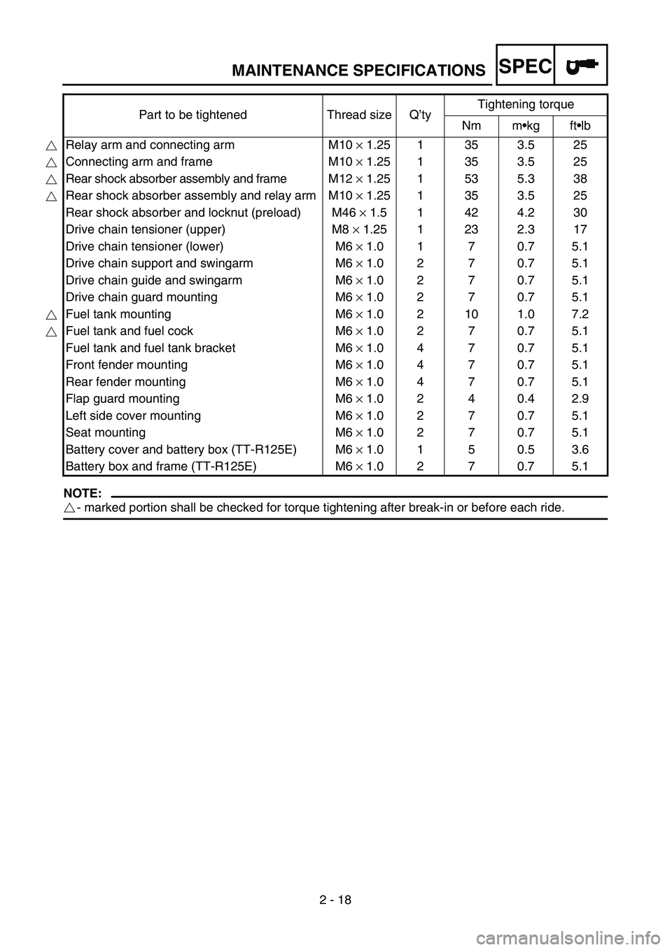
MAINTENANCE SPECIFICATIONS
NOTE:
- marked portion shall be checked for torque tightening after break-in or before each ride.Part to be tightened Thread size Q’tyTightening torque
Nm m•kg ft•lb
Relay arm and connecting arm M10 × 1.25 1 35 3.5 25
Connecting arm and frame M10 × 1.25 1 35 3.5 25
Rear shock absorber assembly and frame M12 × 1.25 1 53 5.3 38
Rear shock absorber assembly and relay arm M10 × 1.25 1 35 3.5 25
Rear shock absorber and locknut (preload) M46 × 1.5 1 42 4.2 30
Drive chain tensioner (upper) M8 × 1.25 1 23 2.3 17
Drive chain tensioner (lower) M6 × 1.0 1 7 0.7 5.1
Drive chain support and swingarm M6 × 1.0 2 7 0.7 5.1
Drive chain guide and swingarm M6 × 1.0 2 7 0.7 5.1
Drive chain guard mounting M6 × 1.0 2 7 0.7 5.1
Fuel tank mounting M6 × 1.0 2 10 1.0 7.2
Fuel tank and fuel cock M6 × 1.0 2 7 0.7 5.1
Fuel tank and fuel tank bracket M6 × 1.0 4 7 0.7 5.1
Front fender mounting M6 × 1.0 4 7 0.7 5.1
Rear fender mounting M6 × 1.0 4 7 0.7 5.1
Flap guard mounting M6 × 1.0 2 4 0.4 2.9
Left side cover mounting M6 × 1.0 2 7 0.7 5.1
Seat mounting M6 × 1.0 2 7 0.7 5.1
Battery cover and battery box (TT-R125E) M6 × 1.0 1 5 0.5 3.6
Battery box and frame (TT-R125E) M6 × 1.0 2 7 0.7 5.1
Page 95 of 610

SPEC
2 - 22
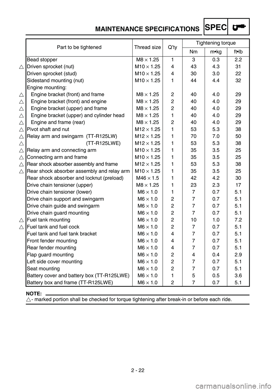
MAINTENANCE SPECIFICATIONS
NOTE:
- marked portion shall be checked for torque tightening after break-in or before each ride.Part to be tightened Thread size Q’tyTightening torque
Nm m•kg ft•lb
Bead stopper M8 × 1.25 1 3 0.3 2.2
Driven sprocket (nut) M10 × 1.25 4 43 4.3 31
Driven sprocket (stud) M10 × 1.25 4 30 3.0 22
Sidestand mounting (nut) M10 × 1.25 1 44 4.4 32
Engine mounting:
Engine bracket (front) and frame M8 × 1.25 2 40 4.0 29
Engine bracket (front) and engine M8 × 1.25 2 40 4.0 29
Engine bracket (upper) and frame M8 × 1.25 2 40 4.0 29
Engine bracket (upper) and cylinder head M8 × 1.25 1 40 4.0 29
Engine and frame (rear) M8 × 1.25 2 40 4.0 29
Pivot shaft and nut M12 × 1.25 1 53 5.3 38
Relay arm and swingarm (TT-R125LW) M12 × 1.25 1 70 7.0 50
(TT-R125LWE) M12 × 1.25 1 53 5.3 38
Relay arm and connecting arm M10 × 1.25 1 35 3.5 25
Connecting arm and frame M10 × 1.25 1 35 3.5 25
Rear shock absorber assembly and frame M12 × 1.25 1 53 5.3 38
Rear shock absorber assembly and relay arm M10 × 1.25 1 35 3.5 25
Rear shock absorber and locknut (preload) M46 × 1.5 1 42 4.2 30
Drive chain tensioner (upper) M8 × 1.25 1 23 2.3 17
Drive chain tensioner (lower) M6 × 1.0 1 7 0.7 5.1
Drive chain support and swingarm M6 × 1.0 2 7 0.7 5.1
Drive chain guide and swingarm M6 × 1.0 2 7 0.7 5.1
Drive chain guard mounting M6 × 1.0 2 7 0.7 5.1
Fuel tank mounting M6 × 1.0 2 10 1.0 7.2
Fuel tank and fuel cock M6 × 1.0 2 7 0.7 5.1
Fuel tank and fuel tank bracket M6 × 1.0 4 7 0.7 5.1
Front fender mounting M6 × 1.0 4 7 0.7 5.1
Rear fender mounting M6 × 1.0 4 7 0.7 5.1
Flap guard mounting M6 × 1.0 2 4 0.4 2.9
Left side cover mounting M6 × 1.0 2 7 0.7 5.1
Seat mounting M6 × 1.0 2 7 0.7 5.1
Battery cover and battery box (TT-R125LWE) M6 × 1.0 1 5 0.5 3.6
Battery box and frame (TT-R125LWE) M6 × 1.0 2 7 0.7 5.1
Page 98 of 610

SPEC
2 - 25
MAINTENANCE SPECIFICATIONS
Starter relay:
Model/manufacturer MS5F-751/JIDECO ----
Amperage rating 180 A ----
Coil winding resistance 4.2 ~ 4.6 Ω at 20 ˚C (68 ˚F) ----
Starting circuit cut-off relay:
Model/manufacturer ACM33221/MATSUSHITA ----
Coil winding resistance 75.69 ~ 92.51 Ω at 20 ˚C (68 ˚F) ----
Fuse (amperage × quantity):
Main fuse 10 A × 1 ----
Reserve fuse 10 A × 1 ----
Part to be tightened Thread size Q’tyTightening torque
Nm m•kg ft•lb
Pickup coil M6 × 1.0 2 10 1.0 7.2
Neutral switch M10 × 1.25 1 18 1.8 13
Stator M6 × 1.0 3 10 1.0 7.2
Rotor M12 × 1.25 1 80 8.0 58
Ignition coil M6 × 1.0 2 7 0.7 5.1
Starter motor M6 × 1.0 2 10 1.0 7.2 Item Standard Limit
Page 158 of 610

2 - 30
SPECCABLE ROUTING DIAGRAM
TT-R125E/TT-R125LWE
1Ground lead
2Primary coil lead
3Clamp
4Wire harness
5Starter relay lead
6Rectifier/regulator lead
7CDI magneto lead
8Air vent hose
9Neutral switch lead
0Rear shock absorber assembly
sub-tank hose (TT-R125LWE
only)
AStarting circuit cut-off relay lead
BCDI unit lead
CCorrugated tubeDBrake hose holder (Brake cable
holder for the TT-R125E)
EBrake hose (Brake cable for the
TT-R125E)
FCable guide
GMain switch lead
HEngine stop switch lead
IClutch switch lead
JStart switch lead
KCDI unit band
LCDI unit
MConnector cover
NRubber cover
OStarter cable
PThrottle cableQRectifier/regulator
ÅFasten the primary coil lead and
ground lead.
ıFasten the wire harness at its
tape.
ÇFasten the wire harness and
CDI magneto lead in front of the
rear shock absorber assembly
bracket at the protecting tube
for the CDI magneto lead.
30~35 mm
(1.18~1.38 in)
E
DD
A
C
B-B
D-D
E
B
BC
TT-R125EA
L
1
3
4 2
3
35
3
36
7
3
3
8
9 0 A 3 B C
DEFGHIJKOP
7
4
0
3 3M
N
3Q
3 F
E
DË
◊
„
Ù
AB
AA
Û
ÁAC
N
Ì
Ï ‰ Î
Ç ı Å
Ó
È
Ô
Ò ˜ ˆ Ø ∏
ŒÂÍ ÊÂ
Page 160 of 610

2 - 31
SPECCABLE ROUTING DIAGRAM
ÎAfter fastening the starter relay
lead, pass it on the left of the
chassis.
‰Fasten the CDI magneto lead
and starter relay lead.
ÏFasten the wire harness.
ÌPass the rectifier/regulator lead
between the frame and air filter
case.
ÓDo not allow the CDI magneto
lead to slacken except between
the two plastic locking ties.
ÈFasten the CDI magneto lead
over the engine bracket (rear).
ÔFasten the CDI magneto lead.Pass the air vent hoses between
the engine and swingarm.
ÒFit the neutral switch lead into
the groove in the crankcase
cover.
˜Pass the starting circuit cut-off
relay lead under the frame and
at the right of the chassis.
ˆFasten the rear shock absorber
assembly sub-tank.
(TT-R125LWE only)
ØPass the CDI unit lead on the
outside of the main switch lead,
engine stop switch lead, clutch
switch lead and start switch
lead.∏After fastening the start switch
lead, clutch switch lead, engine
stop switch lead and main
switch lead, push their corru-
gated tube against the CDI unit
coupler.
ŒFasten the brake hose between
the paint marks.
ÂPass the brake hose (brake
cable for the TT-R125E)
through the cable guide.
ÍFit the CDI unit band over the
CDI unit bracket till it stops.
ÊFasten the brake cable.
30~35 mm
(1.18~1.38 in)
E
DD
A
C
B-B
D-D
E
B
BC
TT-R125EA
L
1
3
4 2
3
35
3
36
7
3
3
8
9 0 A 3 B C
DEFGHIJKOP
7
4
0
3 3M
N
3Q
3 F
E
DË
◊
„
Ù
AB
AA
Û
ÁAC
N
Ì
Ï ‰ Î
Ç ı Å
Ó
È
Ô
Ò ˜ ˆ Ø ∏
ŒÂÍ ÊÂ
Page 162 of 610

2 - 32
SPECCABLE ROUTING DIAGRAM
ËAfter connecting the main
switch coupler, engine stop
switch coupler, clutch switch
coupler and start switch cou-
pler, put a connector cover on
the couplers and push them in
at the rubber cover end.
◊Pass the wire harness on the
outside of the main switch cou-
pler.
„Do not allow the primary coil
lead to slacken where it is bare
of the protecting tube.ÙFasten the CDI unit lead and
starting circuit cut-off relay lead
with a plastic locking tie at the
tape holding the main switch
lead, engine stop switch lead,
clutch switch lead, and start
switch lead together.
ÁPosition the starter cable, throt-
tle cable, CDI magneto lead,
wire harness and rear shock
absorber assembly sub-tank
hose (TT-R125LWE only) as
shown.ÛFasten the wire harness, throttle
cable, starter cable, CDI mag-
neto lead and rear shock
absorber assembly sub-tank
hose (TT-R125LWE only) at the
protecting tube for the CDI mag-
neto lead.
Fasten the rectifier/regulator
lead as shown.
Do not allow the CDI magneto
lead to slacken.
Position the plastic locking tie
ends as shown.
AA
AB
AC
30~35 mm
(1.18~1.38 in)
E
DD
A
C
B-B
D-D
E
B
BC
TT-R125EA
L
1
3
4 2
3
35
3
36
7
3
3
8
9 0 A 3 B C
DEFGHIJKOP
7
4
0
3 3M
N
3Q
3 F
E
DË
◊
„
Ù
AB
AA
Û
ÁAC
N
Ì
Ï ‰ Î
Ç ı Å
Ó
È
Ô
Ò ˜ ˆ Ø ∏
ŒÂÍ ÊÂ
Page 164 of 610

2 - 33
SPEC
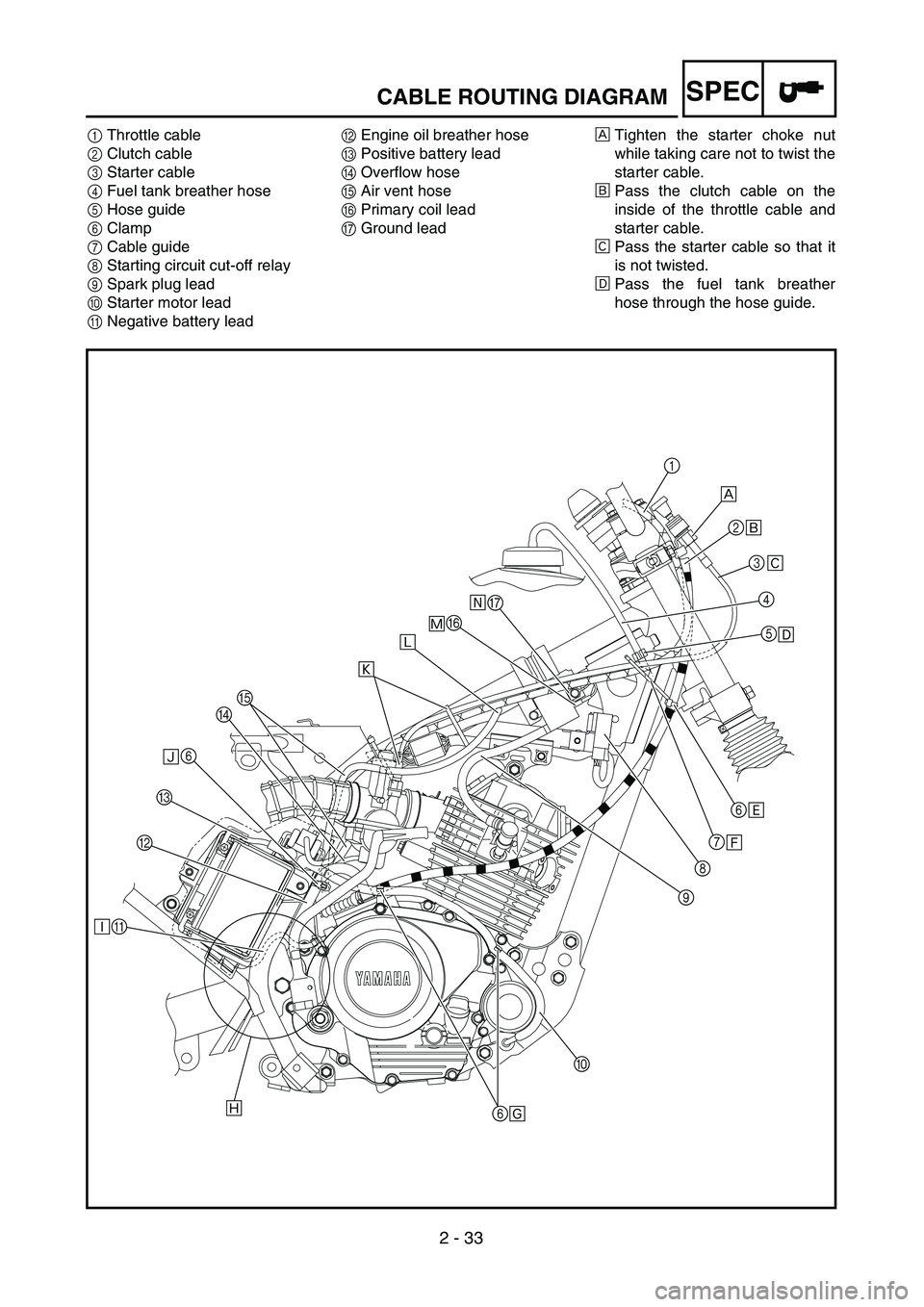
1Throttle cable
2Clutch cable
3Starter cable
4Fuel tank breather hose
5Hose guide
6Clamp
7Cable guide
8Starting circuit cut-off relay
9Spark plug lead
0Starter motor lead
ANegative battery leadBEngine oil breather hose
CPositive battery lead
DOverflow hose
EAir vent hose
FPrimary coil lead
GGround leadÅTighten the starter choke nut
while taking care not to twist the
starter cable.
ıPass the clutch cable on the
inside of the throttle cable and
starter cable.
ÇPass the starter cable so that it
is not twisted.
ÎPass the fuel tank breather
hose through the hose guide.
1
2
3
4
5
6
7
8
9
0
6 ABC6DEFGı
Î
‰
Ï
Ì Ó ÈÔÒ˜ˆ
Ç
Å
CABLE ROUTING DIAGRAM
Page 540 of 610

5 - 58
CHASSWINGARM
EC570000
SWINGARM
Extent of removal:1 Swingarm removal
Extent of removal Order Part name Q’ty Remarks
Preparation for removalSWINGARM REMOVAL
Hold the machine by placing the
suitable stand under the engine.
WARNINGSupport the machine securely so there is nodanger of it falling over.
Rear wheel Refer to “REAR WHEEL AND REAR
BRAKE” section.
1 Drive chain tensioner (upper) 1
2 Drive chain tensioner (lower) 1
3 Bolt (connecting arm-frame) 1
4 Bolt (rear shock absorber-relay arm) 1Hold the swingarm.
5 Pivot shaft 1
6 Swingarm 1
1
Page 542 of 610

5 - 59
CHASSWINGARM
EC578000
SWINGARM DISASSEMBLY
Extent of removal:1 Swingarm disassembly 2 Connecting arm removal and disassembly
3 Relay arm removal and disassembly
Extent of removal Order Part name Q’ty Remarks
SWINGARM DISASSEMBLY
1Drive chain guard 1
2Drive chain support 1
3Drive chain guide 1
4Dust cover 4
5Collar 1
6Connecting arm 1
7Oil seal 2
8Collar 2
9Dust cover 2
0Bushing 1
ARelay arm 1
BDust cover 2
CBushing 1
DSwingarm 1
3
1
2