engine YAMAHA TTR90 2000 Notices Demploi (in French)
[x] Cancel search | Manufacturer: YAMAHA, Model Year: 2000, Model line: TTR90, Model: YAMAHA TTR90 2000Pages: 287, PDF Size: 6.77 MB
Page 28 of 287
1 - 2
GEN
INFO
MACHINE IDENTIFICATION
EC120001
MACHINE IDENTIFICATION
There are two significant reasons for knowing
the serial number of your machine:
1. When ordering parts, you can give the
number to your Yamaha dealer for positive
identification of the model you own.
2. If your machine is stolen, the authorities
will need the number to search for and
identify your machine.
EC121001
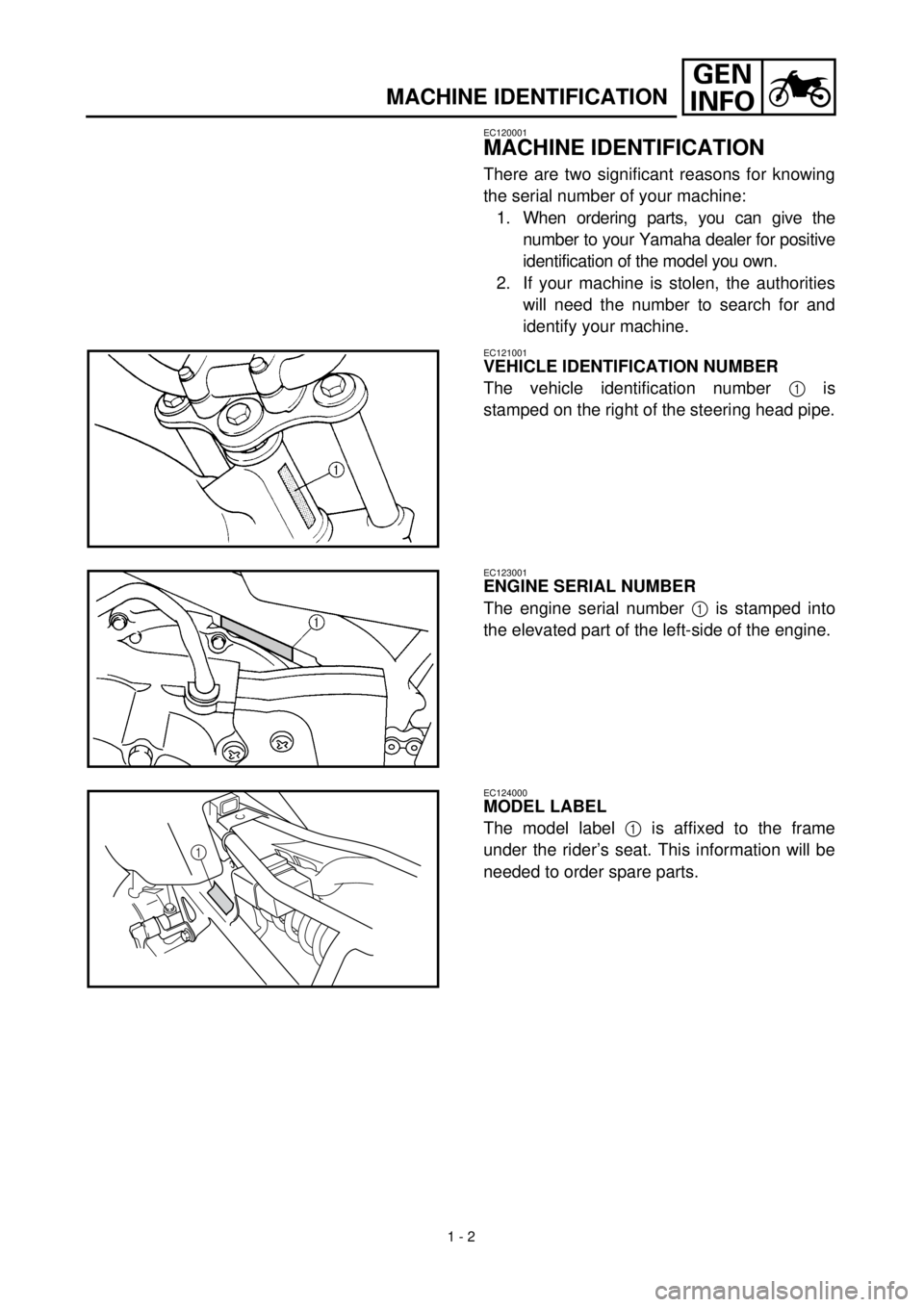
VEHICLE IDENTIFICATION NUMBER
The vehicle identification number
1
is
stamped on the right of the steering head pipe.
EC123001
ENGINE SERIAL NUMBER
The engine serial number
1
is stamped into
the elevated part of the left-side of the engine.
EC124000
MODEL LABEL
The model label
1
is affixed to the frame
under the rider’s seat. This information will be
needed to order spare parts.
1
Page 32 of 287
1 - 4
GEN
INFO
IMPORTANT INFORMATION
EC133000
GASKETS, OIL SEALS AND O-RINGS
1. All gaskets, oil seals, and O-rings should
be replaced when an engine is over-
hauled. All gasket surfaces, oil seal lips,
and O-rings must be cleaned.
2. Properly oil all mating parts and bearings
during reassembly. Apply grease to the
oil seal lips.
EC134000
LOCK WASHERS/PLATES AND COTTER
PINS
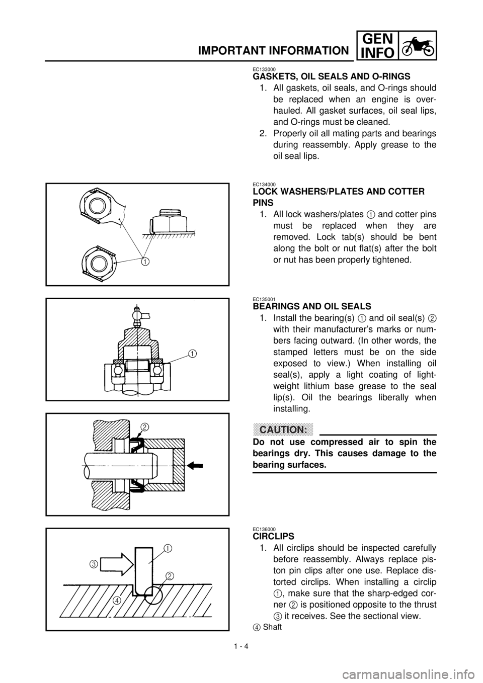
1. All lock washers/plates
1
and cotter pins
must be replaced when they are
removed. Lock tab(s) should be bent
along the bolt or nut flat(s) after the bolt
or nut has been properly tightened.
EC135001
BEARINGS AND OIL SEALS
1. Install the bearing(s)
1
and oil seal(s)
2
with their manufacturer’s marks or num-
bers facing outward. (In other words, the
stamped letters must be on the side
exposed to view.) When installing oil
seal(s), apply a light coating of light-
weight lithium base grease to the seal
lip(s). Oil the bearings liberally when
installing.
CAUTION:
Do not use compressed air to spin the
bearings dry. This causes damage to the
bearing surfaces.
EC136000
CIRCLIPS
1. All circlips should be inspected carefully
before reassembly. Always replace pis-
ton pin clips after one use. Replace dis-
torted circlips. When installing a circlip
1
, make sure that the sharp-edged cor-
ner
2
is positioned opposite to the thrust
3
it receives. See the sectional view.
4
Shaft
Page 36 of 287
GEN
INFO
1 - 6
SPECIAL TOOLS
EC140001
SPECIAL TOOLS
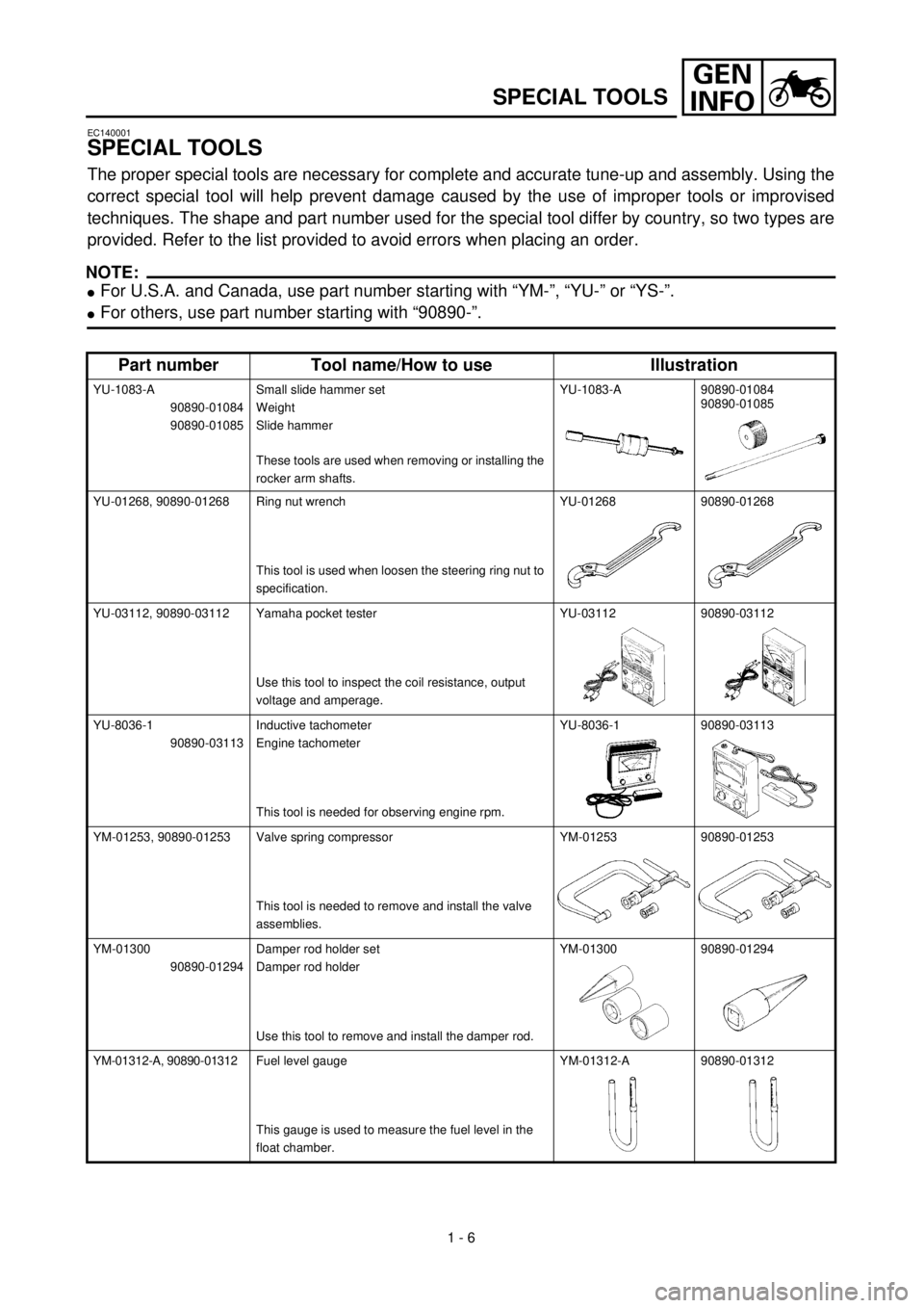
The proper special tools are necessary for complete and accurate tune-up and assembly. Using the
correct special tool will help prevent damage caused by the use of improper tools or improvised
techniques. The shape and part number used for the special tool differ by country, so two types are
provided. Refer to the list provided to avoid errors when placing an order.
NOTE:
l
For U.S.A. and Canada, use part number starting with “YM-”, “YU-” or “YS-”.
lFor others, use part number starting with “90890-”.
Part number Tool name/How to use Illustration
YU-1083-A
90890-01084
90890-01085Small slide hammer set
Weight
Slide hammer
These tools are used when removing or installing the
rocker arm shafts.YU-1083-A 90890-01084
90890-01085
YU-01268, 90890-01268 Ring nut wrench
This tool is used when loosen the steering ring nut to
specification.YU-01268 90890-01268
YU-03112, 90890-03112 Yamaha pocket tester
Use this tool to inspect the coil resistance, output
voltage and amperage.YU-03112 90890-03112
YU-8036-1
90890-03113Inductive tachometer
Engine tachometer
This tool is needed for observing engine rpm.YU-8036-1 90890-03113
YM-01253, 90890-01253 Valve spring compressor
This tool is needed to remove and install the valve
assemblies.YM-01253 90890-01253
YM-01300
90890-01294Damper rod holder set
Damper rod holder
Use this tool to remove and install the damper rod.YM-01300 90890-01294
YM-01312-A, 90890-01312Fuel level gauge
This gauge is used to measure the fuel level in the
float chamber.YM-01312-A 90890-01312
Page 46 of 287
1 - 9
GEN
INFO
CONTROL FUNCTIONS
EC150000
CONTROL FUNCTIONS
EC151000
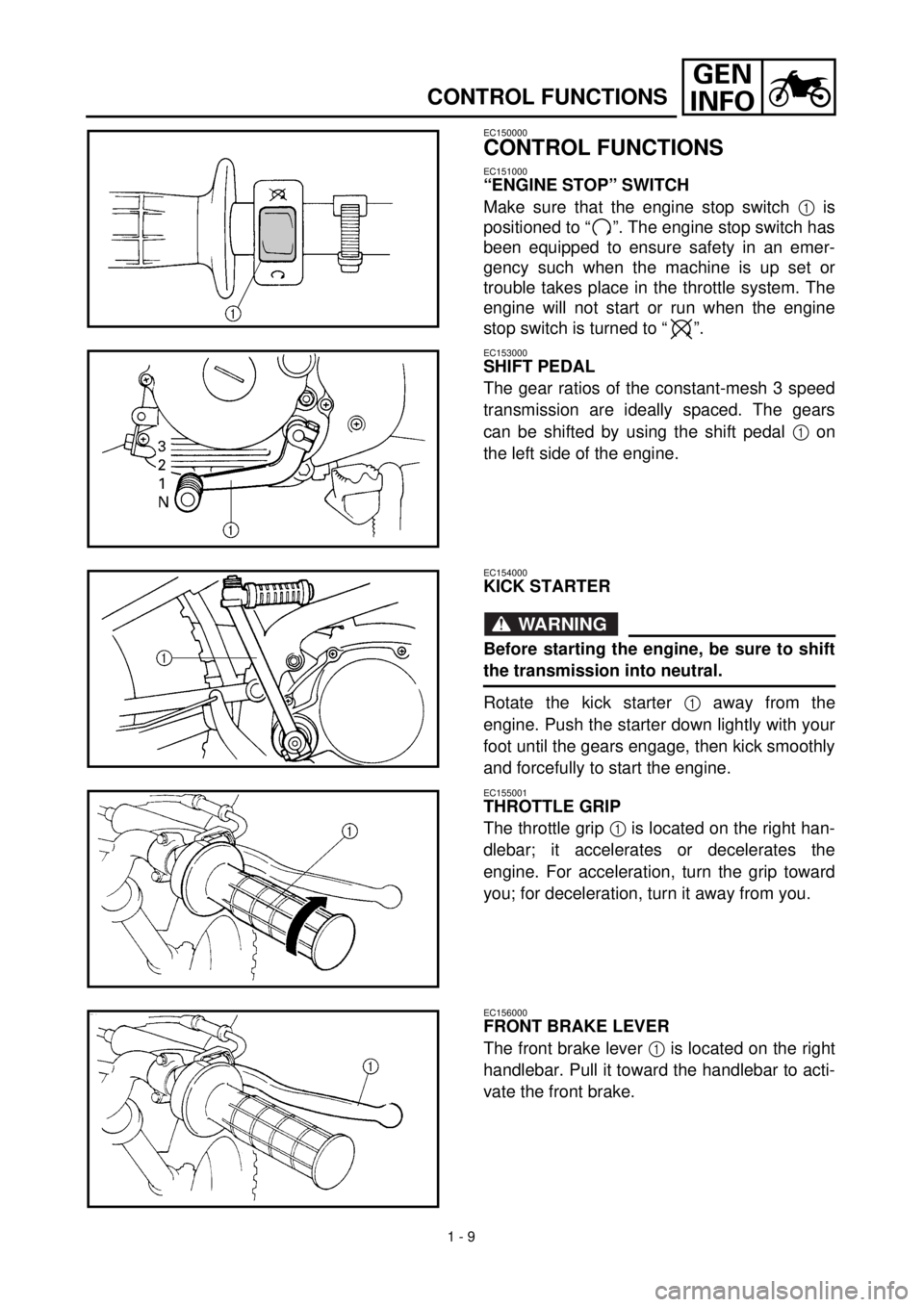
“ENGINE STOP” SWITCH
Make sure that the engine stop switch 1 is
positioned to “ ”. The engine stop switch has
been equipped to ensure safety in an emer-
gency such when the machine is up set or
trouble takes place in the throttle system. The
engine will not start or run when the engine
stop switch is turned to “ ”.
EC153000
SHIFT PEDAL
The gear ratios of the constant-mesh 3 speed
transmission are ideally spaced. The gears
can be shifted by using the shift pedal 1 on
the left side of the engine.
EC154000
KICK STARTER
WARNING
Before starting the engine, be sure to shift
the transmission into neutral.
Rotate the kick starter 1 away from the
engine. Push the starter down lightly with your
foot until the gears engage, then kick smoothly
and forcefully to start the engine.
EC155001
THROTTLE GRIP
The throttle grip 1 is located on the right han-
dlebar; it accelerates or decelerates the
engine. For acceleration, turn the grip toward
you; for deceleration, turn it away from you.
EC156000
FRONT BRAKE LEVER
The front brake lever 1 is located on the right
handlebar. Pull it toward the handlebar to acti-
vate the front brake.
Page 48 of 287
1 - 10
GEN
INFO
CONTROL FUNCTIONS
EC157000
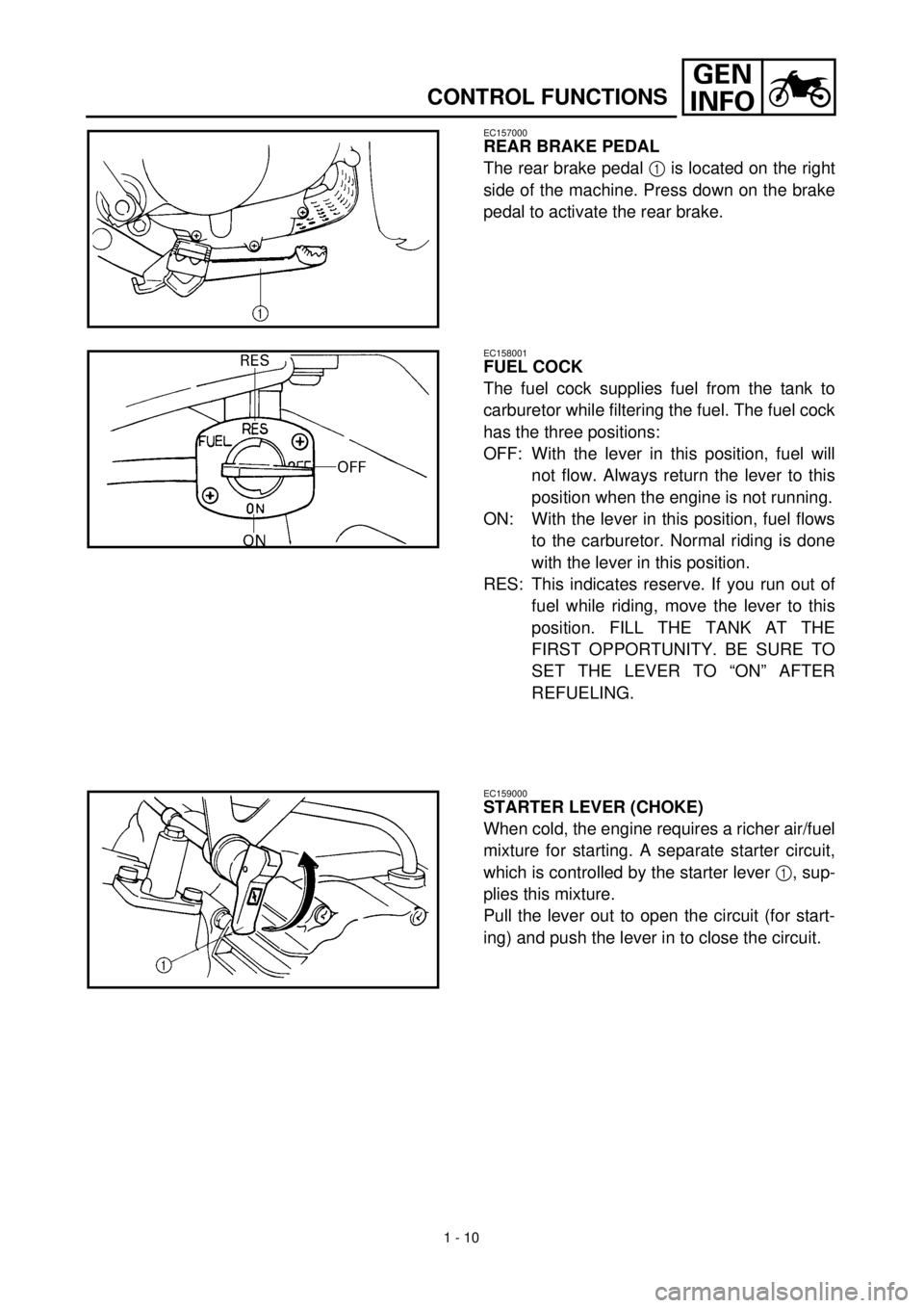
REAR BRAKE PEDAL
The rear brake pedal 1 is located on the right
side of the machine. Press down on the brake
pedal to activate the rear brake.
EC158001
FUEL COCK
The fuel cock supplies fuel from the tank to
carburetor while filtering the fuel. The fuel cock
has the three positions:
OFF: With the lever in this position, fuel will
not flow. Always return the lever to this
position when the engine is not running.
ON: With the lever in this position, fuel flows
to the carburetor. Normal riding is done
with the lever in this position.
RES: This indicates reserve. If you run out of
fuel while riding, move the lever to this
position. FILL THE TANK AT THE
FIRST OPPORTUNITY. BE SURE TO
SET THE LEVER TO “ON” AFTER
REFUELING.
EC159000
STARTER LEVER (CHOKE)
When cold, the engine requires a richer air/fuel
mixture for starting. A separate starter circuit,
which is controlled by the starter lever 1, sup-
plies this mixture.
Pull the lever out to open the circuit (for start-
ing) and push the lever in to close the circuit.
Page 50 of 287
1 - 11
GEN
INFO
CONTROL FUNCTIONS/FUEL
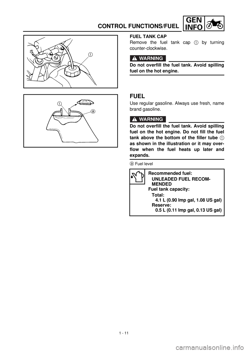
FUEL TANK CAP
Remove the fuel tank cap 1 by turning
counter-clockwise.
WARNING
Do not overfill the fuel tank. Avoid spilling
fuel on the hot engine.
FUEL
Use regular gasoline. Always use fresh, name
brand gasoline.
WARNING
Do not overfill the fuel tank. Avoid spilling
fuel on the hot engine. Do not fill the fuel
tank above the bottom of the filler tube 1
as shown in the illustration or it may over-
flow when the fuel heats up later and
expands.
aFuel level
Recommended fuel:
UNLEADED FUEL RECOM-
MENDED
Fuel tank capacity:
Total:
4.1 L (0.90 lmp gal, 1.08 US gal)
Reserve:
0.5 L (0.11 lmp gal, 0.13 US gal)
Page 52 of 287
GEN
INFO
1 - 12
STARTING AND OPERATION
STARTING AND OPERATION
CAUTION:
Prior to operating the machine, perform
steps listed in pre-operation check list.
WARNING
Never start your engine or let it run for any
length of time in a closed area. The exhaust
fumes are poisonous and can cause loss of
consciousness and death within a short
time. Always operate your machine in an
area with adequate ventilation.
STARTING A COLD ENGINE
WARNING
Before starting the engine, be sure to shift
the transmission into neutral.
1. Turn the fuel cock to “ON”.
2. Operate the starter (choke) and com-
pletely close the throttle grip.
3. Slide the “ENGINE STOP” switch to the
“”.
4. Kick the kick starter with full strength to
start the engine.
5. After the engine starts, warm up for one
or two minutes. Make sure the stater
(choke) is returned to the original position
before riding.
STARTING A WARM ENGINE
To start a warm engine, refer to the “Starting a
cold engine” section. The starter (choke)
should not be used. The throttle should be
opened slightly.
CAUTION:
See “Break-in Section” prior to operating
engine for the first time.WARMING UP
To get maximum engine life, always “warm-up”
the engine before starting off. Never acceler-
ate hard with a cold engine! To see whether or
not the engine is warm, see if it responds to
throttle normally with the stater (choke) turned
off.
WARNING
Before starting off, be sure to turn up or
remove the side stand.
Failure to retract the side stand completely
can result in a serious accident when you
try to turn a corner.
ENGINE BREAK-IN
1. Prior to starting, fill fuel tank with gasoline
and oil tank with specified oil.
2. Allow engine to warm up. Check engine
idling speed. Check operating controls
and engine stop switch operation.
3. Operate machine in lower gears at mod-
erate throttle setting for 3 ~ 5 minutes.
Check spark plug condition.
4. Allow engine to cool. Repeat procedure,
running for 5 minutes. Very briefly, shift to
higher gears and check full throttle
response. Check spark plug condition.
5. Allow engine to cool. Repeat procedure,
running for 5 minutes. Full throttle and
higher gears may be used, but avoid sus-
tained full throttle operation. Check spark
plug condition.
6. Allow engine to cool. Remove top end and
inspect. Remove “high” spots on piston
with No.600 grit, wet sandpaper.
Clean, and carefully reassemble.
7. Check entire unit for loose or misadjusted
fittings/controls/fasteners.
8. Re-start engine and check through entire
operating range thoroughly. Stop. Check
spark plug condition. Re-start. After 10 ~
15 minutes operation, machine is ready
to ride.
CAUTION:
After the break-in period, check every fit-
ting and fastener for looseness.
If any loose is found, retighten it securely.
Page 56 of 287
SPEC
2 - 1
EC200000
SPECIFICATIONS
EC211000
GENERAL SPECIFICATIONS
Model name: TTR90M
Model code number: 5HN1 (USA-except for California)
5HN2 (USA-for California)
5HN3 (Europe, Oceania)
5HN4 (CDN)
Dimensions:
Overall length 1,525 mm (57.0 in)
Overall width 605 mm (23.8 in)
Overall height 865 mm (34.1 in)
Seat height 625 mm (24.6 in)
Wheelbase 1,040 mm (40.9 in)
Minimum ground clearance 160 mm (6.3 in)
Minimum turning radius 1,328 mm (52.3 in)
Basic weight:
With oil and full fuel tank 64 kg (141 lb)
Engine:
Engine type Air cooled 4-stroke, SOHC
Cylinder arrangement Single cylinder, forward inclined
Displacement 89 cm
3
(5.43 cu.in)
Bore
´
stroke 47.0
´
51.8 mm (1.85
´
2.04 in)
Compression ratio 8.5 : 1
Compression pressure (STD) 1,000 kPa (10 kg/cm
2
, 145 psi) at 1,000 r/min
Starting system Kick starter
Lubrication system: Wet sump
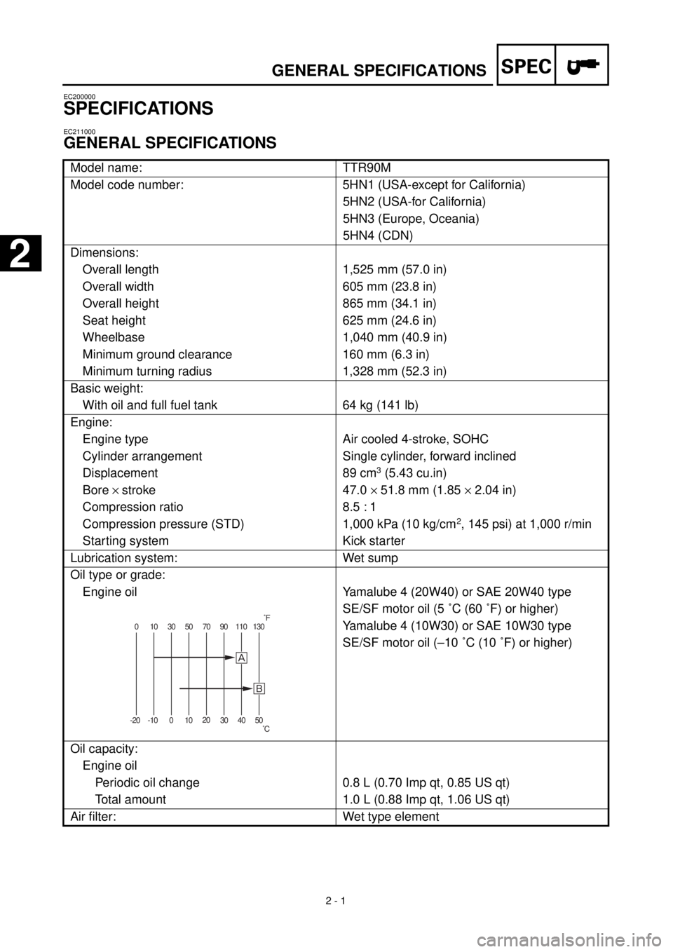
Oil type or grade:
Engine oil
Yamalube 4 (20W40) or SAE 20W40 type
SE/SF motor oil (5 ˚C (60 ˚F) or higher)
Yamalube 4 (10W30) or SAE 10W30 type
SE/SF motor oil (–10 ˚C (10 ˚F) or higher)
Oil capacity:
Engine oil
Periodic oil change 0.8 L (0.70 Imp qt, 0.85 US qt)
Total amount 1.0 L (0.88 Imp qt, 1.06 US qt)
Air filter: Wet type element
0 10 30 50 70 90 110 130
-20 -10 01020
30 40 50
õ
˚F
˚C
GENERAL SPECIFICATIONS
2
Page 59 of 287
SPEC
2 - 4
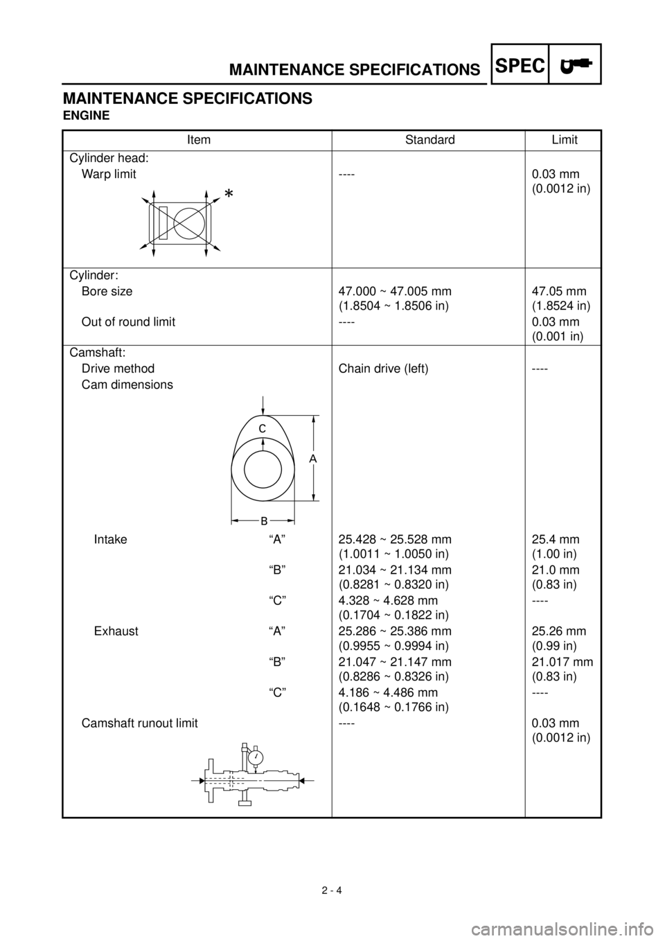
MAINTENANCE SPECIFICATIONS
ENGINE
Item Standard Limit
Cylinder head:
Warp limit ---- 0.03 mm
(0.0012 in)
Cylinder:
Bore size 47.000 ~ 47.005 mm
(1.8504 ~ 1.8506 in)47.05 mm
(1.8524 in)
Out of round limit ---- 0.03 mm
(0.001 in)
Camshaft:
Drive method Chain drive (left) ----
Cam dimensions
Intake “A” 25.428 ~ 25.528 mm
(1.0011 ~ 1.0050 in)25.4 mm
(1.00 in)
“B” 21.034 ~ 21.134 mm
(0.8281 ~ 0.8320 in)21.0 mm
(0.83 in)
“C” 4.328 ~ 4.628 mm
(0.1704 ~ 0.1822 in)----
Exhaust “A” 25.286 ~ 25.386 mm
(0.9955 ~ 0.9994 in)25.26 mm
(0.99 in)
“B” 21.047 ~ 21.147 mm
(0.8286 ~ 0.8326 in)21.017 mm
(0.83 in)
“C” 4.186 ~ 4.486 mm
(0.1648 ~ 0.1766 in)----
Camshaft runout limit ---- 0.03 mm
(0.0012 in)
C
A
B
MAINTENANCE SPECIFICATIONS
Page 63 of 287
SPEC
2 - 8
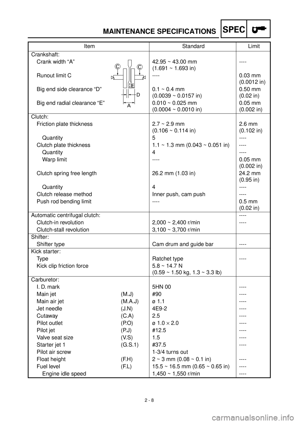
Crankshaft:
Crank width “A” 42.95 ~ 43.00 mm
(1.691 ~ 1.693 in)----
Runout limit C ---- 0.03 mm
(0.0012 in)
Big end side clearance “D” 0.1 ~ 0.4 mm
(0.0039 ~ 0.0157 in)0.50 mm
(0.02 in)
Big end radial clearance “E” 0.010 ~ 0.025 mm
(0.0004 ~ 0.0010 in)0.05 mm
(0.002 in)
Clutch:
Friction plate thickness 2.7 ~ 2.9 mm
(0.106 ~ 0.114 in)2.6 mm
(0.102 in)
Quantity 5 ----
Clutch plate thickness 1.1 ~ 1.3 mm (0.043 ~ 0.051 in) ----
Quantity 4 ----
Warp limit ---- 0.05 mm
(0.002 in)
Clutch spring free length 26.2 mm (1.03 in) 24.2 mm
(0.95 in)
Quantity 4 ----
Clutch release method Inner push, cam push ----
Push rod bending limit ---- 0.5 mm
(0.02 in)
Automatic centrifugal clutch: ----
Clutch-in revolution 2,000 ~ 2,400 r/min ----
Clutch-stall revolution 3,100 ~ 3,700 r/min
Shifter:
Shifter type Cam drum and guide bar ----
Kick starter:
Type Ratchet type ----
Kick clip friction force 5.8 ~ 14.7 N
(0.59 ~ 1.50 kg, 1.3 ~ 3.3 lb)
Carburetor:
I. D. mark 5HN 00 ----
Main jet (M.J) #90 ----
Main air jet (M.A.J) ø 1.1 ----
Jet needle (J.N) 4E9-2 ----
Cutaway (C.A) 2.5 ----
Pilot outlet (P.O) ø 1.0
´
2.0 ----
Pilot jet (P.J) #12.5 ----
Valve seat size (V.S) 1.5 ----
Starter jet 1 (G.S.1) #37.5 ----
Pilot air screw 1-3/4 turns out
Float height (F.H) 2 ~ 3 mm (0.08 ~ 0.1 in) ----
Fuel level (F.L) 15.5 ~ 16.5 mm (0.65 ~ 0.65 in) ----
Engine idle speed 1,450 ~ 1,550 r/min ----Item Standard Limit
MAINTENANCE SPECIFICATIONS
CC
D
A
E