service YAMAHA VX110 2005 Service Manual
[x] Cancel search | Manufacturer: YAMAHA, Model Year: 2005, Model line: VX110, Model: YAMAHA VX110 2005Pages: 347, PDF Size: 14.17 MB
Page 235 of 347

7-8
E
–+ELECECM AND RECTIFIER/REGULATOR
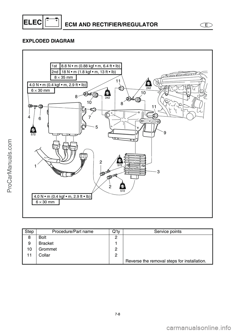
EXPLODED DIAGRAM
Step Procedure/Part name Q’ty Service points
8Bolt 2
9Bracket 1
10 Grommet 2
11 Collar 2
Reverse the removal steps for installation.
2nd 18 N • m (1.8 kgf • m, 13 ft • Ib) 1st 8.8 N • m (0.88 kgf • m, 6.4 ft • Ib)
8 × 35 mm
6 × 30 mm
4.0 N • m (0.4 kgf • m, 2.9 ft • Ib)
6 × 30 mm
4.0 N • m (0.4 kgf • m, 2.9 ft • Ib)
LT
572
LT
LT
242
LT
LT
242
LT
LT
572
LT
LT
572
LT
4
6
5
12
239 10
8 10 8
11
11
7
ProCarManuals.com
Page 241 of 347

7-14
E
–+ELECIGNITION SYSTEM
IGNITION SPARK
WARNING
When checking the spark gap, do not
touch any of the connections of the spark
checker/ignition tester lead wires.
When performing the spark gap test, take
special care not to let sparks leak out of
the removed spark plug cap.
When performing the spark gap check,
keep flammable gas or liquids away,
since this test can produce sparks.
1. Check:
Ignition spark
Weak →
Check the ECM output peak
voltage.
Check the ignition coil for resistance.
Checking steps:
Connect the spark plug cap to the special
service tool.
Spark checker:
YM-34487
Ignition tester:
90890-06754
Crank the engine and observe the igni-
tion system spark through the discharge
window.
OK
ProCarManuals.com
Page 266 of 347

7-39
E
–+ELECSTARTER MOTOR
STARTER MOTOR
EXPLODED DIAGRAM
REMOVAL AND INSTALLATION CHART
Step Procedure/Part name Q’ty Service points
STARTER MOTOR
DISASSEMBLYFollow the left “Step” for disassembly.
Starter motor Refer to “GENERATOR AND STARTER
MOTOR” in Chapter 5.
1 O-ring 1
2Bolt 2
3 Starter motor front cover assembly 1
4 O-ring 2
5 Washer set 1
6 Armature assembly 1
AA
5 × 114 mm
6.4 N m (0.64 kgf m, 4.6 ft Ib)5
72
9
44 6
5
3
1
8
8.8 N m (0.88 kgf m, 6.4 ft Ib)
Not reusable
Not reusable
ProCarManuals.com
Page 267 of 347

7-40
E
–+ELECSTARTER MOTOR
EXPLODED DIAGRAM
Step Procedure/Part name Q’ty Service points
7 Starter motor rear cover 1
8 Brush holder assembly 1
9 Starter motor yoke 1
Reverse the disassembly steps for
assembly.
AA
5 × 114 mm
6.4 N m (0.64 kgf m, 4.6 ft Ib)5
72
9
44 6
5
3
1
8
8.8 N m (0.88 kgf m, 6.4 ft Ib)
ProCarManuals.com
Page 268 of 347

7-41
E
–+ELECSTARTER MOTOR
SERVICE POINTS
Armature inspection
1. Inspect:
Armature shaft 1
Damage/wear → Replace.
1
2. Inspect:
Commutator
Dirt → Clean with 600-grit sandpaper.
3. Measure:
Commutator diameter
Below specification → Replace.
Commutator diameter:
28.0 mm (1.10 in)
Limit:
27.0 mm (1.06 in)
4. Check:
Commutator undercut
Contaminants → Clean.
NOTE:
Remove all mica and metal particles with com-
pressed air.
5. Measure:
Commutator undercut
Below specification → Replace.
Commutator undercut:
0.7 mm (0.03 in)
Limit:
0.2 mm (0.01 in)
ProCarManuals.com
Page 292 of 347

E
HULL
HOOD
CHAPTER 8
HULL AND HOOD
HANDLEBAR .................................................................................................. 8-1
EXPLODED DIAGRAM ............................................................................. 8-1
REMOVAL AND INSTALLATION CHART ................................................ 8-1
SERVICE POINTS .................................................................................... 8-6
Handlebar inspection .......................................................................... 8-6
Handlebar switch inspection ............................................................... 8-6
Handlebar assembly installation ......................................................... 8-6
FRONT HOOD ................................................................................................. 8-8
EXPLODED DIAGRAM ............................................................................. 8-8
REMOVAL AND INSTALLATION CHART ................................................ 8-8
SERVICE POINTS .................................................................................. 8-10
Rivet Installation ................................................................................ 8-10
ENGINE HATCH COVER .............................................................................. 8-11
EXPLODED DIAGRAM ........................................................................... 8-11
REMOVAL AND INSTALLATION CHART .............................................. 8-11
SERVICE POINTS .................................................................................. 8-13
Damper stopper inspection (Deluxe model only) .............................. 8-13
EXPLODED DIAGRAM ........................................................................... 8-14
REMOVAL AND INSTALLATION CHART .............................................. 8-14
SERVICE POINTS .................................................................................. 8-15
Glove compartment assembly installation......................................... 8-15
SHIFT LEVER (DELUXE MODEL ONLY) ..................................................... 8-16
EXPLODED DIAGRAM ........................................................................... 8-16
REMOVAL AND INSTALLATION CHART .............................................. 8-16
HOSES .......................................................................................................... 8-17
EXPLODED DIAGRAM ........................................................................... 8-17
REMOVAL AND INSTALLATION CHART .............................................. 8-17
SERVICE POINTS .................................................................................. 8-19
Cooling water pilot outlet installation ................................................. 8-19
Grommet installation ......................................................................... 8-19
Ventilation hose assembly installation .............................................. 8-19
STEERING COLUMN .................................................................................... 8-20
EXPLODED DIAGRAM ........................................................................... 8-20
REMOVAL AND INSTALLATION CHART .............................................. 8-20
SERVICE POINTS .................................................................................. 8-22
Steering column inspection ............................................................... 8-22
ProCarManuals.com
Page 293 of 347

E
HULL
HOOD
1
2
3
4
5
6
7
8
9
REMOTE CONTROL CABLES AND SPEED SENSOR LEAD .................... 8-23
EXPLODED DIAGRAM ........................................................................... 8-23
REMOVAL AND INSTALLATION CHART .............................................. 8-23
SERVICE POINTS .................................................................................. 8-26
Remote control cables inspection ..................................................... 8-26
Steering cable (jet pump end) installation ......................................... 8-26
Steering cable stopper installation .................................................... 8-26
Shift cable (jet pump end) installation (Deluxe model only) .............. 8-27
Shift cable (shift lever end) installation (Deluxe model only)............. 8-27
Remote control cables adjustment .................................................... 8-27
SEAT AND HAND GRIP................................................................................ 8-28
EXPLODED DIAGRAM ........................................................................... 8-28
REMOVAL AND INSTALLATION CHART .............................................. 8-28
SERVICE POINTS .................................................................................. 8-30
Seat lock assembly inspection .......................................................... 8-30
EXHAUST SYSTEM ...................................................................................... 8-31
EXPLODED DIAGRAM ........................................................................... 8-31
REMOVAL AND INSTALLATION CHART .............................................. 8-31
SERVICE POINTS .................................................................................. 8-34
Exhaust system inspection................................................................ 8-34
Exhaust component parts sub-assembly .......................................... 8-34
Exhaust system installation ............................................................... 8-35
DECK AND HULL.......................................................................................... 8-36
EXPLODED DIAGRAM ........................................................................... 8-36
REMOVAL AND INSTALLATION CHART .............................................. 8-36
ENGINE MOUNT ........................................................................................... 8-38
EXPLODED DIAGRAM ........................................................................... 8-38
REMOVAL AND INSTALLATION CHART .............................................. 8-38
ProCarManuals.com
Page 294 of 347

8-1
E
HULL
HOODHANDLEBAR
HANDLEBAR
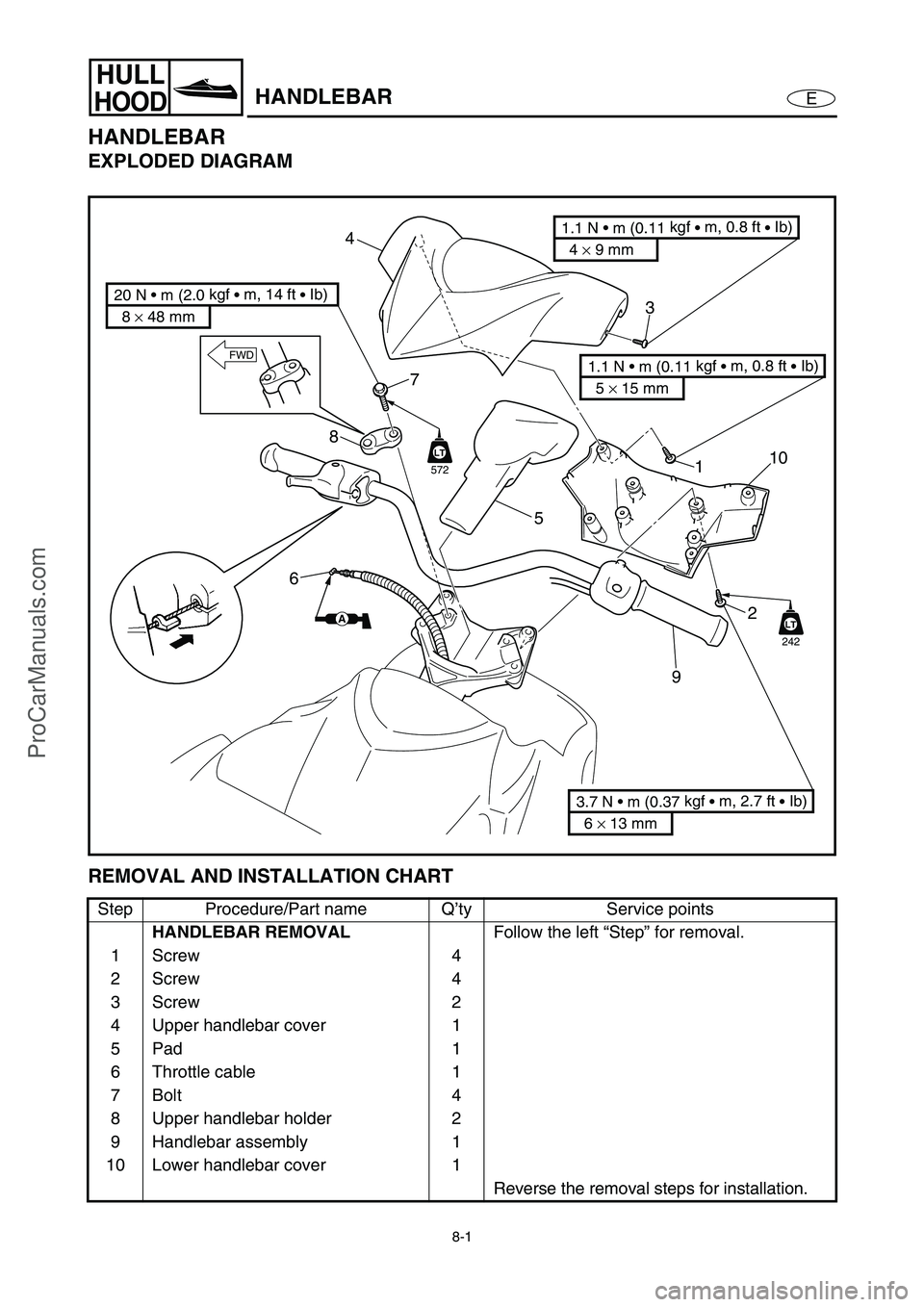
EXPLODED DIAGRAM
REMOVAL AND INSTALLATION CHART
Step Procedure/Part name Q’ty Service points
HANDLEBAR REMOVAL
Follow the left “Step” for removal.
1Screw 4
2Screw 4
3Screw 2
4 Upper handlebar cover 1
5Pad 1
6 Throttle cable 1
7Bolt 4
8 Upper handlebar holder 2
9 Handlebar assembly 1
10 Lower handlebar cover 1
Reverse the removal steps for installation.
LT
242
8 × 48 mm
20 N • m (2.0 kgf
• m, 14 ft
• Ib)
6 × 13 mm
3.7 N • m (0.37 kgf
• m, 2.7 ft
• Ib)
4 × 9 mm
1.1 N • m (0.11 kgf
• m, 0.8 ft
• Ib)
5 × 15 mm
1.1 N • m (0.11 kgf
• m, 0.8 ft
• Ib)
87
1
2
910
5
4
3
6
FWD
AA
LT
572
ProCarManuals.com
Page 295 of 347

8-2
E
HULL
HOODHANDLEBAR
EXPLODED DIAGRAM
REMOVAL AND INSTALLATION CHART
Step Procedure/Part name Q’ty Service points
HANDLEBAR REMOVAL
Follow the left “Step” for removal.
1 Handlebar switch coupler 2
2 Plastic tie 1
NOTE:
Fasten the buzzer lead, steering sensor
lead, start switch lead, engine shut-off
switch lead, and multifunction meter lead
with a plastic tie.
3 Corrugated tube 1
4 Grommet 1
4 5
3
4
3
7
2
FWD
6
11
6
ProCarManuals.com
Page 296 of 347

8-3
E
HULL
HOODHANDLEBAR
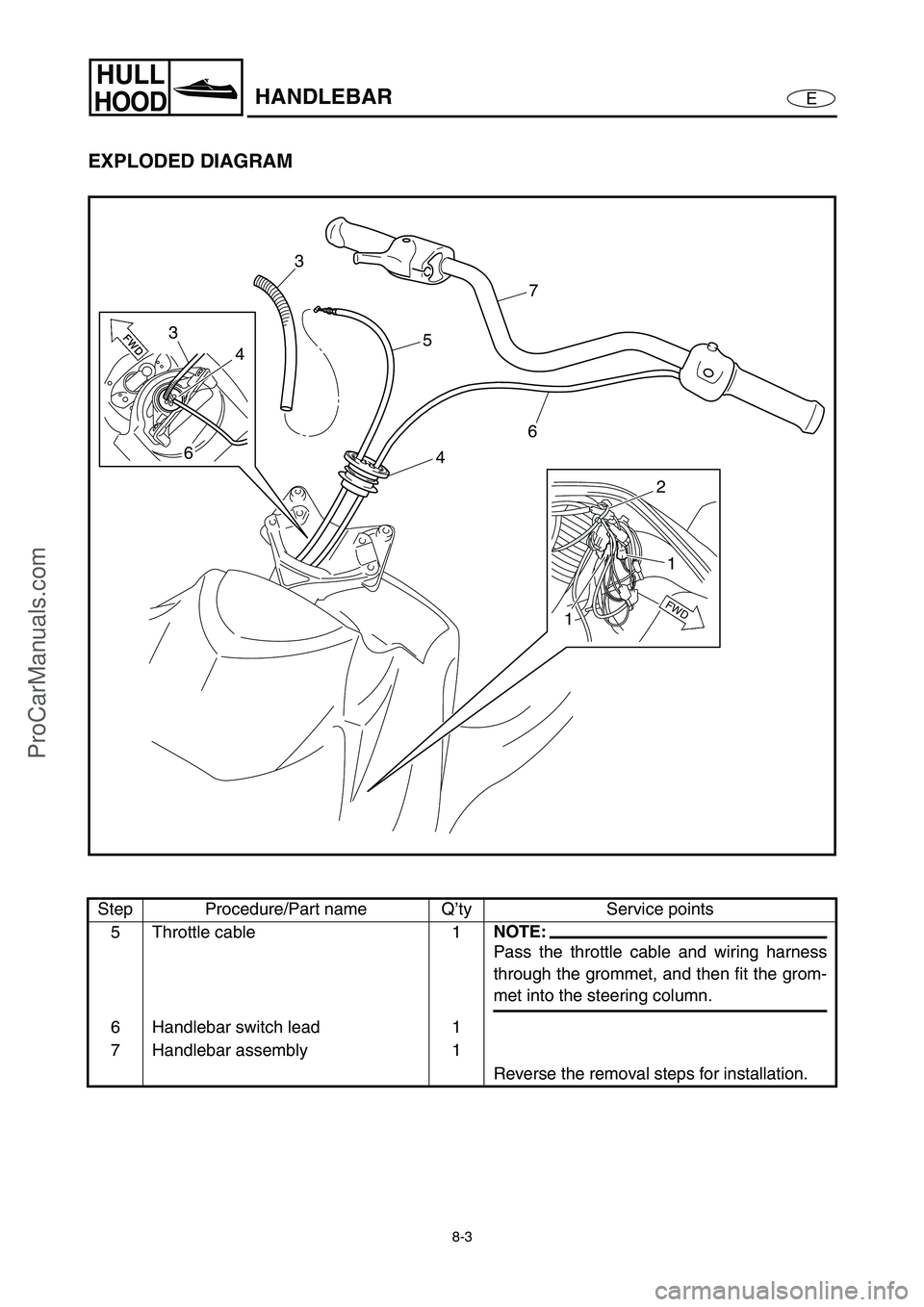
EXPLODED DIAGRAM
Step Procedure/Part name Q’ty Service points
5 Throttle cable 1
NOTE:
Pass the throttle cable and wiring harness
through the grommet, and then fit the grom-
met into the steering column.
6 Handlebar switch lead 1
7 Handlebar assembly 1
Reverse the removal steps for installation.
4 5
3
4
3
7
2
FWD
6
11
6
ProCarManuals.com