check engine YAMAHA WOLVERINE 2015 Owner's Manual
[x] Cancel search | Manufacturer: YAMAHA, Model Year: 2015, Model line: WOLVERINE, Model: YAMAHA WOLVERINE 2015Pages: 186, PDF Size: 4.22 MB
Page 136 of 186
8-24
8
8. Check for oil leakage. If oil leakage isfound, check for the cause.EBU33660CoolantThe coolant level should be checked before
each ride. In addition, the coolant must be
changed at the intervals specified in the peri-
odic maintenance and lubrication chart.
Checking the coolant level1. Park the vehicle on a level surface.
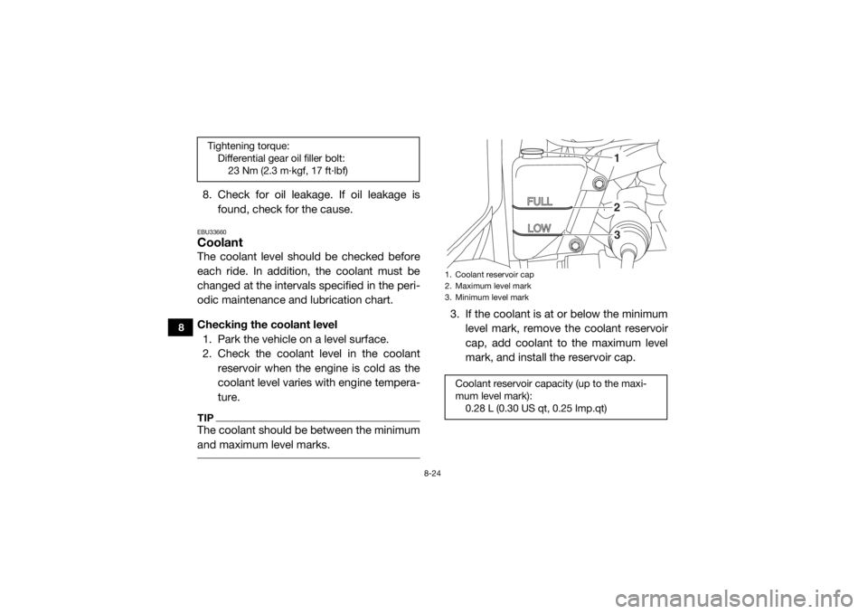
2. Check the coolant level in the coolant reservoir when the engine is cold as the
coolant level varies with engine tempera-
ture.TIPThe coolant should be between the minimum
and maximum level marks.
3. If the coolant is at or below the minimum
level mark, remove the coolant reservoir
cap, add coolant to the maximum level
mark, and install the reservoir cap.
Tightening torque:Differential gear oil filler bolt:23 Nm (2.3 m·kgf, 17 ft·lbf)
1. Coolant reservoir cap
2. Maximum level mark
3. Minimum level markCoolant reservoir capacity (up to the maxi-
mum level mark):0.28 L (0.30 US qt, 0.25 Imp.qt)
123
U2MB7AE0.book Page 24 Thursday, January 29, 2015 3:42 PM
Page 141 of 186
8-29
8
22. Stop the engine and allow it to cool. If thecoolant level has dropped after the en-
gine has cooled, add sufficient coolant
until it reaches the top of the radiator, and
then install the radiator cap.
23. Check the coolant level in the reservoir. If necessary, remove the coolant reservoir
cap, add coolant to the maximum level
mark, and then install the cap.
24. Start the engine, and then check for cool- ant leakage.TIPIf any leakage is found, have a Yamaha dealer
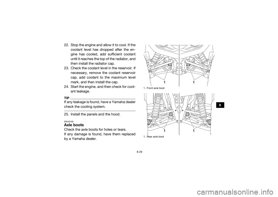
check the cooling system. 25. Install the panels and the hood.EBU32400Axle bootsCheck the axle boots for holes or tears.
If any damage is found, have them replaced
by a Yamaha dealer.
1. Front axle boot
1. Rear axle boot
1
1
1
1
U2MB7AE0.book Page 29 Thursday, January 29, 2015 3:42 PM
Page 144 of 186
8-32
8
EBU33580Cleaning the air filter elementThe air filter element should be cleaned every
20–40 hours. It should be cleaned and lubri-
cated more often if the vehicle is operated in
extremely dusty areas. Each time air filter ele-
ment maintenance is performed, check the air
inlet to the air filter case for obstructions.
Check the air filter element rubber joint to the
throttle body and manifold fittings for an air-
tight seal. Tighten all fittings securely to avoid
the possibility of unfiltered air entering the en-
gine.NOTICEECB02270Never operate the engine with the air filter
element removed. Doing so would allow
unfiltered air to enter, causing rapid en-
gine wear and possible engine damage.
Additionally, the fuel injection system
would be affected, resulting in poor engine
performance and possible overheating.
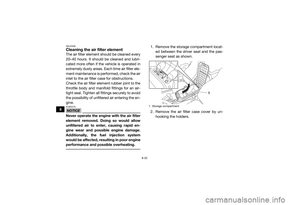
1. Remove the storage compartment locat-ed between the driver seat and the pas-
senger seat as shown.
2. Remove the air filter case cover by un- hooking the holders.1. Storage compartment
1
U2MB7AE0.book Page 32 Thursday, January 29, 2015 3:42 PM
Page 148 of 186
8-36
8
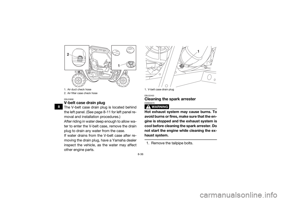
EBU33690V-belt case drain plugThe V-belt case drain plug is located behind
the left panel. (See page 8-11 for left panel re-
moval and installation procedures.)
After riding in water deep enough to allow wa-
ter to enter the V-belt case, remove the drain
plug to drain any water from the case.
If water drains from the V-belt case after re-
moving the drain plug, have a Yamaha dealer
inspect the vehicle, as the water may affect
other engine parts.
EBU32450Cleaning the spark arrester
WARNING
EWB03370Hot exhaust system may cause burns. To
avoid burns or fires, make sure that the en-
gine is stopped and the exhaust system is
cool before cleaning the spark arrester. Do
not start the engine while cleaning the ex-
haust system. 1. Remove the tailpipe bolts.
1. Air duct check hose
2. Air filter case check hose2
1
1. V-belt case drain plug
1
U2MB7AE0.book Page 36 Thursday, January 29, 2015 3:42 PM
Page 150 of 186
8-38
8
EBU32460Valve clearanceThe correct valve clearance changes with
use, resulting in improper fuel/air supply or
engine noise. To prevent this, the valve clear-
ance must be adjusted regularly. This adjust-
ment however, should be left to a
professional Yamaha service technician.EBU32470BrakesReplacement of brake components requires
professional knowledge. Brake service
should be performed by a Yamaha dealer.
WARNING
EWB02572Operating with improperly serviced or ad-
justed brakes could lead to a loss in brak-
ing ability and an accident.
EBU32480Checking the front and rear brake padsEach brake pad is provided with wear indica-
tor grooves, which allow you to check the
brake pad wear without having to disassem-
ble the brake. To check the brake pad wear,
check the wear indicator grooves. If a brake
pad has worn to the point that the wear indi-
cator grooves have almost disappeared, have
a Yamaha dealer replace the brake pads as a
set.
The wheels need to be removed to check the
brake pads. (See pages 8-44, 8-46 for wheel
removal and installation procedures.)
U2MB7AE0.book Page 38 Thursday, January 29, 2015 3:42 PM
Page 171 of 186
8-59
8
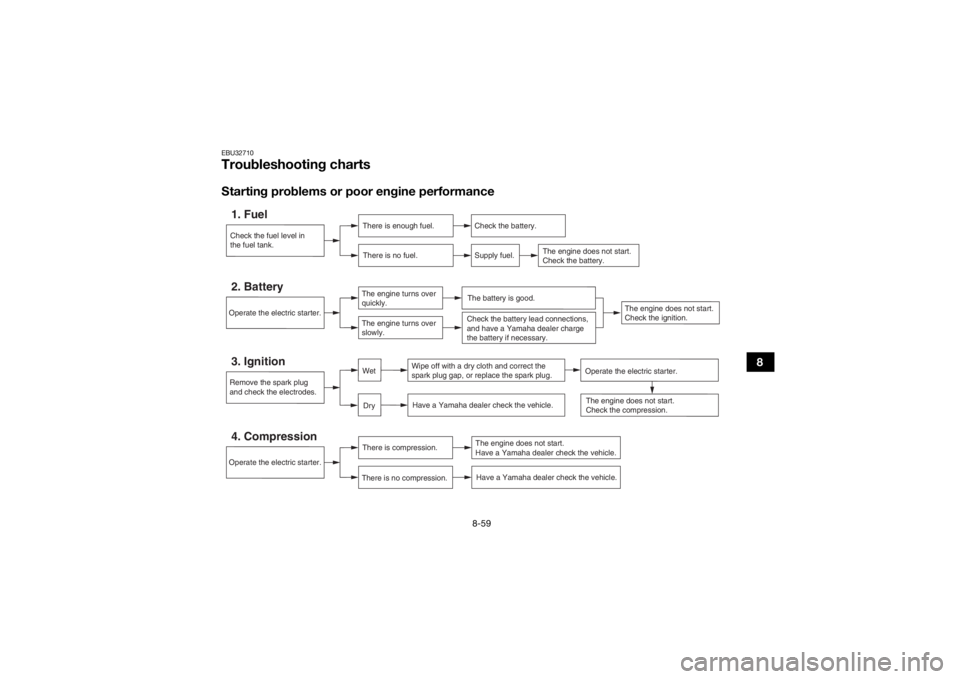
EBU32710Troubleshooting chartsStarting problems or poor engine performanceCheck the fuel level in
the fuel tank.1. Fuel
There is enough fuel.
There is no fuel.
Check the battery.
Supply fuel.
The engine does not start.
Check the battery.
Operate the electric starter.4. Compression
There is compression.
There is no compression.
The engine does not start.
Have a Yamaha dealer check the vehicle.Have a Yamaha dealer check the vehicle.
Remove the spark plug
and check the electrodes.3. Ignition
Wipe off with a dry cloth and correct the
spark plug gap, or replace the spark plug. Have a Yamaha dealer check the vehicle.
The engine does not start.
Check the compression.
Operate the electric starter.2. Battery
The engine turns over
quickly.
The engine turns over
slowly.
The battery is good.
DryWet
Operate the electric starter.
Check the battery lead connections,
and have a Yamaha dealer charge
the battery if necessary.
The engine does not start.
Check the ignition.
U2MB7AE0.book Page 59 Thursday, January 29, 2015 3:42 PM
Page 172 of 186
8-60
8
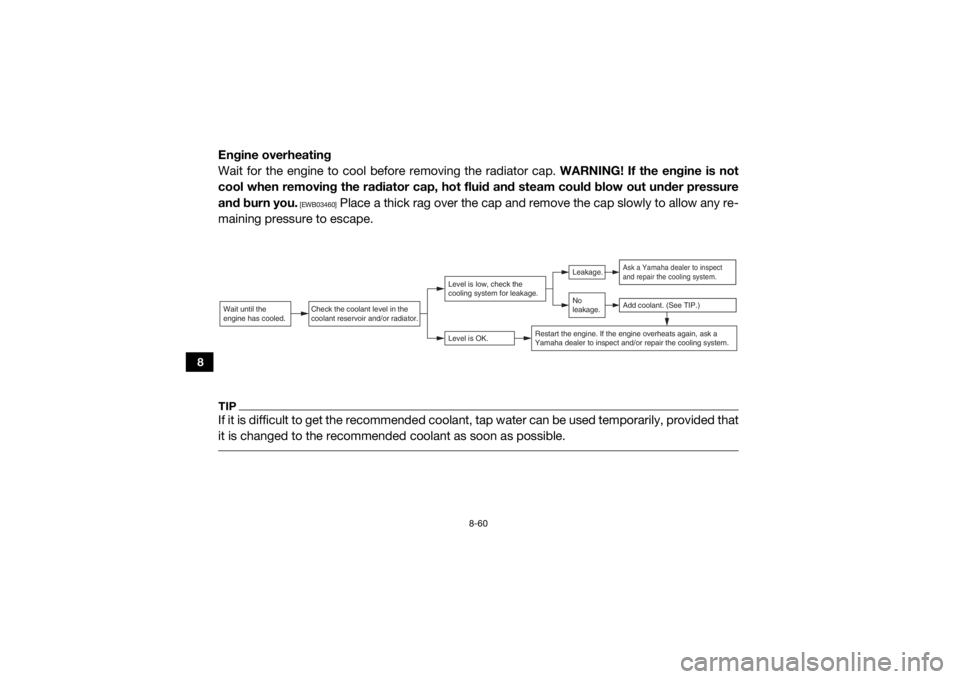
Engine overheating
Wait for the engine to cool before removing the radiator cap. WARNING! If the engine is not
cool when removing the radiator cap, hot fluid and steam could blow out under pressure
and burn you.
[EWB03460]
Place a thick rag over the cap and remove the cap slowly to allow any re-
maining pressure to escape.
TIPIf it is difficult to get the recommended coolant, tap water can be used temporarily, provided that
it is changed to the recommende d coolant as soon as possible. Wait until the
engine has cooled.
Check the coolant level in the
coolant reservoir and/or radiator.
Level is OK.Level is low, check the
cooling system for leakage.
No
leakage.Leakage.
Ask a Yamaha dealer to inspect
and repair the cooling system.Add coolant. (See TIP.)
Restart the engine. If the engine overheats again, ask a
Yamaha dealer to inspect and/or repair the cooling system.
U2MB7AE0.book Page 60 Thursday, January 29, 2015 3:42 PM
Page 183 of 186

12-1
12
INDEX
AAccelerator pedal ......................................................... 4-12
Accelerator pedal, Pre-operation check ........................ 5-7
Air filter case/air duct check hose, cleaning ................ 8-35
Air filter element, cleaning ........................................... 8-32
Auxiliary DC jack .......................................................... 4-32
Axle boots .................................................................... 8-29BBasic guide for safe use ................................................ 7-1
Battery, Periodic maintenance .................................... 8-46
Brake fluid level, checking ........................................... 8-39
Brake fluid, replacing ................................................... 8-40
Brake light switch, adjusting ........................................ 8-41
Brake pedal .................................................................. 4-12
Brake pedal and accelerator pedal, lubrication ........... 8-42
Brake pedal, checking ................................................. 8-40
Brakes, Periodic maintenance ..................................... 8-38
Brakes, Pre-operation check ......................................... 5-3CCable, inspecting and lubrication ................................ 8-42
Cargo bed .................................................................... 4-20
Cleaning ......................................................................... 9-1
Control cables, Pre-operation check ............................. 5-8
Coolant, Periodic maintenance ................................... 8-24
Coolant, Pre-operation check ........................................ 5-6
Coolant temperature warning light ................................ 4-4
Cup holders ................................................................. 4-19DDifferential gear oil, Periodic maintenance .................. 8-22 Differential gear oil, Pre-operation check ...................... 5-6
Doors ........................................................................... 4-14
Driver seat position ...................................................... 4-16
Drive select lever ......................................................... 4-13
Drive select lever operation and reverse driving ............ 6-3
EEngine break-in .............................................................. 6-1
Engine oil and oil filter cartridge, Periodic
maintenance .............................................................. 8-14
Engine oil, Pre-operation check .................................... 5-5
Engine trouble warning light .......................................... 4-4
EPS warning light (for EPS model) ................................ 4-5FFinal gear oil, Periodic maintenance ............................ 8-20
Final gear oil, Pre-operation check ................................ 5-6
Fittings and fasteners, Pre-operation check ................. 5-8
Front and rear brake pads, checking .......................... 8-38
Fuel, Pre-operation check ............................................. 5-3
Fuel tank cap ............................................................... 4-14
Fuse, replacing ............................................................ 8-51GGlove compartment ..................................................... 4-17HHeadlight beam, adjusting ........................................... 8-56
Headlight bulb, replacing ............................................. 8-54
Helmet indicator light ..................................................... 4-5
High-range indicator light .............................................. 4-2
Hood ............................................................................ 8-10
Horn switch .................................................................. 4-12IIdentification number records ...................................... 11-1
U2MB7AE0.book Page 1 Thursday, January 29, 2015 3:42 PM
Page 184 of 186

12-2
12
Indicator lights and warning lights ................................. 4-2
Instruments, lights and switches, Pre-operation check ........................................................................... 5-8JJump-starting ............................................................... 8-50LLabel locations ............................................................... 1-1
Light switch .................................................................. 4-10
Loading ..........................................................................6-7
Low-range indicator light ............................................... 4-2MMain switch .................................................................... 4-1
Maintenance and lubrication chart ................................8-6
Maintenance chart, emission control system ................ 8-4
Model label ................................................................... 11-1
Multi-function meter unit ................................................ 4-6NNeutral indicator light .....................................................4-3OOn-Command drive knob ............................................ 4-11
On-Command drive knob, operation ............................. 6-5
On-Command four-wheel-drive /differential gear lock
indicator ....................................................................... 4-3
Owner’s manual and tool kit .......................................... 8-2PPanels .......................................................................... 8-11
Parking ........................................................................... 6-7
Parking brake ............................................................... 8-41
Parking brake indicator light .......................................... 4-3
Parking brake lever ...................................................... 4-13
Passenger handhold, Pre-operation check ................... 5-7
RRear knuckle upper and lower pivot, lubrication ......... 8-43
Reverse indicator light ................................................... 4-3SSafety information .......................................................... 2-1
Seat belt indicator light .................................................. 4-5
Seat belts ..................................................................... 4-17
Seat belts, Pre-operation check .................................... 5-7
Seats ............................................................................ 4-15
Shock absorber assemblies, adjusting the front ......... 4-22
Shock absorber assemblies, adjusting the rear ........... 4-27
Spark arrester, cleaning ............................................... 8-36
Spark plug, inspecting ................................................. 8-30
Specifications .............................................................. 10-1
Stabilizer bushes, checking ......................................... 8-43
Starting the engine ......................................................... 6-2
Steering, Pre-operation check ....................................... 5-7
Steering shaft, lubrication ............................................ 8-44
Storage .......................................................................... 9-2
Storage compartments ................................................ 4-18TTail/brake light bulb, replacing ..................................... 8-57
Tire, replacing .............................................................. 8-45
Tires, Pre-operation check ............................................. 5-8
Trailer hitch bracket and receiver ................................ 4-32
Troubleshooting ........................................................... 8-57
Troubleshooting charts ................................................ 8-59VValve clearance ............................................................ 8-38
V-belt case drain plug .................................................. 8-36
Vehicle identification number ....................................... 11-1
U2MB7AE0.book Page 2 Thursday, January 29, 2015 3:42 PM