clock YAMAHA WR 250F 2006 Owners Manual
[x] Cancel search | Manufacturer: YAMAHA, Model Year: 2006, Model line: WR 250F, Model: YAMAHA WR 250F 2006Pages: 900, PDF Size: 23.77 MB
Page 60 of 900
1 - 35
GEN
INFOMULTI-FUNCTION DISPLAY
MULTI-FUNCTION
DISPLAY
WARNING
Be sure to stop the machine
before making any setting
changes to the multi-function dis-
play.
The multi-function display is
equipped with the following:
BASIC MODE:
Speedometer
Clock
Two tripmeters (which shows the
distance that has been traveled
since it was last set to zero)
RACE MODE:
Timer (which shows the time that
has been accumulated since the
start of timer measurement)
Tripmeter (which shows the accu-
mulated travel distance in timer
measurement)
Change tripmeter digits (capable of
change to any given ones)
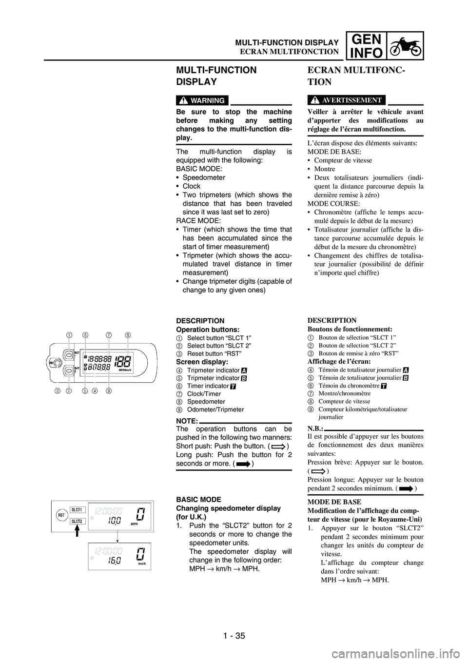
DESCRIPTION
Operation buttons:
1Select button “SLCT 1”
2Select button “SLCT 2”
3Reset button “RST”
Screen display:
4Tripmeter indicator
5Tripmeter indicator
6Timer indicator
7Clock/Timer
8Speedometer
9Odometer/Tripmeter
NOTE:The operation buttons can be
pushed in the following two manners:
Short push: Push the button. ( )
Long push: Push the button for 2
seconds or more. ( )
BASIC MODE
Changing speedometer display
(for U.K.)
1. Push the “SLCT2” button for 2
seconds or more to change the
speedometer units.
The speedometer display will
change in the following order:
MPH
→ km/h
→ MPH.
ECRAN MULTIFONC-
TION
AVERTISSEMENT
Veiller à arrêter le véhicule avant
d’apporter des modifications au
réglage de l’écran multifonction.
L’écran dispose des éléments suivants:
MODE DE BASE:
Compteur de vitesse
Montre
Deux totalisateurs journaliers (indi-
quent la distance parcourue depuis la
dernière remise à zéro)
MODE COURSE:
Chronomètre (affiche le temps accu-
mulé depuis le début de la mesure)
Totalisateur journalier (affiche la dis-
tance parcourue accumulée depuis le
début de la mesure du chronomètre)
Changement des chiffres de totalisa-
teur journalier (possibilité de définir
n’importe quel chiffre)
DESCRIPTION
Boutons de fonctionnement:
1
Bouton de sélection “SLCT 1”
2
Bouton de sélection “SLCT 2”
3
Bouton de remise à zéro “RST”
Affichage de l’écran:
4
Témoin de totalisateur journalier
5
Témoin de totalisateur journalier
6
Témoin du chronomètre
7
Montre/chronomètre
8
Compteur de vitesse
9
Compteur kilométrique/totalisateur
journalier
N.B.:
Il est possible d’appuyer sur les boutons
de fonctionnement des deux manières
suivantes:
Pression brève: Appuyer sur le bouton.
()
Pression longue: Appuyer sur le bouton
pendant 2 secondes minimum. ( )
MODE DE BASE
Modification de l’affichage du comp-
teur de vitesse (pour le Royaume-Uni)
1. Appuyer sur le bouton “SLCT2”
pendant 2 secondes minimum pour
changer les unités du compteur de
vitesse.
L’affichage du compteur change
dans l’ordre suivant:
MPH → km/h → MPH.
ECRAN MULTIFONCTION
Page 72 of 900
1 - 47
GEN
INFO
MULTI-FUNCTION DISPLAY
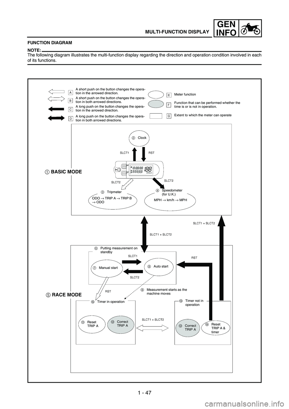
FUNCTION DIAGRAM
NOTE:The following diagram illustrates the multi-function display regarding the direction and operation condition involved in each
of its functions.
A short push on the button changes the opera-
tion in the arrowed direction.
A short push on the button changes the opera-
tion in both arrowed directions.
A long push on the button changes the opera-
tion in the arrowed direction.
A long push on the button changes the opera-
tion in both arrowed directions.Meter function
Function that can be performed whether the
time is or is not in operation.
Extent to which the meter can operate
2Clock
3Tripmeter4Speedometer
(for U.K.)
ODO
→ TRIP A
→ TRIP B
→ ODOMPH
→ km/h
→ MPH
6Putting measurement on
standby
7Manual start8Auto start
9Measurement starts as the
machine moves
0Timer in operation
AReset
TRIP ABCorrect
TRIP ACTimer not in
operation
BCorrect
TRIP ADReset
TRIP A &
timer
1BASIC MODE
5RACE MODE
Page 99 of 900
MAINTENANCE SPECIFICATIONS
2 - 6
SPEC
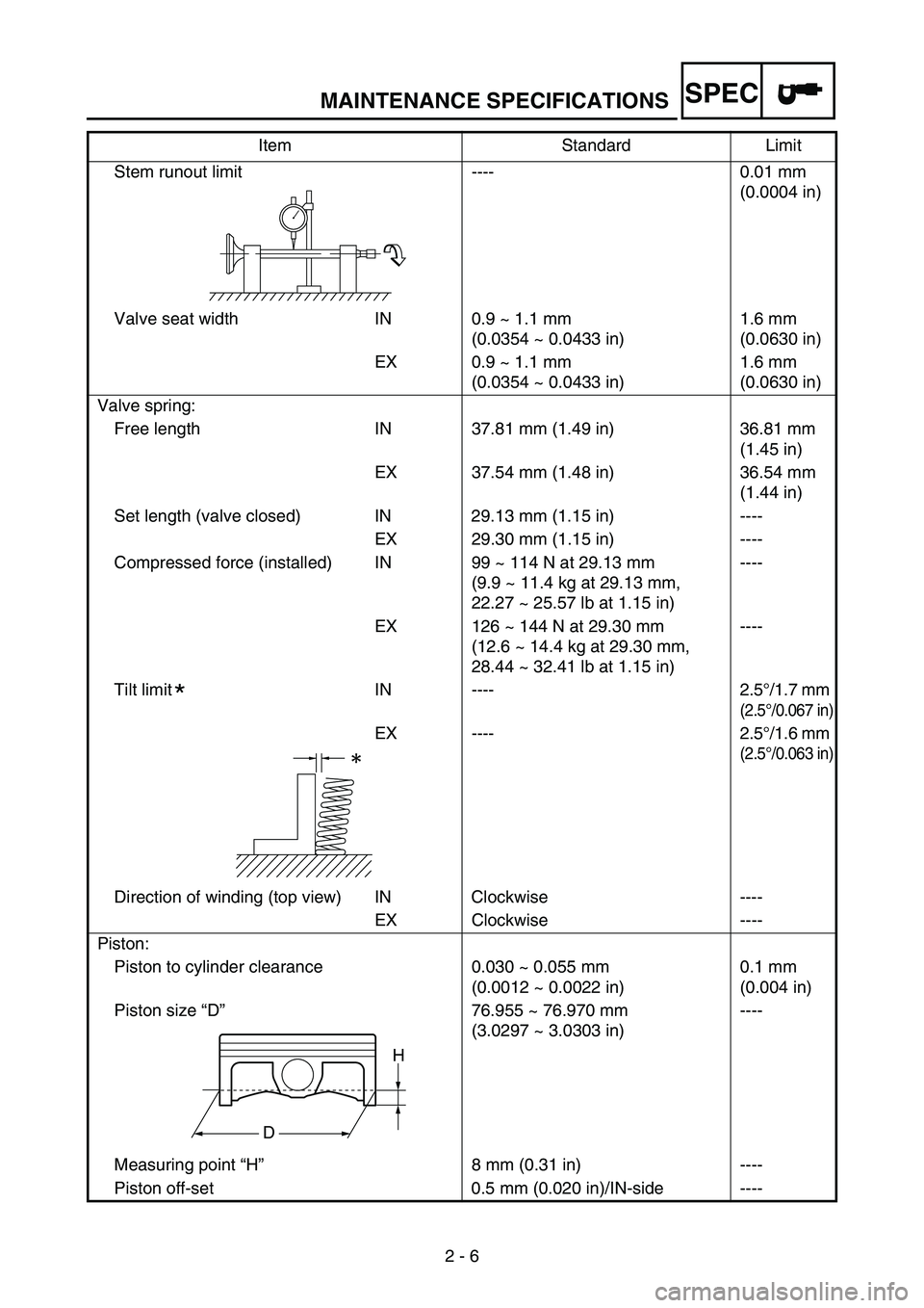
Stem runout limit ---- 0.01 mm
(0.0004 in)
Valve seat width IN 0.9 ~ 1.1 mm
(0.0354 ~ 0.0433 in)1.6 mm
(0.0630 in)
EX 0.9 ~ 1.1 mm
(0.0354 ~ 0.0433 in)1.6 mm
(0.0630 in)
Valve spring:
Free length IN 37.81 mm (1.49 in) 36.81 mm
(1.45 in)
EX 37.54 mm (1.48 in) 36.54 mm
(1.44 in)
Set length (valve closed) IN 29.13 mm (1.15 in) ----
EX 29.30 mm (1.15 in) ----
Compressed force (installed) IN 99 ~ 114 N at 29.13 mm
(9.9 ~ 11.4 kg at 29.13 mm,
22.27 ~ 25.57 lb at 1.15 in)----
EX 126 ~ 144 N at 29.30 mm
(12.6 ~ 14.4 kg at 29.30 mm,
28.44 ~ 32.41 lb at 1.15 in)----
Tilt limit IN ---- 2.5°/1.7 mm
(2.5°/0.067 in)
EX ---- 2.5°/1.6 mm
(2.5°/0.063 in)
Direction of winding (top view) IN Clockwise ----
EX Clockwise ----
Piston:
Piston to cylinder clearance 0.030 ~ 0.055 mm
(0.0012 ~ 0.0022 in)0.1 mm
(0.004 in)
Piston size “D”76.955 ~ 76.970 mm
(3.0297 ~ 3.0303 in)----
Measuring point “H”8 mm (0.31 in) ----
Piston off-set 0.5 mm (0.020 in)/IN-side ----Item Standard Limit
*
H
D
Page 228 of 900
3 - 21
INSP
ADJ
EC350000
ENGINE
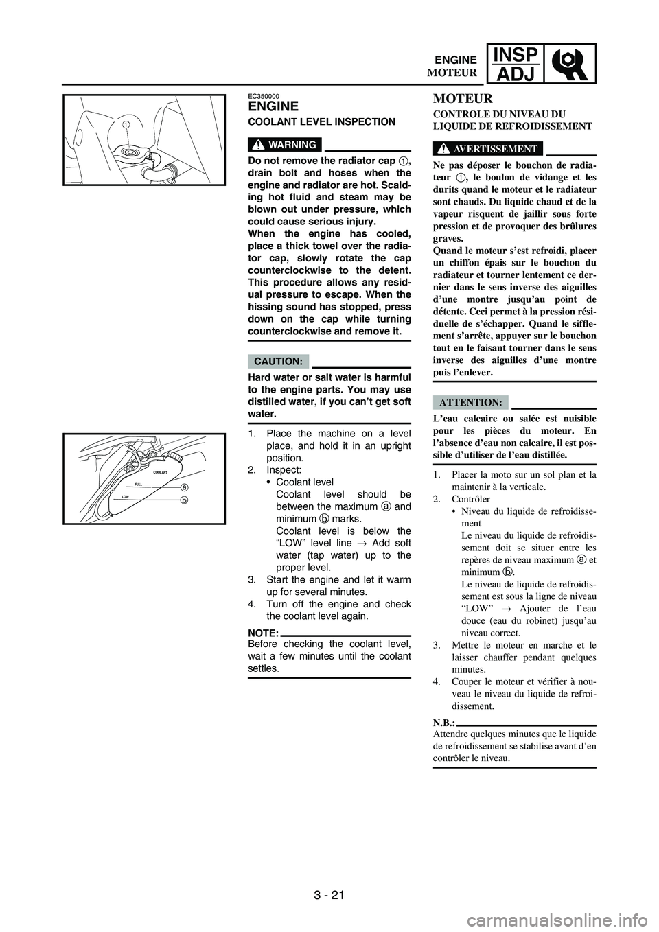
COOLANT LEVEL INSPECTION
WARNING
Do not remove the radiator cap 1,
drain bolt and hoses when the
engine and radiator are hot. Scald-
ing hot fluid and steam may be
blown out under pressure, which
could cause serious injury.
When the engine has cooled,
place a thick towel over the radia-
tor cap, slowly rotate the cap
counterclockwise to the detent.
This procedure allows any resid-
ual pressure to escape. When the
hissing sound has stopped, press
down on the cap while turning
counterclockwise and remove it.
CAUTION:
Hard water or salt water is harmful
to the engine parts. You may use
distilled water, if you can’t get soft
water.
1. Place the machine on a level
place, and hold it in an upright
position.
2. Inspect:
Coolant level
Coolant level should be
between the maximum
a and
minimum
b marks.
Coolant level is below the
“LOW” level line
→ Add soft
water (tap water) up to the
proper level.
3. Start the engine and let it warm
up for several minutes.
4. Turn off the engine and check
the coolant level again.
NOTE:Before checking the coolant level,
wait a few minutes until the coolant
settles.
LOWFULLCOOLANTa
b
MOTEUR
CONTROLE DU NIVEAU DU
LIQUIDE DE REFROIDISSEMENT
AVERTISSEMENT
Ne pas déposer le bouchon de radia-
teur 1
, le boulon de vidange et les
durits quand le moteur et le radiateur
sont chauds. Du liquide chaud et de la
vapeur risquent de jaillir sous forte
pression et de provoquer des brûlures
graves.
Quand le moteur s’est refroidi, placer
un chiffon épais sur le bouchon du
radiateur et tourner lentement ce der-
nier dans le sens inverse des aiguilles
d’une montre jusqu’au point de
détente. Ceci permet à la pression rési-
duelle de s’échapper. Quand le siffle-
ment s’arrête, appuyer sur le bouchon
tout en le faisant tourner dans le sens
inverse des aiguilles d’une montre
puis l’enlever.
ATTENTION:
L’eau calcaire ou salée est nuisible
pour les pièces du moteur. En
l’absence d’eau non calcaire, il est pos-
sible d’utiliser de l’eau distillée.
1. Placer la moto sur un sol plan et la
maintenir à la verticale.
2. Contrôler
Niveau du liquide de refroidisse-
ment
Le niveau du liquide de refroidis-
sement doit se situer entre les
repères de niveau maximum a et
minimum b.
Le niveau de liquide de refroidis-
sement est sous la ligne de niveau
“LOW” → Ajouter de l’eau
douce (eau du robinet) jusqu’au
niveau correct.
3. Mettre le moteur en marche et le
laisser chauffer pendant quelques
minutes.
4. Couper le moteur et vérifier à nou-
veau le niveau du liquide de refroi-
dissement.
N.B.:
Attendre quelques minutes que le liquide
de refroidissement se stabilise avant d’en
contrôler le niveau.
ENGINE
MOTEUR
Page 258 of 900

3 - 51
INSP
ADJ
5. Check:
Valve clearance
Out of specification
→ Adjust.
Valve clearance (cold):
Intake valve:
0.10 ~ 0.15 mm
(0.0039 ~ 0.0059 in)
Exhaust valve:
0.17 ~ 0.22 mm
(0.0067 ~ 0.0087 in)
Checking steps:
Turn the crankshaft counter-
clockwise with a wrench.
Align the T.D.C. mark
a on the
rotor with the align mark
b on
the crankcase cover when pis-
ton is at T.D.C. on compression
stroke.
NOTE:In order to be sure that the piston
is at Top Dead Center, the punch
mark
c on the exhaust camshaft
and the punch mark
d on the
intake camshaft must align with
the cylinder head surface, as
shown in the illustration.
Measure the valve clearance
e
using a feeler gauge
1.
NOTE:Record the measured reading if
the clearance is incorrect.
5. Contrôler:
Jeu aux soupapes
Hors spécifications → Ajuster.
Jeu aux soupapes (à froid):
Soupape d’admission:
0,10 à 0,15 mm
(0,0039 à 0,0059 in)
Soupape d’échappement:
0,17 à 0,22 mm
(0,0067 à 0,0087 in)
Etapes du contrôle:
Tourner le vilebrequin dans le sens
inverse des aiguilles d’une montre
à l’aide d’une clé.
Aligner le repère PMH a du rotor
avec le repère d’alignement b du
couvercle de carter lorsque le pis-
ton est au PMH de la course de
compression.
N.B.:
Le piston est au point mort haut lors-
que le repère poinçonné c de l’arbre
à cames d’échappement et le repère
poinçonné d de l’arbre à cames
d’admission sont alignés avec la sur-
face de la culasse comme le montre
l’illustration.
Mesurer le jeu aux soupapes e à
l’aide d’une jauge d’épaisseur à
lames 1.
N.B.:
Enregistrer la valeur mesurée si le jeu
est incorrect.
ENGINE
MOTEUR
Page 290 of 900
3 - 83
INSP
ADJ
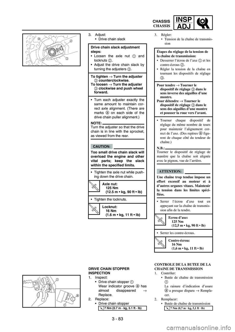
3. Adjust:
Drive chain slack
DRIVE CHAIN STOPPER
INSPECTION
1. Inspect:
Drive chain stopper
1
Wear indicator groove
a has
almost disappeared
→
Replace.
2. Replace:
Drive chain stopper Drive chain slack adjustment
steps:
Loosen the axle nut
1 and
locknuts
2.
Adjust the drive chain slack by
turning the adjusters
3.
To tighten → Turn the adjuster
3 counterclockwise.
To loosen → Turn the adjuster
3 clockwise and push wheel
forward.
Turn each adjuster exactly the
same amount to maintain cor-
rect axle alignment. (There are
marks
a on each side of the
drive chain puller alignment.)
NOTE:Turn the adjuster so that the drive
chain is in line with the sprocket,
as viewed from the rear.
CAUTION:
Too small drive chain slack will
overload the engine and other
vital parts; keep the slack
within the specified limits.
Tighten the axle nut while push-
ing down the drive chain.
T R..
Axle nut:
125 Nm
(12.5 m kg, 90 ft lb)
Tighten the locknuts.
T R..
Locknut:
16 Nm
(1.6 m kg, 11 ft lb)
T R..7 Nm (0.7 m · kg, 5.1 ft · lb)
1
1a
3. Régler:
Tension de la chaîne de transmis-
sion
CONTROLE DE LA BUTEE DE LA
CHAINE DE TRANSMISSION
1. Contrôler:
Butée de chaîne de transmission
1
La rainure d’indication d’usure
a a presque disparu → Rempla-
cer.
2. Remplacer:
Butée de chaîne de transmission Étapes du réglage de la tension de
la chaîne de transmission:
Desserrer l’écrou de l’axe 1 et les
contre-écrous 2.
Régler la tension de la chaîne en
tournant les dispositifs de réglage
3.
Pour tendre → Tourner le
dispositif de réglage 3 dans le
sens inverse des aiguilles d’une
montre.
Pour détendre → Tourner le
dispositif de réglage 3 dans le
sens des aiguilles d’une montre
et pousser la roue vers l’avant.
Tourner chaque dispositif de
réglage du même nombre de tours
pour maintenir l’alignement cor-
rect de l’axe. (Des repères a figu-
rent de chaque côté du tendeur de
chaîne.)
N.B.:
Tourner le dispositif de réglage de
manière que la chaîne soit alignée
avec le pignon, vue de l’arrière.
ATTENTION:
Une chaîne trop tendue impose un
effort excessif au moteur et à
d’autres organes vitaux. Maintenir
la tension dans les limites spéci-
fiées.
Serrer l’écrou d’axe tout en
appuyant sur la chaîne de transmis-
sion afin de la tendre.
T R..
Ecrou d’axe:
125 Nm
(12,5 m kg, 90 ft lb)
Serrer les contre-écrous.
T R..
Contre-écrou:
16 Nm
(1,6 m kg, 11 ft lb)
T R..7 Nm (0,7 m · kg, 5,1 ft · lb)
CHASSIS
CHASSIS
Page 358 of 900
4 - 17
ENGRADIATOR
EC456000HANDLING NOTE
WARNING
Do not remove the radiator cap
when the engine and radiator are
hot. Scalding hot fluid and steam
may be blown out under pressure,
which could cause serious injury.
When the engine has cooled, open
the radiator cap by the following
procedure:
Place a thick rag, like a towel, over
the radiator cap, slowly rotate the
cap counterclockwise to the
detent. This procedure allows any
residual pressure to escape. When
the hissing sound has stopped,
press down on the cap while turn-
ing counterclockwise and remove
it.
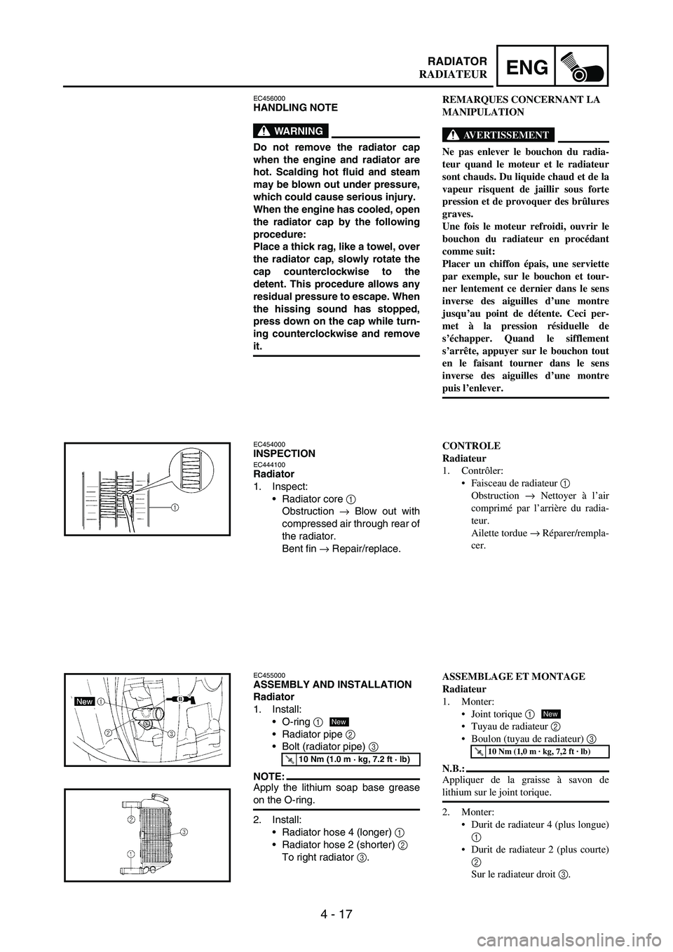
EC454000INSPECTIONEC444100Radiator
1. Inspect:
Radiator core
1
Obstruction
→ Blow out with
compressed air through rear of
the radiator.
Bent fin
→ Repair/replace.
EC455000ASSEMBLY AND INSTALLATION
Radiator
1. Install:
O-ring
1
Radiator pipe
2
Bolt (radiator pipe)
3
NOTE:Apply the lithium soap base grease
on the O-ring.
2. Install:
Radiator hose 4 (longer)
1
Radiator hose 2 (shorter)
2
To right radiator
3.
T R..10 Nm (1.0 m · kg, 7.2 ft · lb)
New
REMARQUES CONCERNANT LA
MANIPULATION
AVERTISSEMENT
Ne pas enlever le bouchon du radia-
teur quand le moteur et le radiateur
sont chauds. Du liquide chaud et de la
vapeur risquent de jaillir sous forte
pression et de provoquer des brûlures
graves.
Une fois le moteur refroidi, ouvrir le
bouchon du radiateur en procédant
comme suit:
Placer un chiffon épais, une serviette
par exemple, sur le bouchon et tour-
ner lentement ce dernier dans le sens
inverse des aiguilles d’une montre
jusqu’au point de détente. Ceci per-
met à la pression résiduelle de
s’échapper. Quand le sifflement
s’arrête, appuyer sur le bouchon tout
en le faisant tourner dans le sens
inverse des aiguilles d’une montre
puis l’enlever.
CONTROLE
Radiateur
1. Contrôler:
Faisceau de radiateur 1
Obstruction → Nettoyer à l’air
comprimé par l’arrière du radia-
teur.
Ailette tordue → Réparer/rempla-
cer.
ASSEMBLAGE ET MONTAGE
Radiateur
1. Monter:
Joint torique 1
Tuyau de radiateur 2
Boulon (tuyau de radiateur) 3
N.B.:
Appliquer de la graisse à savon de
lithium sur le joint torique.
2. Monter:
Durit de radiateur 4 (plus longue)
1
Durit de radiateur 2 (plus courte)
2
Sur le radiateur droit 3.
T R..10 Nm (1,0 m · kg, 7,2 ft · lb)
New
RADIATEUR
Page 406 of 900

4 - 65
ENGCAMSHAFTS
REMOVAL POINTS
Camshaft
1. Remove:
Timing mark accessing screw
1
Crankshaft end accessing
screw
2
2. Align:
T.D.C. mark
With align mark.
Checking steps:
Turn the crankshaft counter-
clockwise with a wrench.
Align the T.D.C. mark
a on the
rotor with the align mark
b on
the crankcase cover when pis-
ton is at T.D.C. on compression
stroke.
NOTE:In order to be sure that the piston
is at Top Dead Center, the punch
mark
c on the exhaust camshaft
and the punch mark
d on the
intake camshaft must align with
the cylinder head surface, as
shown in the illustration.
3. Remove:
Timing chain tensioner cap
bolt
1
Timing chain tensioner
2
Gasket
1
2
4. Remove:
Bolt (camshaft cap)
1
Camshaft cap
2
Clip
NOTE:Remove the bolts (camshaft cap) in a
crisscross pattern, working from the
outside in.
CAUTION:
The bolts (camshaft cap) must be
removed evenly to prevent dam-
age to the cylinder head, cam-
shafts or camshaft caps.
POINTS DE DEPOSE
Arbre à cames
1. Déposer:
Vis d’accès de repère d’allumage
1
Vis d’accès axiale du vilebrequin
2
2. Aligner:
Repère du PMH
Avec le repère d’alignement.
Etapes du contrôle:
Tourner le vilebrequin dans le sens
inverse des aiguilles d’une montre
à l’aide d’une clé.
Aligner le repère du PMH a du
rotor avec le repère d’alignement
b du couvercle de carter lorsque
le piston est au PMH de la course
de compression.
N.B.:
Le piston est au point mort haut lors-
que le repère poinçonné c de l’arbre
à cames d’échappement et le repère
poinçonné d de l’arbre à cames
d’admission sont alignés avec la sur-
face de la culasse comme le montre
l’illustration.
3. Déposer:
Boulon capuchon du tendeur de
chaîne de distribution 1
Tendeur de chaîne de distribu-
tion 2
Joint
4. Déposer:
Boulon
(chapeau d’arbre à cames) 1
Chapeau d’arbre à cames 2
Clip
N.B.:
Déposer les boulons (chapeau d’arbre à
cames) en croix, en procédant de l’exté-
rieur vers l’intérieur.
ATTENTION:
Les boulons (chapeau d’arbre à
cames) doivent être déposés uniformé-
ment pour prévenir tout endommage-
ment de la culasse, des arbres à cames
ou des chapeaux d’arbres à cames.
ARBRES A CAMES
Page 412 of 900

4 - 71
ENGCAMSHAFTS
Decompression system
1. Check:
Decompression system
Checking steps:
Check that the decompression
mechanism cam
1 moves
smoothly.
Check that the decompression
mechanism cam lever pin
2
projects from the camshaft.
Timing chain tensioner
1. Check:
While pressing the tensioner
rod lightly with fingers, use a
thin screwdriver
1 and wind
the tensioner rod up fully
clockwise.
When releasing the screw-
driver by pressing lightly with
fingers, make sure that the
tensioner rod will come out
smoothly.
If not, replace the tensioner
assembly.
ASSEMBLY AND INSTALLATION
Camshaft
1. Install:
Exhaust camshaft
1
Intake camshaft
2
Installation steps:
Turn the crankshaft counter-
clockwise with a wrench.
NOTE:Apply the molybdenum disulfide
oil on the camshafts.
Apply the engine oil on the
decompression system.
Squeezing the decompression
lever allows the crankshaft to
be turned easily.
Align the T.D.C. mark
a on the
rotor with the align mark
b on
the crankcase cover when pis-
ton is at T.D.C. on compression
stroke.
Décompresseur
1. Contrôler:
Décompresseur
Etapes du contrôle:
Contrôler que la came du décom-
presseur 1 se déplace correcte-
ment.
Contrôler que la goupille du levier
du décompresseur 2 dépasse de
l’arbre à cames.
Tendeur de chaîne de distribution
1. Contrôler:
Tout en appuyant légèrement sur
la tige du tendeur avec le doigt,
enrouler complètement la tige du
tendeur dans le sens des aiguilles
d’une montre à l’aide d’un fin
tournevis 1.
Contrôler, en appuyant légère-
ment avec le doigt, que la tige du
tendeur ressort librement lorsque
le tournevis est retiré.
Si ce n’est pas le cas, remplacer le
tendeur complet.
ASSEMBLAGE ET MONTAGE
Arbre à cames
1. Monter:
Arbre à cames d’échappement 1
Arbre à cames d’admission 2
Etapes du montage:
Tourner le vilebrequin dans le sens
inverse des aiguilles d’une montre
à l’aide d’une clé.
N.B.:
Appliquer de l’huile au bisulfure
de molybdène sur les arbres à
cames.
Appliquer de l’huile moteur sur le
décompresseur.
Appuyer sur le levier du décom-
presseur pour permettre au vilebre-
quin de tourner facilement.
Aligner le repère du PMH a du
rotor avec le repère d’alignement
b du couvercle de carter lorsque
le piston est au PMH de la course
de compression.
ARBRES A CAMES
Page 414 of 900

4 - 73
ENGCAMSHAFTS
Fit the timing chain
3 onto both
camshaft sprockets and install
the camshafts on the cylinder
head.
NOTE:The camshafts should be installed
onto the cylinder head so that the
punch mark
c on the exhaust
camshaft and the punch mark
d
on the intake camshaft must align
with the cylinder head surface, as
shown in the illustration.
CAUTION:
Do not turn the crankshaft dur-
ing the camshaft installation.
Damage or improper valve tim-
ing will result.
Install the clips, camshaft caps
4 and bolts (camshaft cap)
5.
T R..
Bolt (camshaft cap):
10 Nm
(1.0 m kg, 7.2 ft lb)
NOTE:Before removing the clips, cover
the cylinder head with a clean
rag to prevent the clips from into
the cylinder head cavity.
Apply the molybdenum disulfide
oil on the thread of the bolts
(camshaft cap).
Tighten the bolts (camshaft cap)
in a crisscross pattern.
CAUTION:
The bolts (camshaft cap) must
be tightened evenly, or damage
to the cylinder head, camshaft
caps, and camshaft will result.
5
4
M
2. Install:
Timing chain tensioner
Installation steps:
While pressing the tensioner
rod lightly with fingers, use a
thin screwdriver and wind the
tensioner rod up fully clockwise.
2. Monter:
Tendeur de chaîne de distribution Monter la chaîne de distribution 3
sur les deux pignons d’arbre à
cames et monter les arbres à cames
sur la culasse.
N.B.:
Les arbres à cames doivent être mon-
tées sur la culasse de manière que le
repère poinçonné c de l’arbre à
cames d’échappement et le repère
poinçonné d de l’arbre à cames
d’admission soient alignés avec la
surface de la culasse comme le mon-
tre l’illustration.
ATTENTION:
Ne pas faire tourner le vilebrequin
pendant l’installation de l’arbre à
cames. Cela provoquerait des dom-
mages ou un mauvais réglage du
calage de distribution.
Monter les clips, les chapeaux
d’arbres à cames 4 et les boulons
(chapeau d’arbre à cames) 5.
T R..
Boulon (chapeau d’arbre à
cames):
10 Nm
(1,0 m kg, 7,2 ft lb)
N.B.:
Avant de déposer les clips, couvrir
la culasse avec un chiffon propre
pour empêcher les clips de tomber
dans la cavité de la culasse.
Appliquer de l’huile au bisulfure de
molybdène sur les filets des boulons
(chapeau d’arbre à cames).
Serrer les boulons (chapeau d’arbre
à cames) en procédant en croix.
ATTENTION:
Les boulons (chapeau d’arbre à
cames) doivent être serrés uniformé-
ment sous peine d’endommager la
culasse, les chapeaux d’arbre à
cames et l’arbre à cames.
Etapes du montage:
Tout en appuyant légèrement sur la
tige du tendeur avec le doigt,
enrouler complètement la tige du
tendeur dans le sens des aiguilles
d’une montre à l’aide d’un fin tour-
nevis.
ARBRES A CAMES