air condition YAMAHA WR 250F 2017 Owners Manual
[x] Cancel search | Manufacturer: YAMAHA, Model Year: 2017, Model line: WR 250F, Model: YAMAHA WR 250F 2017Pages: 432, PDF Size: 14.14 MB
Page 44 of 432

STARTING AND BREAK-IN
1-30
EAS2GBB048
STARTING AND BREAK-IN
EAS2GBB049FUEL
Always use the recommended fuel as stated
below. Also, be sure to use new gasoline the
day of a race.
ECA
NOTICE
Use only unleaded gasoline. The use of
leaded gasoline will cause severe damage
to the engine internal parts such as valves,
piston rings, and exhaust system, etc.
TIP
Your Yamaha engine has been designed to use
premium unleaded gasoline with a pump oc-
tane number [(R+M)/2] of 91 or higher, or a re-
search octane number of 95 or higher. If
knocking (or pinging) occurs, use a gasoline of
a different brand.
EWA
WARNING
• For refueling, be sure to stop the engine
and use enough care not to spill any fuel.
Also be sure to avoid refueling close to a
fire.
• Refuel after the engine, exhaust pipe, etc.
have cooled off.
Gasohol (For USA and Canada)
There are two types of gasohol: gasohol con-
taining ethanol and that containing methanol.
Gasohol containing ethanol can be used if the
ethanol content does not exceed 10%. Gasohol
containing methanol is not recommended by
Yamaha because it can cause damage to the
fuel system or vehicle performance problems.
EAS2GBB050HANDLING NOTEEWA
WARNING
Never start or run the engine in a closed ar-
ea. The exhaust fumes are poisonous; they
can cause loss of consciousness and death
in a very short time. Always operate the ma-
chine in a well-ventilated area.
ECA
NOTICE
• Unlike a two-stroke engine, this engine
cannot be kick started when the throttle is
open because the kickstarter may kick
back. Also, if the throttle is open the air/
fuel mixture may be too lean for the engine
to start.
• Before starting the machine, perform the
checks in the pre-operation check list.
EAS2GBB051AIR FILTER MAINTENANCE
According to “CLEANING THE AIR FILTER
ELEMENT” section in the CHAPTER 3, apply
the Yamaha foam air filter oil or other quality
foam air filter oil to the element. (Excess oil in
the element may adversely affect engine start-
ing.)
EAS2GBB052STARTING A COLD ENGINEECA
NOTICE
For maximum engine life, never accelerate
hard when the engine is cold!
In order for the ignition circuit cut-off system to
enable starting, one of the following conditions
must be met:
• The transmission is in the neutral position.
• The transmission is in gear with the clutch le-
ver pulled.
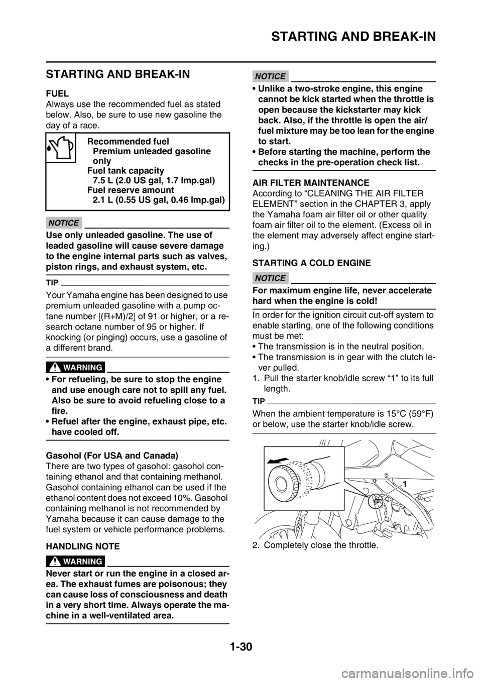
1. Pull the starter knob/idle screw “1” to its full
length.
TIP
When the ambient temperature is 15°C (59°F)
or below, use the starter knob/idle screw.
2. Completely close the throttle. Recommended fuel
Premium unleaded gasoline
only
Fuel tank capacity
7.5 L (2.0 US gal, 1.7 lmp.gal)
Fuel reserve amount
2.1 L (0.55 US gal, 0.46 lmp.gal)
1
Page 46 of 432

STARTING AND BREAK-IN
1-32
EAS2GBB053STARTING A WARM ENGINE
Follow the same procedure as for starting a
cold engine with the exception that the starter is
not required when the engine is warm.
TIP
If it fails to start, fully open the throttle grip and
give 10 to 20 slow kicks to clear the engine of
the rich air-fuel mixture retained in it.
EAS2GBB054BREAK-IN PROCEDURES
A break-in is important so that rotating portion,
sliding surfaces, and mounted areas may fit
one another, and that the rider may become ac-
customed to the machine.
ECA
NOTICE
Before running, do maintenance on the air
filter element.
Refer to “CLEANING THE AIR FILTER ELE-
MENT” on page 3-14.
1. After warming up the engine, drive it for
about 20 minutes at a throttle opening of 1/2
or less.
2. Make a pit stop, and check mounted areas
for looseness, oil leaks, or other problems.
3. Then, drive it for about 40 minutes at a throt-
tle opening of 3/4 or less.
4. Make a pit stop again, and thoroughly check
mounted areas for looseness, oil leaks, or
other problems. Thorough checks and ad-
justments are required in particular for
stretch of cables, free play of the brake,
stretch of the drive chain, looseness of the
spoke, and so on.
ECA
NOTICE
After a break-in or after each race, always
check the points shown in “TORQUE-
CHECK POINTS” for tightening torques and
retighten them. (Refer to “TORQUE-CHECK
POINTS” on page 1-34.)
Also when the following parts are replaced,
a break-in is required.
• Cylinder and Crankshaft: A break-in is re-
quired for about an hour.
• Piston, Piston ring, Valve, Camshaft, and
Gear: A break-in is required for about 30
minutes at a throttle opening of 1/2 or less.
Observe the condition of the engine careful-
ly during a break-in.
For checkpoints for a break-in, see “MAIN-
TENANCE AFTER BREAK-IN”. If any prob-
lem is found, immediately stop the engine
and make a checkup.
Page 59 of 432

ENGINE SPECIFICATIONS
2-6
Throttle body
Type/quantity 30RA-A95R/1
ID mark 2GB1 00
Fuel line pressure (at idle) 300.0–390.0 kPa (3.00–3.90 kgf/cm
2,
43.5–56.6 psi)
Throttle position sensor
Resistance 6.30 k
Output voltage (at idle) 0.48–0.52 V
Fuel injection sensor
Crankshaft position sensor resistance 228–342
Intake air pressure sensor output voltage 3.61–3.67 V at 101.3 kPa (3.61–3.67 V at
1.01 kgf/cm
2, 3.61–3.67 V at 14.7 psi)
Intake air temperature sensor resistance 5400.0–6600.0 at 0 °C (5400.0–6600.0
at 32 °F)
289–391 at 80 °C (289–391 at 176 °F)
Coolant temperature sensor resistance 2512–2777 at 20 °C (2512–2777 at 68 °F)
210–220 at 100 °C (210–220 at 212 °F)
Idling condition
Engine idling speed 1900–2100 r/min
CO% 3.0–4.0 % (USA) (CAN)
Intake vacuum 27.3 kPa (205 mmHg, 8.1 inHg) (USA) (CAN)
Water temperature 70–90 °C (158–194 °F)
Oil temperature 70–80 °C (158–176 °F)
Throttle grip free play 3.0–6.0 mm (0.12–0.24 in)
Page 101 of 432

PERIODIC MAINTENANCE
3-1
EAS2GBB074
PERIODIC MAINTENANCE
EAS2GBB075INTRODUCTION
This chapter includes all information necessary to perform recommended checks and adjustments.
If followed, these preventive maintenance procedures will ensure more reliable vehicle operation, a
longer service life and reduce the need for costly overhaul work. This information applies to vehicles
already in service as well as to new vehicles that are being prepared for sale. All service technicians
should be familiar with this entire chapter.
EAS2GBB076PERIODIC MAINTENANCE CHART FOR THE EMISSION CONTROL SYSTEM
TIP
• From 4200 mi (7000 km) or 9 months, repeat the maintenance intervals starting from 1800 mi (3000
km) or 3 months.
• Items marked with an asterisk should be performed by a Yamaha dealer as they require special
tools, data and technical skills.
NO. ITEM CHECKS AND MAINTENANCE JOBSINITIALODOMETER READ-
INGS
600 mi
(1000
km) or 1
month1800 mi
(3000
km) or 3
months3000 mi
(5000
km) or 6
months
1*Fuel line• Check fuel hoses for cracks or dam-
age.
• Replace if necessary.
2Spark plug• Check condition.
• Adjust gap and clean.
3*Valve clear-
ance• Check and adjust valve clearance
when engine is cold.
4*Air filter ele-
ment• Clean with solvent and apply Yamaha
foam air filter oil or other quality foam
air filter oil.
• Replace if necessary.
5*Breather
system• Check ventilation hose for cracks or
damage and drain any deposits.
• Replace. Every 2 years
6*Fuel injec-
tion• Adjust engine idling speed.
7Exhaust sys-
tem• Check for leakage.
• Tighten if necessary.
• Replace gasket(s) if necessary.
8Engine oil• Change (warm engine before drain-
ing).
9Engine oil fil-
ter element•Replace.
10Engine oil
strainer• Clean.
Page 145 of 432

CHASSIS
4-2
• Under a stony or a hard road condition, the
tire pressure should be higher to prevent a flat
tire.
EAS2GBB140FRONT FORK SETTING
The front fork setting should be made depend-
ing on the rider’s feeling of an actual run and
the circuit conditions.
The front fork setting includes the following
three factors:
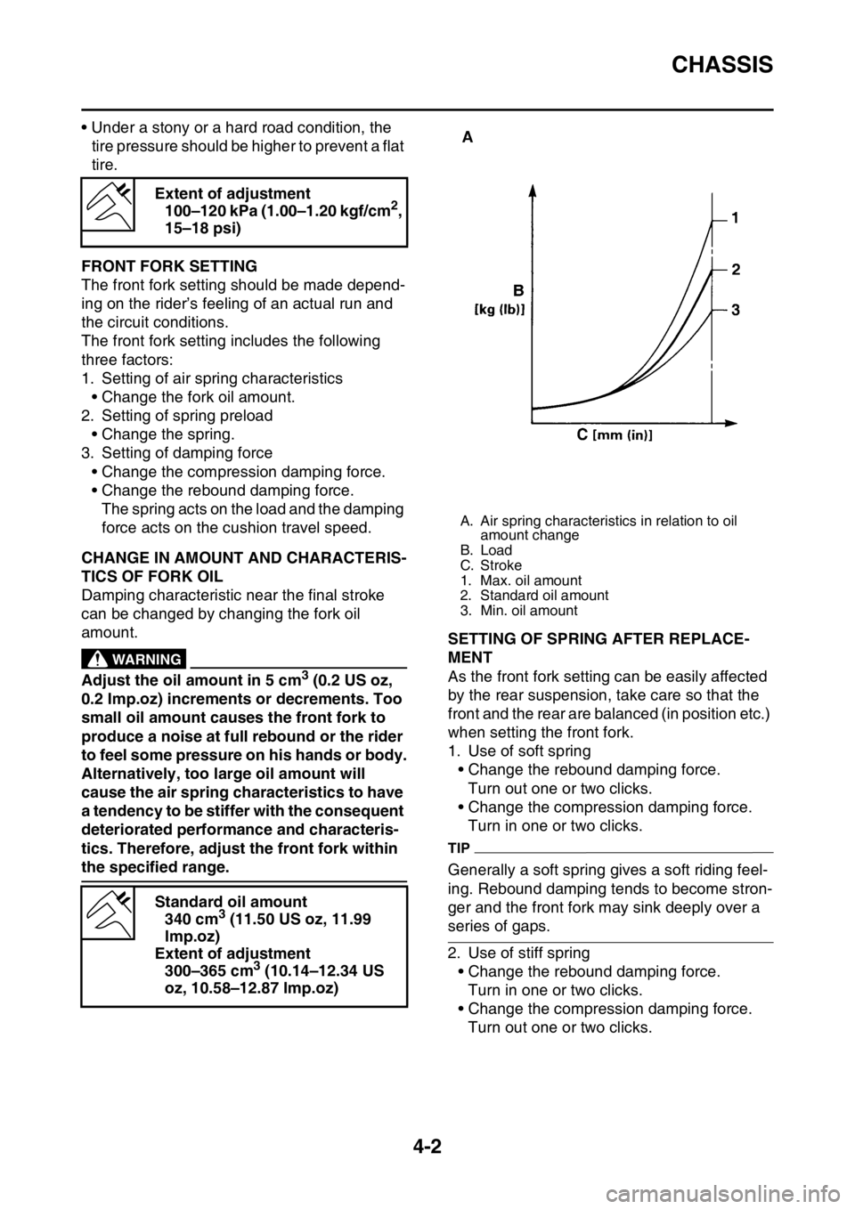
1. Setting of air spring characteristics
• Change the fork oil amount.
2. Setting of spring preload
• Change the spring.
3. Setting of damping force
• Change the compression damping force.
• Change the rebound damping force.
The spring acts on the load and the damping
force acts on the cushion travel speed.
EAS2GBB141CHANGE IN AMOUNT AND CHARACTERIS-
TICS OF FORK OIL
Damping characteristic near the final stroke
can be changed by changing the fork oil
amount.
EWA
WARNING
Adjust the oil amount in 5 cm3 (0.2 US oz,
0.2 Imp.oz) increments or decrements. Too
small oil amount causes the front fork to
produce a noise at full rebound or the rider
to feel some pressure on his hands or body.
Alternatively, too large oil amount will
cause the air spring characteristics to have
a tendency to be stiffer with the consequent
deteriorated performance and characteris-
tics. Therefore, adjust the front fork within
the specified range.
EAS2GBB142SETTING OF SPRING AFTER REPLACE-
MENT
As the front fork setting can be easily affected
by the rear suspension, take care so that the
front and the rear are balanced (in position etc.)
when setting the front fork.
1. Use of soft spring
• Change the rebound damping force.
Turn out one or two clicks.
• Change the compression damping force.
Turn in one or two clicks.
TIP
Generally a soft spring gives a soft riding feel-
ing. Rebound damping tends to become stron-
ger and the front fork may sink deeply over a
series of gaps.
2. Use of stiff spring
• Change the rebound damping force.
Turn in one or two clicks.
• Change the compression damping force.
Turn out one or two clicks. Extent of adjustment
100–120 kPa (1.00–1.20 kgf/cm
2,
15–18 psi)
Standard oil amount
340 cm
3 (11.50 US oz, 11.99
lmp.oz)
Extent of adjustment
300–365 cm
3 (10.14–12.34 US
oz, 10.58–12.87 Imp.oz)
A. Air spring characteristics in relation to oil
amount change
B. Load
C. Stroke
1. Max. oil amount
2. Standard oil amount
3. Min. oil amount
Page 354 of 432

LIGHTING SYSTEM
9-18
EAS2GBB366TROUBLESHOOTING
Any of the following fail to light: headlight or meter light.
TIP
Before troubleshooting, remove the following part (s):
1. Seat
2. Side cover (left)
3. Air scoop (left/right)
4. Fuel tank
1. Check the each bulbs condition.
Refer to “CHECKING THE BULBS
AND BULB SOCKETS” on page 9-
67.NG
Replace the bulb (s).
OK
2. Check the fuse.
Refer to “CHECKING THE FUSES”
on page 9-68.NG
Replace the fuse(s).
OK
3. Check the battery.
Refer to “CHECKING AND
CHARGING THE BATTERY” on
page 9-69.NG
• Clean the battery terminals.
• Recharge or replace the battery.
OK
4. Check the main relay.
Refer to “CHECKING THE RE-
LAYS” on page 9-72.NG
Replace the main relay.
OK
5. Check the headlight relay.
Refer to “CHECKING THE RE-
LAYS” on page 9-72.NG
Replace the headlight relay.
OK
6. Check the entire lighting system’s
wiring.
Refer to “CIRCUIT DIAGRAM” on
page 9-16.NG
Properly connect or repair the lighting sys-
tem’s wiring.
OK
Replace the ECU, meter assembly, or
taillight.
Page 367 of 432

FUEL INJECTION SYSTEM
9-31
ECU detects an abnormal signal from a sensor
If the ECU detects an abnormal signal from a sensor while the vehicle is being driven, the ECU illu-
minates the engine trouble warning light and provides the engine with alternate operating instructions
that are appropriate for the type of malfunction.
When an abnormal signal is received from a sensor, the ECU processes the specified values that are
programmed for each sensor in order to provide the engine with alternate operating instructions that
enable the engine to continue operating or stop operating, depending on the conditions.
EAS2GBB375TROUBLESHOOTING METHOD
The engine operation is not normal and the engine trouble warning light comes on.
1. Check:
• Fault code number
▼▼▼▼▼▼▼▼▼▼▼▼▼▼▼▼▼▼▼▼▼▼▼▼▼▼▼▼▼▼▼▼▼▼▼▼▼▼▼▼▼▼▼▼▼▼▼▼▼▼▼▼▼▼▼▼▼▼▼▼▼▼▼▼▼▼▼▼
a. Connect the Yamaha diagnostic tool. Refer to “YAMAHA DIAGNOSTIC TOOL” on page 9-32.
b. Check the fault code number displayed on the Yamaha diagnostic tool.
c. Identify the faulty system with the fault code number.
d. Identify the probable cause of the malfunction.
▲▲▲▲▲▲▲▲▲▲▲▲▲▲▲▲▲▲▲▲▲▲▲▲▲▲▲▲▲▲▲▲▲▲▲▲▲▲▲▲▲▲▲▲▲▲▲▲▲▲▲▲▲▲▲▲▲▲▲▲▲▲▲▲▲▲▲▲
2. Check and repair the probable cause of the malfunction.
3. Perform the reinstatement action for the fuel injection system. Refer to “Confirmation of service
completion” in the appropriate table in “TROUBLESHOOTING DETAILS” on page 9-35.
4. After pushing the engine stop switch, push the start switch to check whether the fault code number
is displayed.
TIP
If another fault code number is displayed, repeat steps (1) to (4) until no fault code number is dis-
played.
5. Erase the malfunction history in the diagnostic mode. Refer to “SENSOR OPERATION TABLE”
(Diagnostic code No.62).
TIP
Turning off the meter light will not erase the malfunction history.
The engine operation is not normal, but the engine trouble warning light does not come on.
1. Check the operation of the following sensors and actuators in the diagnostic mode. Refer to
“TROUBLESHOOTING DETAILS” on page 9-35.
If a malfunction is detected in the sensors or actuators, repair or replace all faulty parts.
If no malfunction is detected in the sensors and actuators, check and repair the inner parts of the
engine.Fault code No. No fault code No.
Check and repair. Refer to “TROUBLESHOOT-
ING DETAILS” on page 9-35.
Monitor the operation of the sensors and actua-
tors in the diagnostic mode. Refer to “TROU-
BLESHOOTING DETAILS” on page 9-35 and
“LIST OF SELF-DIAGNOSTIC AND FAIL-SAFE
ACTIONS” on page 10-5.Check and repair.
01: Throttle position sensor signal (throttle angle)
30: Ignition coil
36: Injector
Page 371 of 432

FUEL INJECTION SYSTEM
9-35
6. Condition
The current conditions are displayed. (Detected/Recovered)
7. Symptom
The symptoms of the detected malfunction are displayed.
8. Diagnosis code
The diagnosis codes related to the detected malfunction are displayed.
9. FFD (only for models that can display freeze frame data)
The mark “ ” is displayed when the freeze frame data is available.
10.ECU conduction time (hour: minute: second)
The total ECU conduction time (total hours the vehicle’s start switch was ON) when the malfunc-
tion was detected is displayed.
11.Number of main switch operation after detection
The number of times the meter light comes on by pushing the start switch between the malfunction
detection and code reading is displayed.
12.Number of occurrences
The number of malfunction occurrences between the malfunction detection and code reading is
displayed.
EAS2GBB377TROUBLESHOOTING DETAILS
This section describes the measures per fault code number displayed on the diagnostic tool. Check
and service the items or components that are the probable cause of the malfunction following the or-
der given.
After the check and service of the malfunctioning part have been completed, reset the diagnostic tool
display according to the reinstatement method.
Fault code No.:
Fault code number displayed on the diagnostic tool when the engine failed to work normally.
Diagnostic code No.:
Diagnostic code number to be used when the diagnostic mode is operated.
Fault code No. 12
ItemCrankshaft position sensor: no normal signals are received
from the crankshaft position sensor.
Fail-safe systemUnable to start engine
Unable to drive vehicle
Diagnostic code No.—
Diagnostic tool display—
Procedure—
ItemProbable cause of malfunc-
tion and checkMaintenance jobConfirmation of service
completion
1 Connection of crankshaft po-
sition sensor coupler.
Check the locking condition
of the coupler.
Disconnect the coupler and
check the pins (bent or bro-
ken terminals and locking
condition of the pins).Improperly connected
Connect the coupler securely
or repair/replace the wire har-
ness.Crank the engine.
Fault code number is not dis-
played Service is finished.
Fault code number is dis-
played Go to item 2.
Page 372 of 432

FUEL INJECTION SYSTEM
9-36
2 Connection of wire harness
ECU coupler.
Check the locking condition
of the coupler.
Disconnect the coupler and
check the pins (bent or bro-
ken terminals and locking
condition of the pins).Improperly connected
Connect the coupler securely
or repair/replace the wire har-
ness.Crank the engine.
Fault code number is not dis-
played Service is finished.
Fault code number is dis-
played Go to item 3.
3 Wire harness continuity. Open or short circuit Re-
place the wire harness.
Between the crankshaft posi-
tion sensor coupler and ECU
coupler.
black/blue–black/blue
gray–grayCrank the engine.
Fault code number is not dis-
played Service is finished.
Fault code number is dis-
played Go to item 4.
4 Installed condition of crank-
shaft position sensor.
Check for looseness or
pinching.
Check the gap between the
crankshaft position sensor
and the pickup rotor.Improperly installed sensor
Reinstall or replace the
sensor.
Refer to “GENERATOR AND
STARTER CLUTCH” on
page 6-66.Crank the engine.
Fault code number is not dis-
played Service is finished.
Fault code number is dis-
played Go to item 5.
5 Defective crankshaft position
sensor.Check the crankshaft position
sensor.
Refer to “CHECKING THE
CRANKSHAFT POSITION
SENSOR” on page 9-75.Crank the engine.
Fault code number is not dis-
played Service is finished.
Fault code number is dis-
played Go to item 6.
6 Malfunction in ECU. Replace the ECU. Fault code No. 12
ItemCrankshaft position sensor: no normal signals are received
from the crankshaft position sensor.
Page 373 of 432

FUEL INJECTION SYSTEM
9-37
TIP
• If fault code numbers 13 and 14 are both displayed, perform the checks and maintenance jobs for
fault code number 13 first.
• Before troubleshooting, disconnect the starter motor lead from the starter relay.
Fault code No. 13
Item Intake air pressure sensor: open or short circuit detected.
Fail-safe systemAble to start engine
Able to drive vehicle
Diagnostic code No.03
Diagnostic tool displayDisplays the intake air pressure.
ProcedureOperate the throttle while pushing the start switch.(If the display
value changes, the performance is OK.)
ItemProbable cause of malfunc-
tion and checkMaintenance jobConfirmation of service
completion
1 Connection of intake air pres-
sure sensor coupler.
Check the locking condition
of the coupler.
Disconnect the coupler and
check the pins (bent or bro-
ken terminals and locking
condition of the pins).Improperly connected
Connect the coupler securely
or repair/replace the wire har-
ness.Push the start switch.
Fault code number is not dis-
played Service is finished.
Fault code number is dis-
played Go to item 2.
2 Connection of wire harness
ECU coupler.
Check the locking condition
of the coupler.
Disconnect the coupler and
check the pins (bent or bro-
ken terminals and locking
condition of the pins).Improperly connected
Connect the coupler securely
or repair/replace the wire har-
ness.Push the start switch.
Fault code number is not dis-
played Service is finished.
Fault code number is dis-
played Go to item 3.
3 Wire harness continuity. Open or short circuit Re-
place the wire harness.
Between intake air pressure
sensor coupler and ECU cou-
pler.
black/blue–black/blue
pink–pink
blue–bluePush the start switch.
Fault code number is not dis-
played Service is finished.
Fault code number is dis-
played Go to item 4.
4 Installed condition of intake
air pressure sensor.
Check for looseness or
pinching.Improperly installed sensor
Reinstall or replace the
sensor.Push the start switch.
Fault code number is not dis-
played Service is finished.
Fault code number is dis-
played Go to item 5.