key YAMAHA WR 450F 2010 Owners Manual
[x] Cancel search | Manufacturer: YAMAHA, Model Year: 2010, Model line: WR 450F, Model: YAMAHA WR 450F 2010Pages: 230, PDF Size: 13.87 MB
Page 6 of 230

FOREWORD
INTRODUCTION
Congratulations on your purchase of
a Yamaha WR series. This model is
the culmination of Yamaha's vast ex-
perience in the production of paceset-
ting racing machines. It represents
the highest grade of craftsmanship
and reliability that have made Yama-
ha a leader.
This manual explains operation, in-
spection, basic maintenance and tun-
ing of your machine. If you have any
questions about this manual or your
machine, please contact your Yama-
ha dealer.
For Canada
The design and manufacture of this
Yamaha machine fully comply with
the emissions standards for clean air
applicable at the date of manufacture.
Yamaha has met these standards
without reducing the performance or
economy of operation of the machine.
To maintain these high standards, it
is important that you and your Yama-
ha dealer pay close attention to the
recommended maintenance sched-
ules and operating instructions con-
tained within this manual.
Yamaha continually seeks advance-
ments in product design and quality.
Therefore, while this manual contains
the most current product information
available at the time of printing, there
may be minor discrepancies between
your machine and this manual. If you
have any questions concerning this
manual, please consult your Yamaha
dealer.
PLEASE READ THIS MANUAL
CAREFULLY AND COMPLETELY
BEFORE OPERATING THIS MA-
CHINE. DO NOT ATTEMPT TO OP-
ERATE THIS MACHINE UNTIL YOU
HAVE ATTAINED A SATISFACTO-
RY KNOWLEDGE OF ITS CON-
TROLS AND OPERATING
FEATURES AND UNTIL YOU HAVE
BEEN TRAINED IN SAFE AND
PROPER RIDING TECHNIQUES.
REGULAR INSPECTIONS AND
CAREFUL MAINTENANCE,
ALONG WITH GOOD RIDING
SKILLS, WILL ENSURE THAT YOU
SAFETY ENJOY THE CAPABILI-
TIES AND THE RELIABILITY OF
THIS MACHINE.
IMPORTANT MANUAL
INFORMATION
Particularly important information is
distinguished in this manual by the
following notations.
This is the safety alert symbol. It is
used to alert you to potential per-
sonal injury hazards. Obey all safe-
ty messages that follow this
symbol to avoid possible injury or
death.
A WARNING indicat es a hazardous
situation which, if not avoided,
could result in death or serious in-
jury.
A NOTICE indicates special pre-
cautions that must be taken to
avoid damage to the vehicle or oth-
er property.
A TIP provides key information to
make procedures easier or clearer.
SAFETY INFORMATION
For Canada
This machine is designed for off-road
use only. It is illegal for this machine
to be operated on any public street,
road, or highway. Off-road use on
public lands may be illegal. Please
check local regulations before riding.
Except for Canada
THIS MACHINE IS DESIGNED
STRICTLY FOR COMPETITION
USE, ONLY ON A CLOSED
COURSE. It is illegal for this machine
to be operated on any public street,
road, or highway. Off-road use on
public lands may also be illegal.
Please check local regulations before
riding.
• THIS MACHINE IS TO BE OPER- ATED BY AN EXPERIENCED RID-
ER ONLY.
Do not attempt to operate this ma-
chine at maximum power until you
are totally familiar with its character-
istics.
• THIS MACHINE IS DESIGNED TO
BE RIDDEN BY THE OPERATOR
ONLY.
Do not carry passengers on this
machine. • ALWAYS WEAR PROTECTIVE
APPAREL.
When operating this machine, al-
ways wear an approved helmet with
goggles or a face shield. Also wear
heavy boots, gloves, and protective
clothing. Always wear proper fitting
clothing that will not be caught in
any of the moving parts or controls
of the machine.
• ALWAYS MAINTAIN YOUR MA- CHINE IN PROPER WORKING
ORDER.
For safety and reliability, the ma-
chine must be properly maintained.
Always perform the pre-operation
checks indicated in this manual.
Correcting a mechanical problem
before you ride may prevent an ac-
cident.
• GASOLINE IS HIGHLY FLAMMA- BLE.
Always turn off the engine while re-
fueling. Take care to not spill any
gasoline on the engine or exhaust
system. Never refuel in the vicinity
of an open flame, or while smoking.
• GASOLINE CAN CAUSE INJURY.
If you should swallow some gaso-
line, inhale excess gasoline vapors,
or allow any gasoline to get into
your eyes, contact a doctor immedi-
ately. If any gasoline spills onto
your skin or clothing, immediately
wash skin areas with soap and wa-
ter, and change your clothes.
• ONLY OPERATE THE MACHINE
IN AN AREA WITH ADEQUATE
VENTILATION.
Never start the engine or let it run
for any length of time in an enclosed
area. Exhaust fumes are poison-
ous. These fumes contain carbon
monoxide, which by itself is odor-
less and colorless. Carbon monox-
ide is a dangerous gas which can
cause unconsciousness or can be
lethal.
• PARK THE MACHINE CAREFUL- LY; TURN OFF THE ENGINE.
Always turn off the engine if you are
going to leave the machine. Do not
park the machine on a slope or soft
ground as it may fall over.
• THE ENGINE, EXHAUST PIPE, MUFFLER, AND OIL TANK WILL
BE VERY HOT AFTER THE EN-
GINE HAS BEEN RUN.
Be careful not to touch them or to
allow any clothing item to contact
them during inspection or repair.
Page 72 of 230

3-13
ENGINE
2. Adjust:
• Throttle grip free play
Throttle grip free play adjustment
steps:
a. Slide the adjuster cover.
b. Loosen the locknut "1".
c. Turn the adjuster "2" until the
specified free play is obtained.
d. Tighten the locknut.
Before adjusting the throttle cable
free play, the engine idle speed
should be adjusted.
After adjusting the throttle cable
free play, start the engine and turn
the handlebar to right and left and
make sure that the engine idling
does not run faster.
LUBRICATING THE THROTTLE
1. Remove:
• Cover (throttle cable cap) "1"
• Cover (grip cap) "2"
• Throttle grip cap "3"
2. Apply:
• Lithium soap base grease
On the throttle cable end "a".3. Install:
• Throttle grip cap
• Screw (throttle grip cap)
• Cover (grip cap)
• Cover (throttle cable cap)
ADJUSTING THE HOT STARTER
LEVER FREE PLAY
1. Check:
• Hot starter lever free play "a"
Out of specification→Adjust.
2. Adjust:
• Hot starter lever free play
Hot starter lever free play adjust-
ment steps:
a. Loosen the locknut "1".
b. Turn the adjuster "2" until free
play "a" is within the specified lim-
its.
c. Tighten the locknut.
After adjustment, check proper oper-
ation of hot starter.
CLEANING THE AIR FILTER
ELEMENT
Proper air filter maintenance is the
biggest key to preventing premature
engine wear and damage.
Never run the engine without the
air filter element in place; this
would allow dirt and dust to enter
the engine and cause rapid wear
and possible engine damage.
1. Open the air filter case cover "1"
Loosen the quick screw "2" and pull
on it to open the air filter case cover.
2. Unhook:
•Binder "1"
3. Remove:
• Air filter element "1"
• Air filter guide "2"
4. Clean:
• Air filter element
Clean them with solvent.
After cleaning, remove the remaining
solvent by squeezing the element.
• Do not twist the element when
squeezing the element.
• Leaving too much of solvent in
the element may result in poor
starting.
Locknut:
4 Nm (0.4 m•kg, 2.9
ft•lb)
Screw (throttle grip cap):
4 Nm (0.4 m•kg, 2.9
ft•lb)
Hot starter lever free play
"a":
3–6 mm (0.12–0.24 in)
Locknut:
4 Nm (0.4 m•kg, 2.9
ft•lb)
Page 141 of 230

5-38
BALANCER
BALANCER
REMOVING THE BALANCER
Order Part name Q'ty Remarks
Primary driven gear Refer to "CLUTCH" section.
Right crankcase cover Refer to "OIL FILTER ELEMENT AND WA-
TER PUMP" section.
Stator Refer to "CDI MAGNETO" section.
1 Nut (balancer) 1 Refer to removal section.
2 Nut (primary drive gear) 1 Refer to removal section.
3 Nut (balancer shaft driven gear) 1 Refer to removal section.
4 Lock washer 1
5 Balancer 1
6 Straight key 1
7 Conical washer 1
8 Primary drive gear 1
9 Balancer shaft drive gear 1
10 Lock washer 1
11 Balancer shaft driven gear 1
Page 142 of 230

5-39
BALANCER
REMOVING THE BALANCER
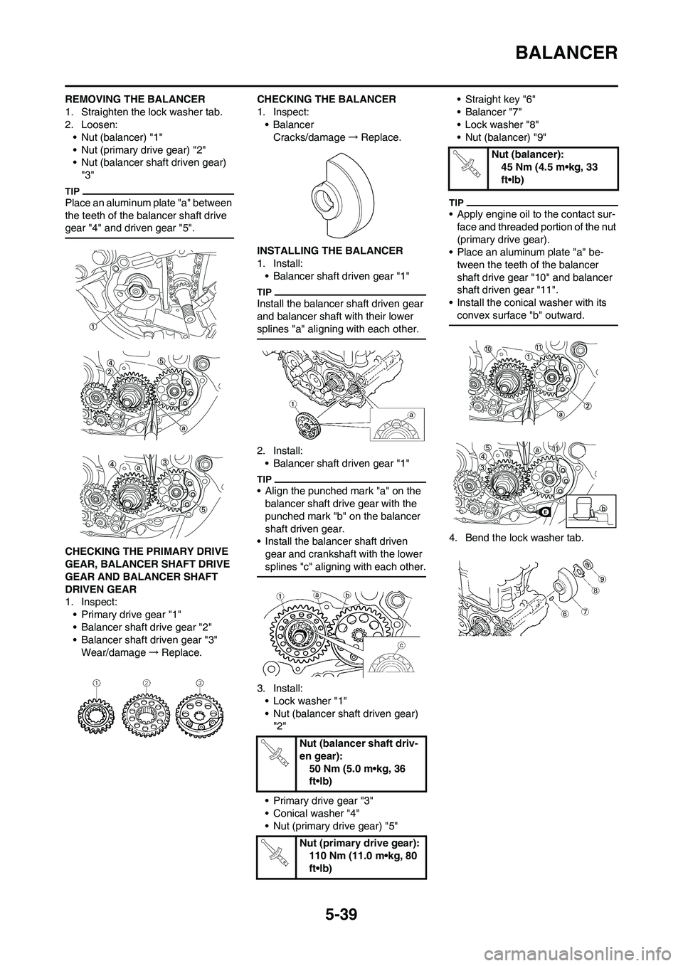
1. Straighten the lock washer tab.
2. Loosen:
• Nut (balancer) "1"
• Nut (primary drive gear) "2"
• Nut (balancer shaft driven gear)
"3"
Place an aluminum plate "a" between
the teeth of the balancer shaft drive
gear "4" and driven gear "5".
CHECKING THE PRIMARY DRIVE
GEAR, BALANCER SHAFT DRIVE
GEAR AND BALANCER SHAFT
DRIVEN GEAR
1. Inspect:
• Primary drive gear "1"
• Balancer shaft drive gear "2"
• Balancer shaft driven gear "3"
Wear/damage→Replace.CHECKING THE BALANCER
1. Inspect:
• Balancer
Cracks/damage→Replace.
INSTALLING THE BALANCER
1. Install:
• Balancer shaft driven gear "1"
Install the balancer shaft driven gear
and balancer shaft with their lower
splines "a" aligning with each other.
2. Install:
• Balancer shaft driven gear "1"
• Align the punched mark "a" on the
balancer shaft drive gear with the
punched mark "b" on the balancer
shaft driven gear.
• Install the balancer shaft driven
gear and crankshaft with the lower
splines "c" aligning with each other.
3. Install:
• Lock washer "1"
• Nut (balancer shaft driven gear)
"2"
• Primary drive gear "3"
• Conical washer "4"
• Nut (primary drive gear) "5"• Straight key "6"
• Balancer "7"
• Lock washer "8"
• Nut (balancer) "9"
• Apply engine oil to the contact sur-
face and threaded portion of the nut
(primary drive gear).
• Place an aluminum plate "a" be-
tween the teeth of the balancer
shaft drive gear "10" and balancer
shaft driven gear "11".
• Install the conical washer with its
convex surface "b" outward.
4. Bend the lock washer tab.
Nut (balancer shaft driv-
en gear):
50 Nm (5.0 m•kg, 36
ft•lb)
Nut (primary drive gear):
110 Nm (11.0 m•kg, 80
ft•lb)
Nut (balancer):
45 Nm (4.5 m•kg, 33
ft•lb)
Page 152 of 230

5-49
AC MAGNETO AND STARTER CLUTCH
Tighten the rotor nut to 65 Nm (6.5 m•kg, 47 ft•lb), loosen and retighten the rotor nut to 65 Nm (6.5 m•kg, 47 ft•lb).
12 Woodruff key 1
13 Starter clutch assembly cover 1 Refer to removal section.
14 Starter clutch 1 Refer to removal section.
15 Starter clutch drive gear 1
16 Holder 1
17 Pickup coil 1
18 Stator 1 Order Part name Q'ty Remarks
Page 153 of 230

5-50
AC MAGNETO AND STARTER CLUTCH
REMOVING THE ROTOR
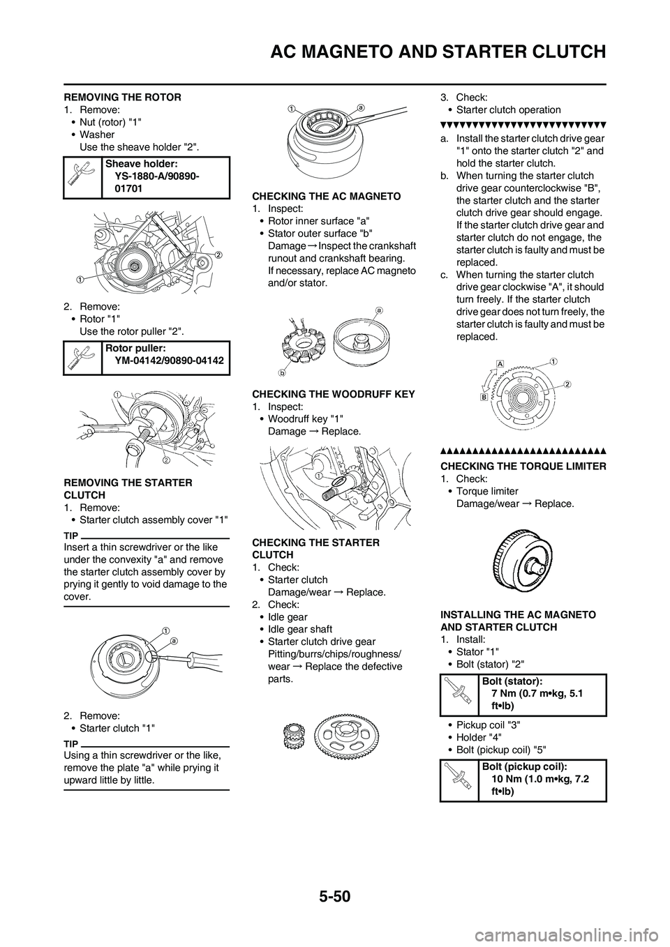
1. Remove:
• Nut (rotor) "1"
• Washer
Use the sheave holder "2".
2. Remove:
• Rotor "1"
Use the rotor puller "2".
REMOVING THE STARTER
CLUTCH
1. Remove:
• Starter clutch assembly cover "1"
Insert a thin screwdriver or the like
under the convexity "a" and remove
the starter clutch assembly cover by
prying it gently to void damage to the
cover.
2. Remove:
• Starter clutch "1"
Using a thin screwdriver or the like,
remove the plate "a" while prying it
upward little by little.
CHECKING THE AC MAGNETO
1. Inspect:
• Rotor inner surface "a"
• Stator outer surface "b"
Damage→Inspect the crankshaft
runout and crankshaft bearing.
If necessary, replace AC magneto
and/or stator.
CHECKING THE WOODRUFF KEY
1. Inspect:
• Woodruff key "1"
Damage→Replace.
CHECKING THE STARTER
CLUTCH
1. Check:
• Starter clutch
Damage/wear→Replace.
2. Check:
• Idle gear
• Idle gear shaft
• Starter clutch drive gear
Pitting/burrs/chips/roughness/
wear→Replace the defective
parts.3. Check:
• Starter clutch operation
a. Install the starter clutch drive gear
"1" onto the starter clutch "2" and
hold the starter clutch.
b. When turning the starter clutch
drive gear counterclockwise "B",
the starter clutch and the starter
clutch drive gear should engage.
If the starter clutch drive gear and
starter clutch do not engage, the
starter clutch is faulty and must be
replaced.
c. When turning the starter clutch
drive gear clockwise "A", it should
turn freely. If the starter clutch
drive gear does not turn freely, the
starter clutch is faulty and must be
replaced.
CHECKING THE TORQUE LIMITER
1. Check:
• Torque limiter
Damage/wear→Replace.
INSTALLING THE AC MAGNETO
AND STARTER CLUTCH
1. Install:
• Stator "1"
• Bolt (stator) "2"
• Pickup coil "3"
• Holder "4"
• Bolt (pickup coil) "5" Sheave holder:
YS-1880-A/90890-
01701
Rotor puller:
YM-04142/90890-04142
Bolt (stator):
7 Nm (0.7 m•kg, 5.1
ft•lb)
Bolt (pickup coil):
10 Nm (1.0 m•kg, 7.2
ft•lb)
Page 154 of 230

5-51
AC MAGNETO AND STARTER CLUTCH
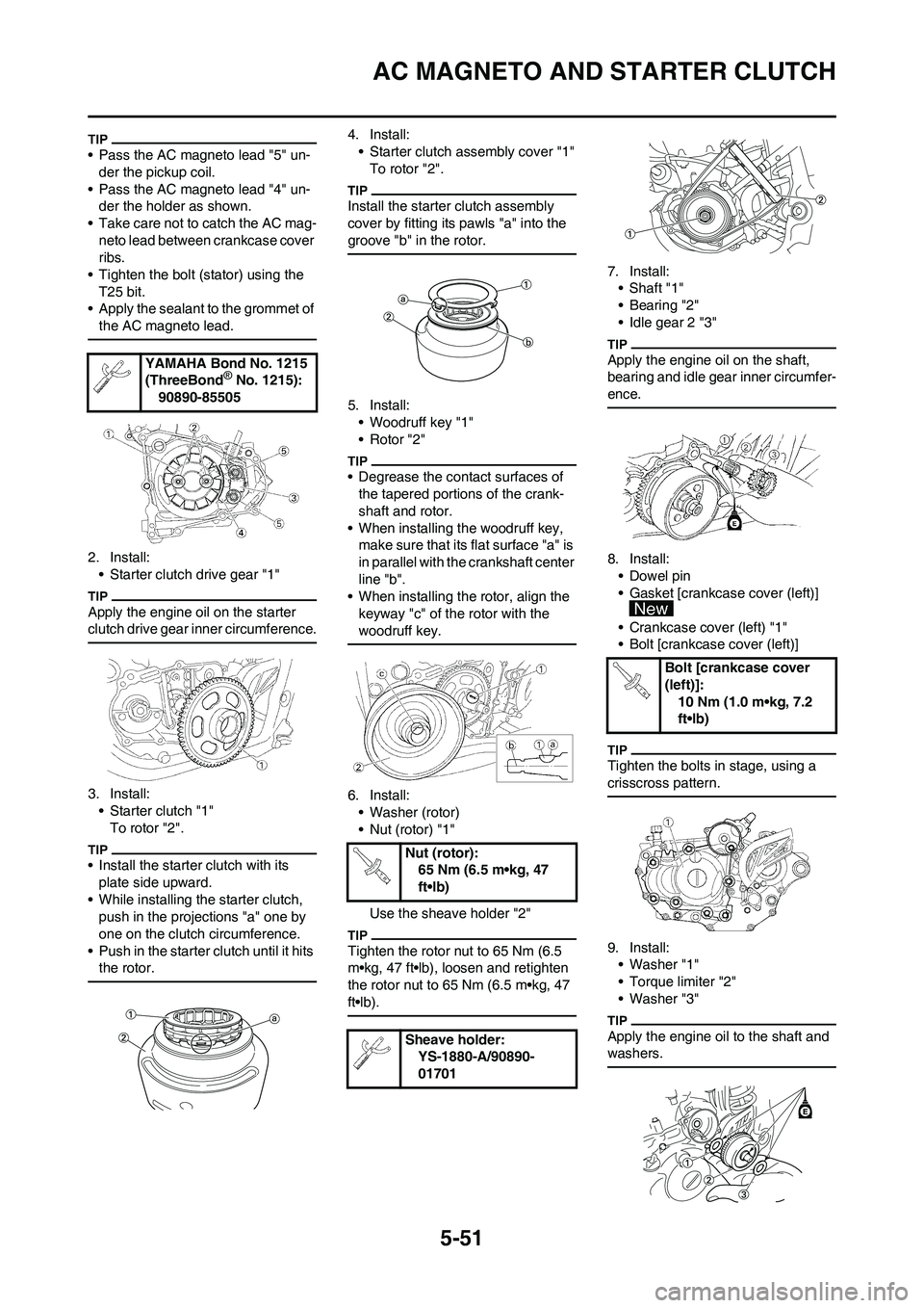
• Pass the AC magneto lead "5" un-
der the pickup coil.
• Pass the AC magneto lead "4" un-
der the holder as shown.
• Take care not to catch the AC mag-
neto lead between crankcase cover
ribs.
• Tighten the bolt (stator) using the
T25 bit.
• Apply the sealant to the grommet of
the AC magneto lead.
2. Install:
• Starter clutch drive gear "1"
Apply the engine oil on the starter
clutch drive gear inner circumference.
3. Install:
• Starter clutch "1"
To rotor "2".
• Install the starter clutch with its
plate side upward.
• While installing the starter clutch,
push in the projections "a" one by
one on the clutch circumference.
• Push in the starter clutch until it hits
the rotor.
4. Install:
• Starter clutch assembly cover "1"
To rotor "2".
Install the starter clutch assembly
cover by fitting its pawls "a" into the
groove "b" in the rotor.
5. Install:
• Woodruff key "1"
• Rotor "2"
• Degrease the contact surfaces of
the tapered portions of the crank-
shaft and rotor.
• When installing the woodruff key,
make sure that its flat surface "a" is
in parallel with the crankshaft center
line "b".
• When installing the rotor, align the
keyway "c" of the rotor with the
woodruff key.
6. Install:
• Washer (rotor)
• Nut (rotor) "1"
Use the sheave holder "2"
Tighten the rotor nut to 65 Nm (6.5
m•kg, 47 ft•lb), loosen and retighten
the rotor nut to 65 Nm (6.5 m•kg, 47
ft•lb).
7. Install:
• Shaft "1"
• Bearing "2"
• Idle gear 2 "3"
Apply the engine oil on the shaft,
bearing and idle gear inner circumfer-
ence.
8. Install:
• Dowel pin
• Gasket [crankcase cover (left)]
• Crankcase cover (left) "1"
• Bolt [crankcase cover (left)]
Tighten the bolts in stage, using a
crisscross pattern.
9. Install:
• Washer "1"
• Torque limiter "2"
• Washer "3"
Apply the engine oil to the shaft and
washers.
YAMAHA Bond No. 1215
(ThreeBond® No. 1215):
90890-85505
Nut (rotor):
65 Nm (6.5 m•kg, 47
ft•lb)
Sheave holder:
YS-1880-A/90890-
01701
Bolt [crankcase cover
(left)]:
10 Nm (1.0 m•kg, 7.2
ft•lb)