check engine YAMAHA XMAX 125 2013 Owner's Manual
[x] Cancel search | Manufacturer: YAMAHA, Model Year: 2013, Model line: XMAX 125, Model: YAMAHA XMAX 125 2013Pages: 96, PDF Size: 4.83 MB
Page 61 of 96
PERIODIC MAINTENANCE AND ADJUSTMENT
6-13
6
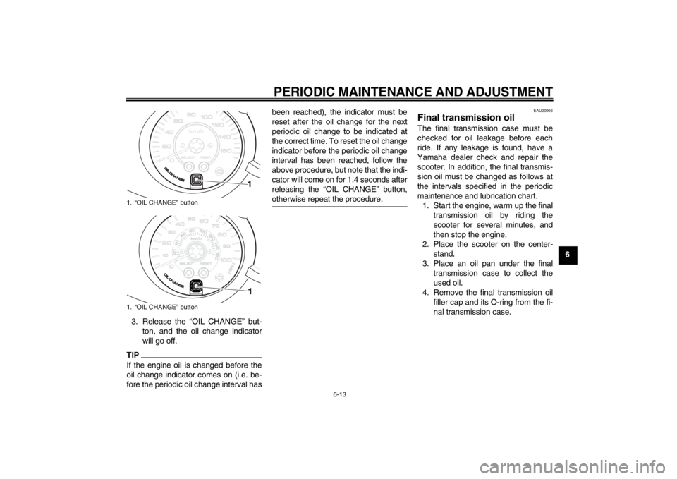
3. Release the “OIL CHANGE” but-
ton, and the oil change indicator
will go off.
TIPIf the engine oil is changed before the
oil change indicator comes on (i.e. be-
fore the periodic oil change interval hasbeen reached), the indicator must be
reset after the oil change for the next
periodic oil change to be indicated at
the correct time. To reset the oil change
indicator before the periodic oil change
interval has been reached, follow the
above procedure, but note that the indi-
cator will come on for 1.4 seconds after
releasing the “OIL CHANGE” button,
otherwise repeat the procedure.
EAU20066
Final transmission oil The final transmission case must be
checked for oil leakage before each
ride. If any leakage is found, have a
Yamaha dealer check and repair the
scooter. In addition, the final transmis-
sion oil must be changed as follows at
the intervals specified in the periodic
maintenance and lubrication chart.
1. Start the engine, warm up the final
transmission oil by riding the
scooter for several minutes, and
then stop the engine.
2. Place the scooter on the center-
stand.
3. Place an oil pan under the final
transmission case to collect the
used oil.
4. Remove the final transmission oil
filler cap and its O-ring from the fi-
nal transmission case.
1. “OIL CHANGE” button
1. “OIL CHANGE” button
U2ABE2E0.book Page 13 Thursday, August 30, 2012 2:36 PM
Page 62 of 96
PERIODIC MAINTENANCE AND ADJUSTMENT
6-14
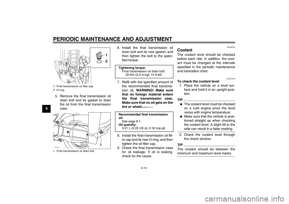
65. Remove the final transmission oil
drain bolt and its gasket to drain
the oil from the final transmission
case.6. Install the final transmission oil
drain bolt and its new gasket, and
then tighten the bolt to the speci-
fied torque.
7. Refill with the specified amount of
the recommended final transmis-
sion oil. WARNING! Make sure
that no foreign material enters
the final transmission case.
Make sure that no oil gets on the
tire or wheel.
[EWA11311]
8. Install the final transmission oil fill-
er cap and its new O-ring, and then
tighten the oil filler cap.
9. Check the final transmission case
for oil leakage. If oil is leaking,
check for the cause.
EAU20070
Coolant The coolant level should be checked
before each ride. In addition, the cool-
ant must be changed at the intervals
specified in the periodic maintenance
and lubrication chart.
EAUS1670
To check the coolant level
1. Place the vehicle on a level sur-
face and hold it in an upright posi-
tion.TIP●
The coolant level must be checked
on a cold engine since the level
varies with engine temperature.
●
Make sure that the vehicle is posi-
tioned straight up when checking
the coolant level. A slight tilt to the
side can result in a false reading.
2. Check the coolant level through
the check window.TIPThe coolant should be between the
minimum and maximum level marks.
1. Final transmission oil filler cap
2. O-ring
1. Final transmission oil drain boltZAUM0703
1
Tightening torque:
Final transmission oil drain bolt:
20 Nm (2.0 m·kgf, 14 ft·lbf)
Recommended final transmission
oil:
See page 8-1.
Oil quantity:
0.21 L (0.22 US qt, 0.18 Imp.qt)
U2ABE2E0.book Page 14 Thursday, August 30, 2012 2:36 PM
Page 63 of 96
PERIODIC MAINTENANCE AND ADJUSTMENT
6-15
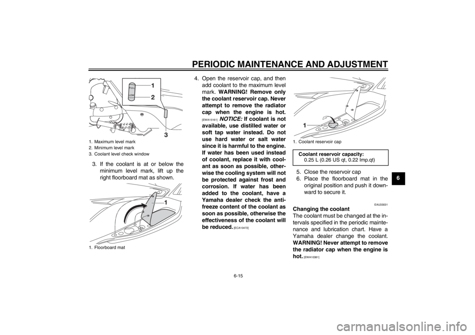
6 3. If the coolant is at or below the
minimum level mark, lift up the
right floorboard mat as shown.4. Open the reservoir cap, and then
add coolant to the maximum level
mark. WARNING! Remove only
the coolant reservoir cap. Never
attempt to remove the radiator
cap when the engine is hot.
[EWA15161]
NOTICE: If coolant is not
available, use distilled water or
soft tap water instead. Do not
use hard water or salt water
since it is harmful to the engine.
If water has been used instead
of coolant, replace it with cool-
ant as soon as possible, other-
wise the cooling system will not
be protected against frost and
corrosion. If water has been
added to the coolant, have a
Yamaha dealer check the anti-
freeze content of the coolant as
soon as possible, otherwise the
effectiveness of the coolant will
be reduced.
[ECA10472]
5. Close the reservoir cap
6. Place the floorboard mat in the
original position and push it down-
ward to secure it.
EAU33031
Changing the coolant
The coolant must be changed at the in-
tervals specified in the periodic mainte-
nance and lubrication chart. Have a
Yamaha dealer change the coolant.
WARNING! Never attempt to remove
the radiator cap when the engine is
hot.
[EWA10381]
1. Maximum level mark
2. Minimum level mark
3. Coolant level check window
1. Floorboard mat
1. Coolant reservoir cap
Coolant reservoir capacity:
0.25 L (0.26 US qt, 0.22 Imp.qt)
U2ABE2E0.book Page 15 Thursday, August 30, 2012 2:36 PM
Page 65 of 96
PERIODIC MAINTENANCE AND ADJUSTMENT
6-17
6 4. Install the air filter element with the
colored side facing outward.
5. Install the V-belt case air filter cov-
ers by installing the screws.
NOTICE: Make sure that each fil-
ter element is properly seated in
its case. The engine should nev-
er be operated without the filter
elements installed, otherwise
the piston(s) and/or cylinder(s)
may become excessively worn.
[ECA10531]EAU48432
Adjusting the throttle grip free
play The throttle grip free play should mea-
sure 3.0–5.0 mm (0.12–0.20 in) at the
inner edge of the throttle grip. Periodi-
cally check the throttle grip free play
and, if necessary, adjust it as follows.TIPThe engine idling speed must be cor-
rectly adjusted before checking and ad-
justing the throttle grip free play.1. Slide the rubber cover back.
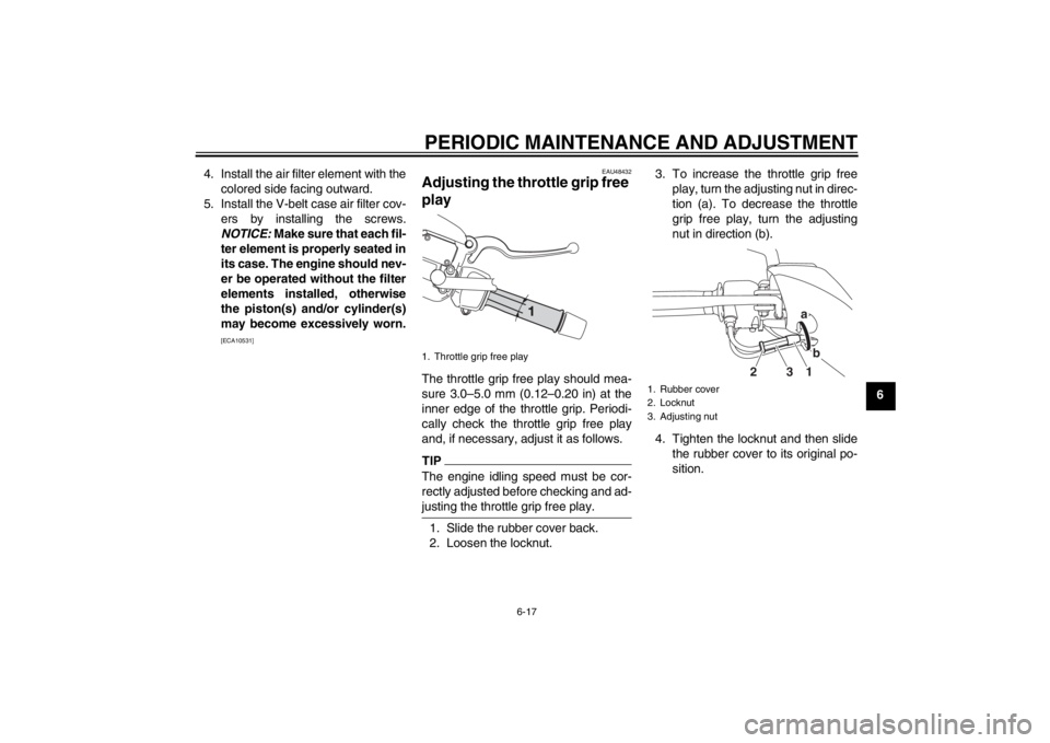
2. Loosen the locknut.3. To increase the throttle grip free
play, turn the adjusting nut in direc-
tion (a). To decrease the throttle
grip free play, turn the adjusting
nut in direction (b).
4. Tighten the locknut and then slide
the rubber cover to its original po-
sition.1. Throttle grip free play
1. Rubber cover
2. Locknut
3. Adjusting nut
1b a
3 2
U2ABE2E0.book Page 17 Thursday, August 30, 2012 2:36 PM
Page 66 of 96
PERIODIC MAINTENANCE AND ADJUSTMENT
6-18
6
EAU21401
Valve clearance The valve clearance changes with use,
resulting in improper air-fuel mixture
and/or engine noise. To prevent this
from occurring, the valve clearance
must be adjusted by a Yamaha dealer
at the intervals specified in the periodic
maintenance and lubrication chart.
EAU21876
Tires Tires are the only contact between the
vehicle and the road. Safety in all con-
ditions of riding depends on a relatively
small area of road contact. Therefore, it
is essential to maintain the tires in good
condition at all times and replace them
at the appropriate time with the speci-
fied tires.
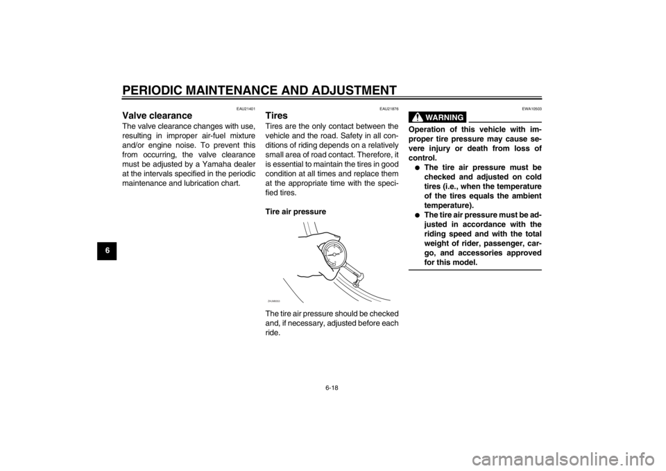
Tire air pressure
The tire air pressure should be checked
and, if necessary, adjusted before each
ride.
WARNING
EWA10503
Operation of this vehicle with im-
proper tire pressure may cause se-
vere injury or death from loss of
control.●
The tire air pressure must be
checked and adjusted on cold
tires (i.e., when the temperature
of the tires equals the ambient
temperature).
●
The tire air pressure must be ad-
justed in accordance with the
riding speed and with the total
weight of rider, passenger, car-
go, and accessories approved
for this model.
ZAUM0053
U2ABE2E0.book Page 18 Thursday, August 30, 2012 2:36 PM
Page 72 of 96

PERIODIC MAINTENANCE AND ADJUSTMENT
6-24
6
EAU22732
Changing the brake fluid Have a Yamaha dealer change the
brake fluid at the intervals specified in
the periodic maintenance and lubrica-
tion chart. In addition, have the oil seals
of the master cylinders and calipers as
well as the brake hoses replaced at the
intervals listed below or whenever they
are damaged or leaking.●
Oil seals: Replace every two
years.
●
Brake hoses: Replace every four
years.
EAU23095
Checking and lubricating the
cables The operation of all control cables and
the condition of the cables should be
checked before each ride, and the ca-
bles and cable ends should be lubricat-
ed if necessary. If a cable is damaged
or does not move smoothly, have a
Yamaha dealer check or replace it.
WARNING! Damage to the outer
housing of cables may result in in-
ternal rusting and cause interfer-
ence with cable movement. Replace
damaged cables as soon as possi-
ble to prevent unsafe conditions.[EWA10711]EAU23114
Checking and lubricating the
throttle grip and cable The operation of the throttle grip should
be checked before each ride. In addi-
tion, the cable should be lubricated by a
Yamaha dealer at the intervals speci-
fied in the periodic maintenance chart.
The throttle cable is equipped with a
rubber cover. Make sure that the cover
is securely installed. Even though the
cover is installed correctly, it does not
completely protect the cable from water
entry. Therefore, use care not to pour
water directly onto the cover or cable
when washing the vehicle. If the cable
or cover becomes dirty, wipe clean with
a moist cloth.
Recommended lubricant:
Yamaha Chain and Cable Lube or
engine oil
U2ABE2E0.book Page 24 Thursday, August 30, 2012 2:36 PM
Page 83 of 96
PERIODIC MAINTENANCE AND ADJUSTMENT
6-35
6
EAU42135
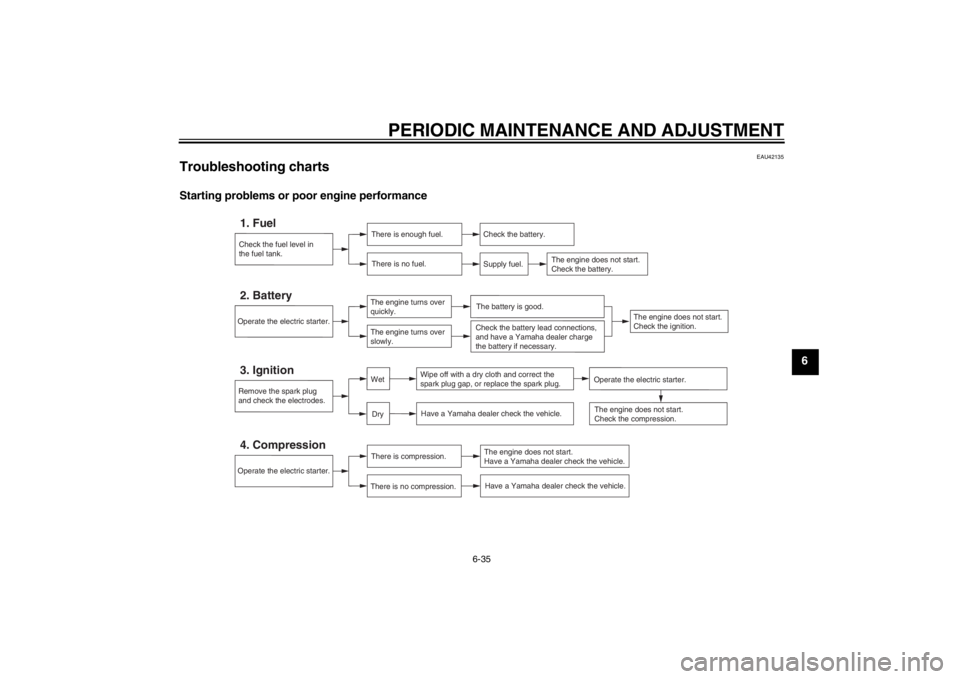
Troubleshooting charts Starting problems or poor engine performance
Check the fuel level in
the fuel tank.1. Fuel
There is enough fuel.
There is no fuel.
Check the battery.
Supply fuel.
The engine does not start.
Check the battery.
Operate the electric starter.4. Compression
There is compression.
There is no compression.
The engine does not start.
Have a Yamaha dealer check the vehicle.Have a Yamaha dealer check the vehicle.
Remove the spark plug
and check the electrodes.3. Ignition
Wipe off with a dry cloth and correct the
spark plug gap, or replace the spark plug.
Have a Yamaha dealer check the vehicle.
The engine does not start.
Check the compression.
Operate the electric starter.2. Battery
The engine turns over
quickly.
The engine turns over
slowly.
The battery is good.
DryWet
Operate the electric starter.
Check the battery lead connections,
and have a Yamaha dealer charge
the battery if necessary.
The engine does not start.
Check the ignition.
U2ABE2E0.book Page 35 Thursday, August 30, 2012 2:36 PM
Page 84 of 96
PERIODIC MAINTENANCE AND ADJUSTMENT
6-36
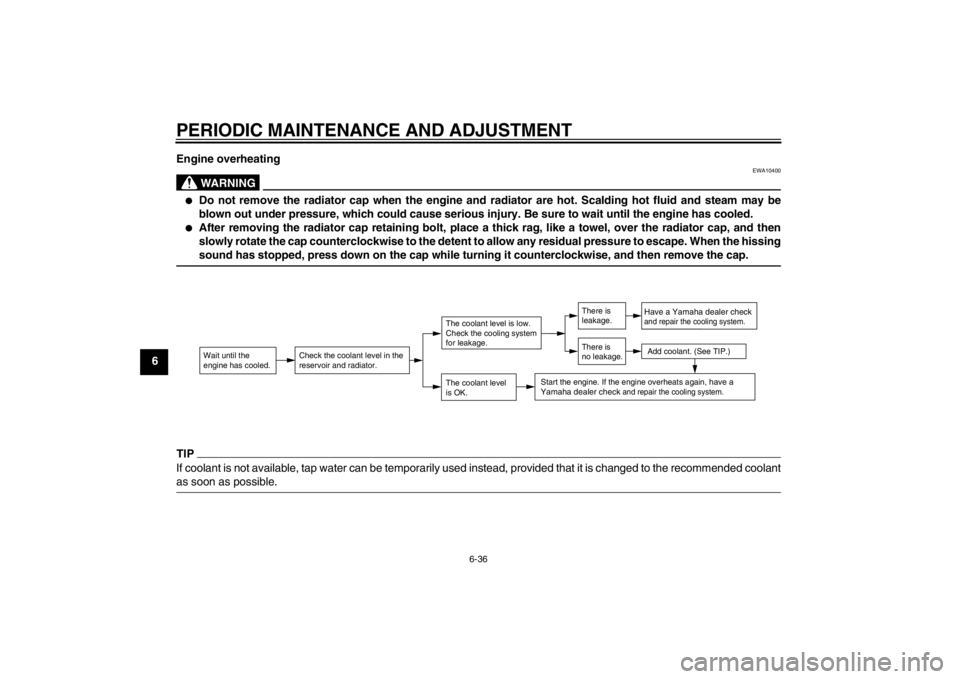
6Engine overheating
WARNING
EWA10400
●
Do not remove the radiator cap when the engine and radiator are hot. Scalding hot fluid and steam may be
blown out under pressure, which could cause serious injury. Be sure to wait until the engine has cooled.
●
After removing the radiator cap retaining bolt, place a thick rag, like a towel, over the radiator cap, and then
slowly rotate the cap counterclockwise to the detent to allow any residual pressure to escape. When the hissing
sound has stopped, press down on the cap while turning it counterclockwise, and then remove the cap.
TIPIf coolant is not available, tap water can be temporarily used instead, provided that it is changed to the recommended coolant
as soon as possible.
Wait until the
engine has cooled.
Check the coolant level in the
reservoir and radiator.
The coolant level
is OK.The coolant level is low.
Check the cooling system
for leakage.
Have a Yamaha dealer checkand repair the cooling system.Add coolant. (See TIP.)
Start the engine. If the engine overheats again,
have a
Yamaha dealer check
and repair the cooling system.
There is
leakage.
There is
no leakage.
U2ABE2E0.book Page 36 Thursday, August 30, 2012 2:36 PM
Page 88 of 96

SCOOTER CARE AND STORAGE
7-4
72. Fill up the fuel tank and add fuel
stabilizer (if available) to prevent
the fuel tank from rusting and the
fuel from deteriorating.
3. Perform the following steps to pro-
tect the cylinder, piston rings, etc.
from corrosion.
a. Remove the spark plug cap
and spark plug.
b. Pour a teaspoonful of engine oil
into the spark plug bore.
c. Install the spark plug cap onto
the spark plug, and then place
the spark plug on the cylinder
head so that the electrodes are
grounded. (This will limit spark-
ing during the next step.)
d. Turn the engine over several
times with the starter. (This will
coat the cylinder wall with oil.)
e. Remove the spark plug cap
from the spark plug, and then
install the spark plug and the
spark plug cap. WARNING! To
prevent damage or injury
from sparking, make sure to
ground the spark plug elec-
trodes while turning the en-
gine over.
[EWA10951]
4. Lubricate all control cables and the
pivoting points of all levers and
pedals as well as of the side-
stand/centerstand.
5. Check and, if necessary, correct
the tire air pressure, and then lift
the scooter so that both of its
wheels are off the ground. Alterna-
tively, turn the wheels a little every
month in order to prevent the tires
from becoming degraded in one
spot.
6. Cover the muffler outlet with a
plastic bag to prevent moisture
from entering it.
7. Remove the battery and fully
charge it. Store it in a cool, dry
place and charge it once a month.
Do not store the battery in an ex-
cessively cold or warm place [less
than 0 °C (30 °F) or more than 30
°C (90 °F)]. For more information
on storing the battery, see page
6-27.TIPMake any necessary repairs before
storing the scooter.
U2ABE2E0.book Page 4 Thursday, August 30, 2012 2:36 PM
Page 93 of 96

INDEX
AABS (for ABS models) .......................... 3-13
ABS warning light (for ABS models) ....... 3-4
Acceleration and deceleration ................ 5-3
Air filter and V-belt case air filter
elements ............................................. 6-16
Anti-theft alarm (optional) ..................... 3-11
Auxiliary DC jack .................................. 3-23
Auxiliary light bulb, replacing ................ 6-33BBattery .................................................. 6-27
Brake fluid, changing ............................ 6-24
Brake fluid level, checking .................... 6-22
Brake lever, front .................................. 3-12
Brake lever, rear ................................... 3-13
Brake levers, lubricating ....................... 6-25
Braking ................................................... 5-3CCables, checking and lubricating .......... 6-24
Care ........................................................ 7-1
Catalytic converters .............................. 3-16
Centerstand and sidestand,
checking and lubricating ..................... 6-25
Coolant ................................................. 6-14
Cowling and panel,
removing and installing......................... 6-8DDimmer switch ...................................... 3-12EEngine break-in ...................................... 5-4
Engine oil .............................................. 6-10
Engine trouble warning light ................... 3-4FFinal transmission oil ............................ 6-13Front and rear brake lever free play,
checking .............................................. 6-21
Front and rear brake pads, checking .... 6-21
Front fork, checking...............................6-26
Fuel ....................................................... 3-15
Fuel consumption, tips for reducing ........ 5-4
Fuel tank cap......................................... 3-14
Fuses, replacing .................................... 6-29
HHandlebar switches ............................... 3-11
Hazard switch........................................ 3-12
Headlight bulb, replacing....................... 6-30
High beam indicator light......................... 3-4
Horn switch ........................................... 3-12IIdentification numbers ............................. 9-1
Ignition circuit cut-off system ................. 3-21
Immobilizer system .................................3-1
Immobilizer system indicator light ........... 3-5
Indicator lights and warning lights ........... 3-4LLicense plate light .................................6-33MMain switch/steering lock ........................ 3-2
Maintenance and lubrication, periodic..... 6-4
Maintenance, emission control system ... 6-3
Matte color, caution .................................7-1
Model label .............................................. 9-1
Multi-function display...............................3-6PParking ....................................................5-5
Part locations .......................................... 2-1
Pass switch ........................................... 3-12
SSafe-riding points .................................... 1-5
Safety information ................................... 1-1
Seat ...................................................... 3-17
Securing bracket ................................... 3-17
Shock absorber assemblies,
adjusting ............................................. 3-20
Sidestand .............................................. 3-21
Spark plug, checking .............................. 6-9
Specifications.......................................... 8-1
Speedometer .......................................... 3-5
Starting off .............................................. 5-2
Starting the engine.................................. 5-1
Start switch ........................................... 3-12
Steering, checking ................................ 6-27
Storage ................................................... 7-3
Storage compartments ......................... 3-18TTachometer............................................. 3-6
Tail/brake light bulb or
rear turn signal light bulb, replacing.... 6-31
Throttle grip and cable,
checking and lubricating ..................... 6-24
Throttle grip free play, adjusting ........... 6-17
Tires ...................................................... 6-18
Tool kit .................................................... 6-2
Travel trunk ........................................... 3-19
Troubleshooting .................................... 6-33
Troubleshooting charts ......................... 6-35
Turn signal indicator lights ...................... 3-4
Turn signal light bulb (front),
replacing ............................................. 6-31
Turn signal switch ................................. 3-12
U2ABE2E0.book Page 1 Thursday, August 30, 2012 2:36 PM