seat adjustment YAMAHA XMAX 400 2020 Owners Manual
[x] Cancel search | Manufacturer: YAMAHA, Model Year: 2020, Model line: XMAX 400, Model: YAMAHA XMAX 400 2020Pages: 118, PDF Size: 9.04 MB
Page 66 of 118

Periodic maintenance and adjustment
7-2
7
EAU17303
Emission controls not only function to
ensure cleaner air, but are also vital to
proper engine operation and maximum
performance. In the following periodic
maintenance charts, the services relat-
ed to emissions control are grouped
separately. These services require
specialized data, knowledge, and
equipment. Maintenance, replace-
ment, or repair of the emission control
devices and systems may be per-
formed by any repair establishment or
individual that is certified (if applicable).
Yamaha dealers are trained and
equipped to perform these particular
services.
EAU79250
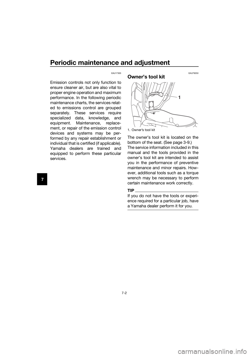
Owner’s tool kit
The owner’s tool kit is located on the
bottom of the seat. (See page 3-9.)
The service information included in this
manual and the tools provided in the
owner’s tool kit are intended to assist
you in the performance of preventive
maintenance and minor repairs. How-
ever, additional tools such as a torque
wrench may be necessary to perform
certain maintenance work correctly.
TIP
If you do not have the tools or experi-
ence required for a particular job, have
a Yamaha dealer perform it for you.
1.
1
UBL1E0E0.book Page 2 Thursday, May 11, 2017 8:51 AM
Page 75 of 118
![YAMAHA XMAX 400 2020 Owners Manual Periodic maintenance and adjustment
7-11
7 ment cover, the compression
spring will fall out. Take care not
to lose the compression spring.
[ECA12912]
6. Remove and replace the oil filter
element and O YAMAHA XMAX 400 2020 Owners Manual Periodic maintenance and adjustment
7-11
7 ment cover, the compression
spring will fall out. Take care not
to lose the compression spring.
[ECA12912]
6. Remove and replace the oil filter
element and O](/img/51/52977/w960_52977-74.png)
Periodic maintenance and adjustment
7-11
7 ment cover, the compression
spring will fall out. Take care not
to lose the compression spring.
[ECA12912]
6. Remove and replace the oil filter
element and O-rings.
7. Install the compression spring and
oil filter element cover by installing
the bolts, then tightening them to
the specified torque.
TIP
Make sure that the O-rings are properly
seated.
8. Install the engine oil drain bolt and
its new gasket, and then tighten
the bolt to the specified torque.
9. Refill with the specified amount of
the recommended engine oil, and
then install and tighten the oil filler
cap.
TIP
Be sure to wipe off spilled oil on any
parts after the engine and exhaust sys-
tem have cooled down.
NOTICE
ECA11671
Do not use oils with a diesel
specification of “CD” or oils of a
higher quality than specified. In
addition, do not use oils labeled
“ENERGY CONSERVING II” or
higher.
Be sure no foreign material en-
ters the crankcase.
1. Bolt
2. Oil filter element cover
1. Oil filter element cover
2. O-ring
3. Compression spring
4. Oil filter element
Tightening torque:
Oil filter element cover bolt:
10 N·m (1.0 kgf·m, 7.4 lb·ft)
21
12
43
Tightening torque:
Engine oil drain bolt:
20 N·m (2.0 kgf·m, 15 lb·ft)
Recommended engine oil:
See page 9-1.
Oil quantity:
Oil change:
1.50 L (1.59 US qt, 1.32 Imp.qt)
With oil filter removal:
1.70 L (1.80 US qt, 1.50 Imp.qt)
UBL1E0E0.book Page 11 Thursday, May 11, 2017 8:51 AM
Page 80 of 118

Periodic maintenance and adjustment
7-16
75. Install the air filter case cover by
installing the screws. NOTICE:
Make sure that each filter ele-
ment is properly seated in its
case. Always replace both air fil-
ter elements at the same time,
otherwise poor engine perfor-
mance or damage to the engine
may result. The engine should
never be operated without the
filter elements installed, other-
wise the piston(s) and/or cylin-
der(s) may become excessively
worn.
[ECA12924]
6. Install the rubber caps.
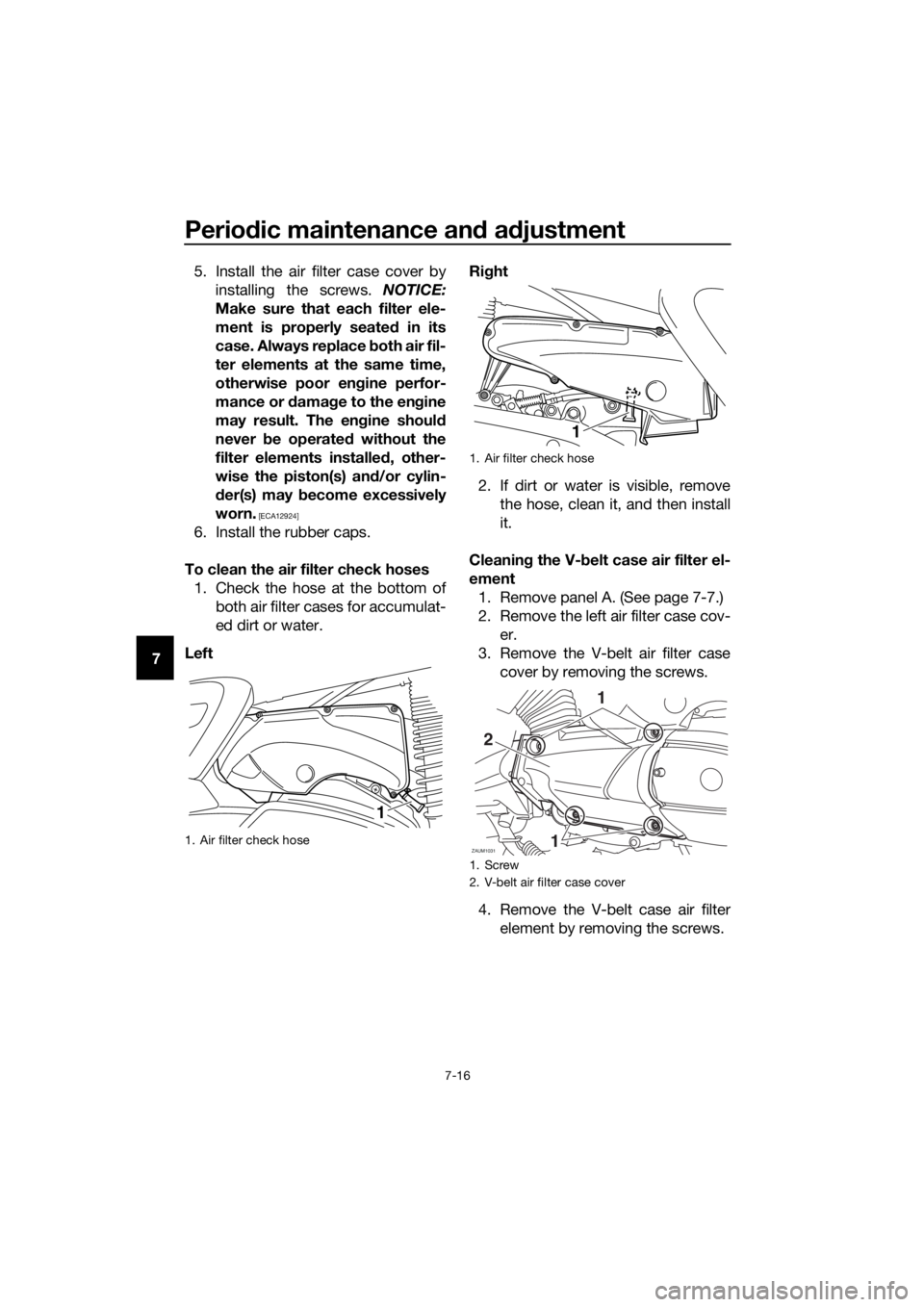
To clean the air filter check hoses
1. Check the hose at the bottom of
both air filter cases for accumulat-
ed dirt or water.
LeftRight
2. If dirt or water is visible, remove
the hose, clean it, and then install
it.
Cleaning the V-belt case air filter el-
ement
1. Remove panel A. (See page 7-7.)
2. Remove the left air filter case cov-
er.
3. Remove the V-belt air filter case
cover by removing the screws.
4. Remove the V-belt case air filter
element by removing the screws.
1. Air filter check hose
1
1. Air filter check hose
1. Screw
2. V-belt air filter case cover
1
ZAUM1031
2
11
UBL1E0E0.book Page 16 Thursday, May 11, 2017 8:51 AM
Page 81 of 118

Periodic maintenance and adjustment
7-17
7 5. Lightly tap the V-belt case air filter
element to remove most of the
dust and dirt, and then blow out
the dirt with compressed air as
shown.
6. Check the V-belt case air filter ele-
ment for damage and replace it if
necessary.
7. Install the V-belt case air filter ele-
ment by installing the screws.
NOTICE: Make sure that the V-
belt filter element is properly
seated in its case.
[ECA12942]
8. Install the V-belt air filter case cov-
er by installing the screws.
9. Install the left air filter case cover.
10. Install the panel.
EAU21386
Checking the throttle grip free
play
Measure the throttle grip free play as
shown.
Periodically check the throttle grip free
play and, if necessary, have a Yamaha
dealer adjust it.
1. Screw
2. V-belt case air filter element
2
1 1
1. Throttle grip free play
Throttle grip free play:
3.0–5.0 mm (0.12–0.20 in)
UBL1E0E0.book Page 17 Thursday, May 11, 2017 8:51 AM