height YAMAHA YZ125LC 2001 Owners Manual
[x] Cancel search | Manufacturer: YAMAHA, Model Year: 2001, Model line: YZ125LC, Model: YAMAHA YZ125LC 2001Pages: 558, PDF Size: 13.11 MB
Page 68 of 558

2-1
SPECGENERAL SPECIFICATIONS
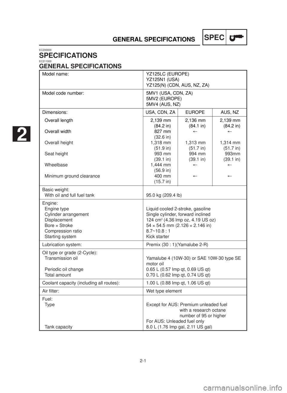
Model name: YZ125LC (EUROPE)
YZ125N1 (USA)
YZ125(N) (CDN, AUS, NZ, ZA)
Model code number: 5MV1 (USA, CDN, ZA)
5MV2 (EUROPE)
5MV4 (AUS, NZ)
Dimensions:USA, CDN, ZAEUROPE AUS, NZ
Overall length 2,139 mm 2,136 mm 2,139 mm
(84.2 in) (84.1 in) (84.2 in)
Overall width 827 mm¬¬
(32.6 in)
Overall height 1,318 mm 1,313 mm 1,314 mm
(51.9 in) (51.7 in) (51.7 in)
Seat height 993 mm 994 mm 993mm
(39.1 in) (39.1 in) (39.1 in)
Wheelbase 1,444 mm¬¬
(56.9 in)
Minimum ground clearance 400 mm¬¬
(15.7 in)
Basic weight:
With oil and full fuel tank 95.0 kg (209.4 lb)
Engine:
Engine type Liquid cooled 2-stroke, gasoline
Cylinder arrangement Single cylinder, forward inclined
Displacement 124 cm
3(4.36 lmp oz, 4.19 US oz)
Bore ´Stroke 54 ´54.5 mm (2.126 ´2.146 in)
Compression ratio 8.7~10.8 : 1
Starting system Kick starter
Lubrication system: Premix (30 : 1)(Yamalube 2-R)
Oil type or grade (2-Cycle):
Transmission oil Yamalube 4 (10W-30) or SAE 10W-30 type SE
motor oil
Periodic oil change 0.65 L (0.57 Imp qt, 0.69 US qt)
Total amount 0.70 L (0.62 Imp qt, 0.74 US qt)
Coolant capacity (including all routes): 1.00 L (0.88 Imp qt, 1.06 US qt)
Air filter: Wet type element
Fuel:
Type Except for AUS: Premium unleaded fuel
with a research octane
number of 95 or higher
For AUS: Unleaded fuel only
Tank capacity 8.0 L (1.76 Imp gal, 2.11 US gal)
EC200000
SPECIFICATIONSEC211000
GENERAL SPECIFICATIONS
2
5MV-9-30-2A 6/19/00 1:15 PM Page 2
Page 71 of 558

2-4
SPECMAINTENANCE SPECIFICATIONS
Item Standard Limit
Transmission:
Main axle deflection limit…
0.01 mm (0.0004 in)
Drive axle deflection limit…
0.01 mm (0.0004 in)
Shifter:
Shifting type Cam drum and guide bar…
Guide bar bending limit…
0.05 mm (0.0020 in)
Kick starter type: Kick and mesh type…
Kick clip friction force P=0.8~1.2 kg (1.8~2.6 lb)…
Air filter oil grade (oiled filter):Foam-air-filter oil or engine mixing oil…
Carburetor: USA, CDN, ZA
EUROPE
AUS, NZ
Type/Manufacturer TMXø
38SS¬
/MIKUNI
I.D. mark 5MV1 00 5MV2 10…
Main jet (M.J.) #460 #450…
Jet needle-clip position (J.N.) 6BGK9-75-3 6BHY1-75-3…
Cutaway (C.A.) 5.75¬…
Pilot jet (P.J.) #25 #30…
Pilot air screw (P.A.S.) 1-1/4 1-1/2…
Valve seat size (V.S.)
ø3.8 mm (0.15 in)¬…
Starter jet (G.S.) #80¬…
Fuel level (F.L.) 13.5~14.5 mm ¬
(0.53~0.57 in)
Reed valve:
Thickness* 0.42 mm (0.017 in)…
Valve stopper height 8.2~8.6 mm (0.323~0.339 in)…
Valve bending limit…
0.2 mm (0.008 in)
Cooling:
Radiator core size:
Width 110 mm (4.33 in)…
Height (left) 240 mm (9.45 in)…
(right) 220 mm (8.66 in)…
Thickness 32 mm (1.26 in)…
Radiator cap opening pressure 95~125 kPa…
(0.95~1.25 kg/cm
2, 13.5~17.8 psi)
Radiator capacity (total) 0.63 L (0.55 Imp qt, 0.67 US qt)…
Water pump:
Type Single-suction centrifugal pump…
5MV-9-30-2A 6/19/00 1:15 PM Page 5
Page 75 of 558

2-8
SPECMAINTENANCE SPECIFICATIONS
Item Standard Limit
Wheel:
Front wheel type Spoke wheel…
Rear wheel type Spoke wheel…
Front rim size/Material 21 ´1.60/Aluminum…
Rear rim size/Material 19 ´1.85/Aluminum…
Rim runout limit:
Radial…
2.0 mm (0.08 in)
Lateral … 2.0 mm (0.08 in)
Drive chain:
Type/Manufacturer DID520DMA2 SDH/DAIDO …
Number of links 111 links+joint …
Chain slack 40~50 mm (1.6~2.0 in) …
Chain length (10 links) … 152.5 mm (6.004 in)
Front disc brake:
Disc outside dia. ´Thickness 250 ´3.0 mm (9.84 ´0.12 in)…
Pad thickness 4.4 mm (0.17 in) 1.0 mm (0.04 in)
Master cylinder inside dia. 11.0 mm (0.433 in)…
Caliper cylinder inside dia. 27.0 mm (1.063 in) ´2…
Brake fluid type DOT #4…
Rear disc brake:
Disc outside dia. ´Thickness 240 ´4.0 mm (9.45 ´0.16 in)…
Deflection limit…
0.15 mm (0.006 in)
Pad thickness 6.4 mm (0.25 in) 1.0 mm (0.04 in)
Master cylinder inside dia. 12.7 mm (0.500 in)…
Caliper cylinder insdie dia. 27.0 mm (1.063 in)…
Brake fluid type DOT #4…
Brake lever & brake pedal:
Brake lever position 95 mm (3.74 in)…
Brake pedal height 5 mm (0.20 in)…
(vertical height above footrest top)
Clutch lever free play (at lever pivot) 2~4 mm (0.08~0.16 in)…
Throttle grip free play 3~5 mm (0.12~0.20 in)…
5MV-9-30-2A 6/19/00 1:15 PM Page 9
Page 123 of 558

3-2
MAINTENANCE INTERVALS
INSP
ADJ
Item Remarks
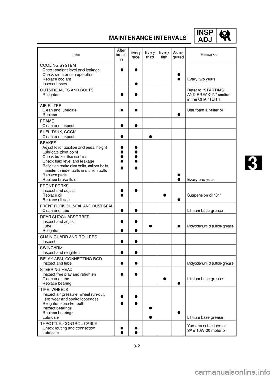
COOLING SYSTEM
Check coolant level and leakagell
Check radiator cap operationl
Replace coolantlEvery two years
Inspect hosesl
OUTSIDE NUTS AND BOLTS Refer to “STARTING
RetightenllAND BREAK-IN” section
in the CHAPTER 1.
AIR FILTER
Clean and lubricatellUse foam air-filter oil
Replacel
FRAME
Clean and inspectll
FUEL TANK, COCK
Clean and inspectll
BRAKES
Adjust lever position and pedal heightll
Lubricate pivot pointll
Check brake disc surfacell
Check fluid level and leakagell
Retighten brake disc bolts, caliper bolts,
ll
master cylinder bolts and union bolts
Replace padsl
Replace brake fluidlEvery one year
FRONT FORKS
Inspect and adjustll
Replace oilllSuspension oil “01”
Replace oil seall
FRONT FORK OIL SEAL AND DUST SEAL
Clean and lubellLithium base grease
REAR SHOCK ABSORBER
Inspect and adjustll
Lube ll
Molybdenum disulfide grease
Retightenll
CHAIN GUARD AND ROLLERS
Inspectll
SWINGARM
Inspect and retightenll
RELAY ARM, CONNECTING ROD
Inspect and lubellMolybdenum disulfide grease
STEERING HEAD
Inspect free play and retightenll
Clean and lubelLithium base grease
Replace bearingl
TIRE, WHEELS
Inspect air pressure, wheel run-out,
ll
tire wear and spoke looseness
Retighten sprocket boltll
Inspect bearingsl
Replace bearingsl
LubricatelLithium base grease
THROTTLE, CONTROL CABLE
Check routing and connectionllYamaha cable lube or
LubricatellSAE 10W-30 motor oil
After
break-
inEvery
raceEvery
thirdEvery
fifthAs re-
quired
3
5MV-9-30-3A 6/19/00 1:52 PM Page 3
Page 166 of 558

3-19
REAR BRAKE ADJUSTMENT/
FRONT BRAKE PAD INSPECTION AND REPLACEMENTINSP
ADJ
EC365080
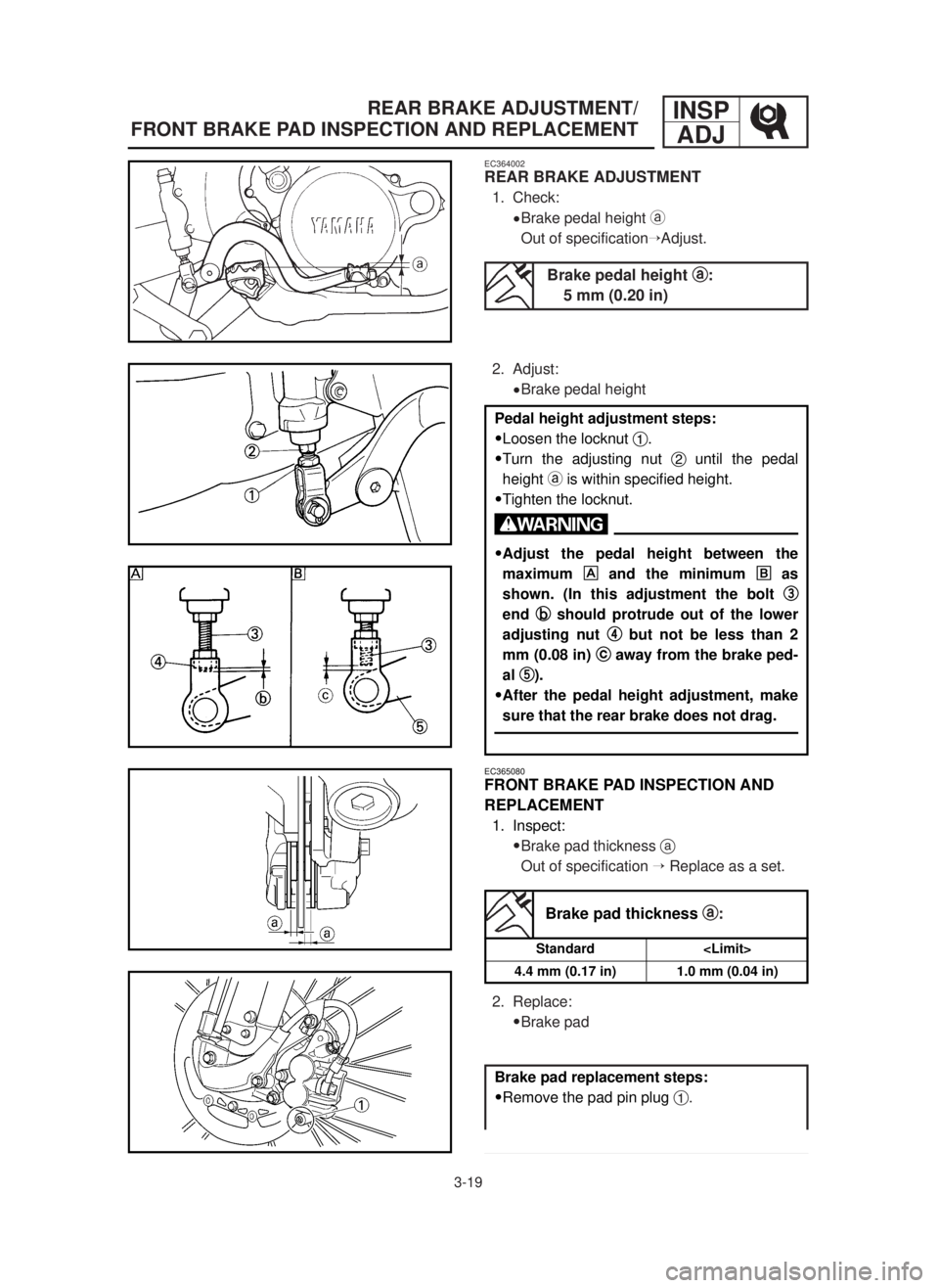
FRONT BRAKE PAD INSPECTION AND
REPLACEMENT
1. Inspect:
9Brake pad thickness a
Out of specification ÕReplace as a set.
2. Replace:
9Brake pad
Brake pad thickness a a
:
Standard
4.4 mm (0.17 in)
1.0 mm (0.04 in)
Brake pad replacement steps:
9Remove the pad pin plug 1.
EC364002
REAR BRAKE ADJUSTMENT
1. Check:
9Brake pedal height a
Out of specificationÕAdjust.
2. Adjust:
9Brake pedal height
Brake pedal height a a
:
5 mm (0.20 in)
Pedal height adjustment steps:
9Loosen the locknut 1.
9Turn the adjusting nut 2until the pedal
height ais within specified height.
9Tighten the locknut.
w
9Adjust the pedal height between the
maximum
and the minimum õ õ
as
shown. (In this adjustment the bolt 3 3
end b b
should protrude out of the lower
adjusting nut 4 4
but not be less than 2
mm (0.08 in) c c
away from the brake ped-
al 5 5
).
9After the pedal height adjustment, make
sure that the rear brake does not drag.
5MV-9-30-3B 6/19/00 1:49 PM Page 2
Page 232 of 558

4-12
ENGCARBURETOR AND REED VALVE
9Valve stopper height b
Out of specification ÕAdjust stopper/
Replace valve stopper.
EC465000
ASSEMBLY AND INSTALLATION
EC465190
Reed valve
1. Install:
9Reed valve 1
9Stopper (reed valve) 2
9Screw (reed valve) 3
NOTE:
9Install the reed valve with the reed valve bend-
ing as shown.
9Note the cut ain the lower corner of the reed
and stopper plate.
cC
Tighten each screw gradually to avoid
warping.
Valve stopper height:
8.2 ~8.6 mm (0.323~0.339 in)
1 Nm (0.1 m•kg, 0.7 ft•lb)
EC464600
Float
1. Inspect:
9Float 1
Damage ÕReplace.
EC464701
Reed valve
1. Measure:
9Reed valve bending a
Out of specification ÕReplace.
Reed valve bending limit:
0.2 mm (0.008 in)
5MV-9-30-4A 6/19/00 1:47 PM Page 24
Page 400 of 558

5-23
CHASFRONT BRAKE AND REAR BRAKE
EC5A5911
Front brake hose
1. Install:
9Brake hose 1
To brake hose holder 2.
NOTE:
Before tightening the bolt (brake hose holder),
align the top aof the brake hose neck with the
brake hose holder bottom b. Then pass the
brake hose in front of the axle boss cand fit it
into the hose groove dso that the brake hose
does not contact the nut (wheel axle).
2. Install:
9Hose cover 1
9Plain washer 2
9Bolt [hose cover (M8)] 3
9Bolt [hose cover (M6)] 4
10 Nm (1.0 m•kg, 7.2 ft•lb)
16 Nm (1.6 m•kg, 11 ft•lb)
7 Nm (0.7 m•kg, 5.1 ft•lb)
4. Install:
9Pin 1
9Plain washer 2
9Cotter pin 3
NOTE:
After installing, check the brake pedal height.
Refer to “REAR BRAKE ADJUSTMENT” section
in the CHAPTER 3.
3. Pass the brake hose through the cable
guide 1, then through the guide aon the
protector 2.
5MV-9-30-5A 6/19/00 1:36 PM Page 46