engine YAMAHA YZ125LC 2005 Notices Demploi (in French)
[x] Cancel search | Manufacturer: YAMAHA, Model Year: 2005, Model line: YZ125LC, Model: YAMAHA YZ125LC 2005Pages: 568, PDF Size: 12.99 MB
Page 382 of 568
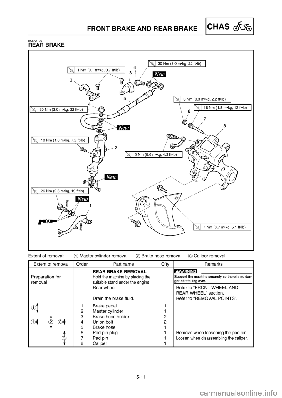
5-11
CHASFRONT BRAKE AND REAR BRAKE
EC5A8100
REAR BRAKE
Extent of removal Order Part name Q’ty Remarks
REAR BRAKE REMOVAL
Preparation for
Hold the machine by placing the
removalsuitable stand under the engine.
Rear wheel Refer to “FRONT WHEEL AND
REAR WHEEL” section.
Drain the brake fluid. Refer to “REMOVAL POINTS”.
1 Brake pedal 1
2 Master cylinder 1
3 Brake hose holder 2
4 Union bolt 2
5 Brake hose 1
6 Pad pin plug 1
Remove when loosening the pad pin.
7 Pad pin 1Loosen when disassembling the caliper.
8 Caliper 1
Extent of removal:1Master cylinder removal2Brake hose removal3Caliper removal
w
Support the machine securely so there is no dan-
ger of it falling over.
2
3
31
1
1 Nm (0.1 m•kg, 0.7 ft•lb)
30 Nm (3.0 m•kg, 22 ft•lb)
30 Nm (3.0 m•kg, 22 ft•lb)
3 Nm (0.3 m•kg, 2.2 ft•lb)
18 Nm (1.8 m•kg, 13 ft•lb)
6 Nm (0.6 m•kg, 4.3 ft•lb)
26 Nm (2.6 m•kg, 19 ft•lb)
10 Nm (1.0 m•kg, 7.2 ft•lb)
7 Nm (0.7 m•kg, 5.1 ft•lb)
1C3-9-30-5A 17/5/04 1:41 PM Page 22
Page 412 of 568
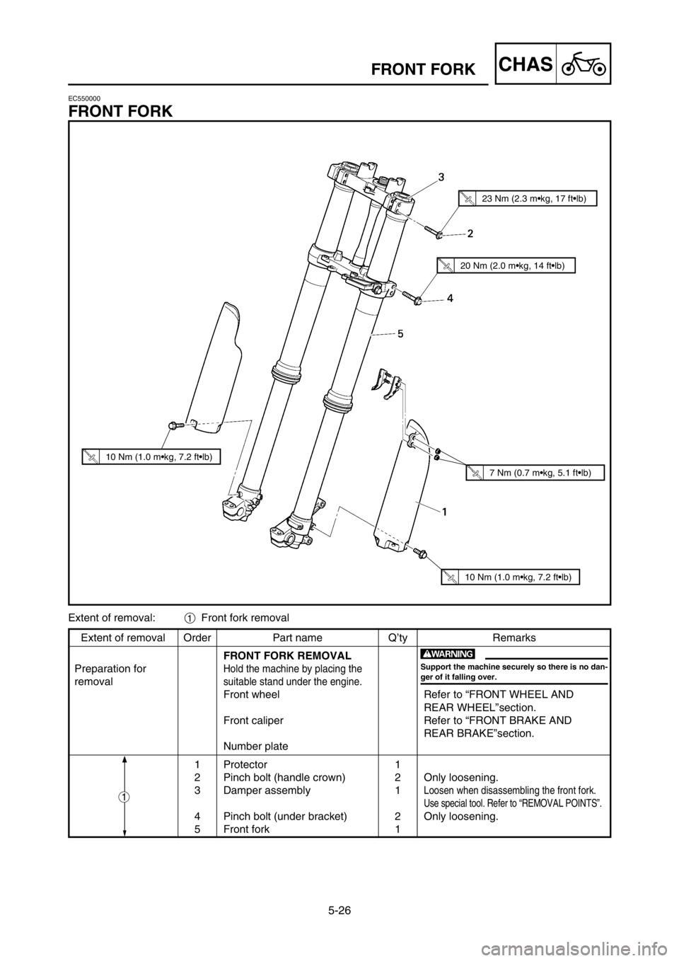
5-26
CHASFRONT FORK
Extent of removal Order Part name Q’ty Remarks
FRONT FORK REMOVAL
Preparation for
Hold the machine by placing the
removalsuitable stand under the engine.
Front wheel Refer to “FRONT WHEEL AND
REAR WHEEL”section.
Front caliper Refer to “FRONT BRAKE AND
REAR BRAKE”section.
Number plate
1 Protector 1
2 Pinch bolt (handle crown) 2 Only loosening.
3 Damper assembly 1
Loosen when disassembling the front fork.
Use special tool. Refer to “REMOVAL POINTS”.
4 Pinch bolt (under bracket) 2 Only loosening.
5 Front fork 1
1
w
Support the machine securely so there is no dan-
ger of it falling over.
Extent of removal:1Front fork removal
10 Nm (1.0 m•kg, 7.2 ft•lb)
10 Nm (1.0 m•kg, 7.2 ft•lb)
7 Nm (0.7 m•kg, 5.1 ft•lb)
20 Nm (2.0 m•kg, 14 ft•lb)
23 Nm (2.3 m•kg, 17 ft•lb)
EC550000
FRONT FORK
1C3-9-30-5B 28/5/04 9:07 AM Page 2
Page 442 of 568
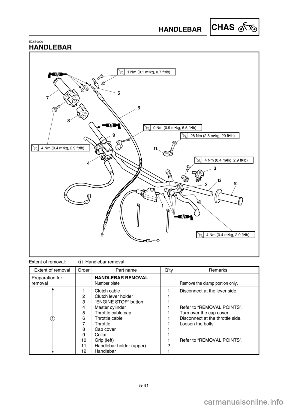
5-41
CHASHANDLEBAR
Extent of removal Order Part name Q’ty Remarks
Preparation forHANDLEBAR REMOVAL
removal
Number plate Remove the clamp portion only.
1 Clutch cable 1 Disconnect at the lever side.
2 Clutch lever holder 1
3 “ENGINE STOP” button 1
4 Master cylinder 1 Refer to “REMOVAL POINTS”.
5 Throttle cable cap 1 Turn over the cap cover.
6 Throttle cable 1 Disconnect at the throttle side.
7 Throttle 1 Loosen the bolts.
8 Cap cover 1
9 Collar 1
10 Grip (left) 1 Refer to “REMOVAL POINTS”.
11 Handlebar holder (upper) 2
12 Handlebar 1
EC5B0000
HANDLEBAR
1
Extent of removal:1Handlebar removal
1 Nm (0.1 m•kg, 0.7 ft•lb)
4 Nm (0.4 m•kg, 2.9 ft•lb)
9 Nm (0.9 m•kg, 6.5 ft•lb)
28 Nm (2.8 m•kg, 20 ft•lb)
4 Nm (0.4 m•kg, 2.9 ft•lb)
4 Nm (0.4 m•kg, 2.9 ft•lb)
1C3-9-30-5C 25/5/04 7:29 PM Page 2
Page 443 of 568

5-41
CHAS
GUIDON
LENKSTANGE
MANUBRIO
AusbauumfangReihen-
TeilenameStück-
Bemerkungen
folgezahl
AUSBAU DER LENKSTANGE
Nummernschild Nur das Klemmteil entfernen.
1 Kupplungskabel 1 An der Hebelseite abtrennen.
2 Kupplungshebelhalter 1
3 Motorstoppknopf „ENGINE STOP“ 1
4 Hauptbremszylinder 1 Siehe unter „AUSBAUPUNKTE“.
5 Gasseilkappe 1 Die Kappenabdeckung umkehren.
6 Gasseil 1 An der Gasdrehgriffseite abtrennen.
7 Gasderhgriff 1 Die Schrauben lösen.
8 Kappenabdeckung 1
9 Hülse 1
10 Griff (Links) 1 Siehe unter „AUSBAUPUNKTE“.
11 Lenkerhalter (Oben) 2
12 Lenkstange 1
LENKSTANGE
Ausbauumfang:1Ausbau der Lenkstange
GUIDON
Etendue de dépose:1Dépose du guidon
Etendue de dépose Ordre Nom de pièce Q’té Remarques
DEPOSE DU GUIDON
Plaque d’immatriculation Enlever seulement la partie de fixation.
1 Câble d’embrayage 1 Déconnecter du côté levier.
2 Support de levièr d’embrayage 1
3 Bouton d’arrêt du moteur 1
“ENGINE STOP”
4 Maître-cylindre 1 Se reporter à “POINTS DE DEPOSE”.
5 Capuchon du câble d’accélérateur 1 Retourner le couvercle de capuchon.
6 Câble d’accélérateur 1 Déconnecter du côté accélérateur.
7 Accélérateur 1 Desserrer les boulons.
8 Couvercle de capuchon 1
9 Collerette 1
10 Poignée (gauche) 1 Se reporter à “POINTS DE DEPOSE”.
11 Support de guidon (supérieur) 2
12 Guidon 1
Préparation
pour la dépose
IC5B0000
MANUBRIO
Ampiezza della rimozione:1Rimozione del manubrio
Ampiezza della rimozione Ordine Particolare Quantità Osservazione
RIMOZIONE DEL MANUBRIO
Targa Togliere soltanto la parte della brida.
1Cavo della frizione 1 Scollegare sul lato della leva2Supporto della leva di comando della 1
frizione
3Pulsante “ARRESTO MOTORE” 14Cilindro principale1 Consultare “PUNTI DI RIMOZIONE”.
5Calotta del cavo dell’acceleratore1 Ruotarlo sopra il coperchio della calotta.
6Cavo dell’acceleratore1 Scollegarlo sul lato dell’acceleratore.
7 Acceleratore 1 Allentare i bulloni.
8
Coperchio della calotta1
9Collare1
10Manopola (sinistra)1 Consultare “PUNTI DI RIMOZIONE”.
11Supporto del manubrio (superiore)2
12Manubrio1
Preparazione per
la rimozione
Vorbereitung
den Ausbau
1
1
1
1C3-9-30-5C 25/5/04 7:29 PM Page 3
Page 452 of 568

5-46
CHASHANDLEBAR
10. Install:
9Bolt (grip cap) 1
w
9Install the grip cap so that the gaps a a
and
b b
between the bolt (grip cap) and brake
lever 2 2
are equal. If you make a mistake in
the grip cap installation position, the brake
lever may contact the grip cap, resulting in
poor brake performance.
9After tightening the bolts, check that the
throttle grip 3 3
moves smoothly. If it does
not, retighten the bolts for adjustment.
11. Install:
9“ENGINE STOP” button 1
9Clutch lever holder 2
9Bolt (clutch lever holder) 3
9Clamp 4
NOTE:
9The “ENGINE STOP” button, clutch lever hold-
er and clamp should be installed according to
the dimensions shown.
9Pass the “ENGINE STOP” button lead in the
middle of the clutch holder.
4 Nm (0.4 m•kg, 2.9 ft•lb)
4 Nm (0.4 m•kg, 2.9 ft•lb)
9. Install:
9Master cylinder 1
9Master cylinder bracket 2
9Bolt (master cylinder bracket) 3
NOTE:
9Install the bracket so that the arrow mark a
faces upward.
9First tighten the bolt on the upper side of the
master cylinder bracket, and then tighten the
bolt on the lower side.
9 Nm (0.9 m•kg, 6.5 ft•lb)
1C3-9-30-5C 25/5/04 7:29 PM Page 12
Page 453 of 568

9. Einbauen:
9Hauptbremszylinder 1
9
Hauptbremszylinderhalterung
2
9
Schraube
(Hauptbremszylinderhalterung)
3
HINWEIS:
9Die Halterung so einbauen, daß die
Pfeilmarkierung anach oben ge-
richtet ist.
9
Zuerst die Schrauben an der Oberseite
der hauptbremszylinderhalterung und
danach die Schrauben an der
Unterseite festziehen.
9. Monter:
9Maître-cylindre 1
9Etrier de maître-cylindre 2
9Boulon (étrier de maître-cy-
lindre) 3
N.B.:
9Reposer la support pour que la flèche
asoit dirigée vers le haut.
9Serrer d’avord les boulons sur le côté
supérieur de l’étrier de maître-cy-
lindre, puis serrer les boulons sur le
côté inférieur.
5-46
CHAS
GUIDON
LENKSTANGE
MANUBRIO
10. Einbauen:
9Schraube (Griffkappe) 1
W
9Die Griffkappe so einbauen, daß
die Spalte a a
und b b
zwischen der
Schraube (Griffkappe) und dem
Bremschebel 2 2
gleich sind. Falls
die Griffkappe in falscher Position
eingebaut wird, kann der
Bremschebel die Griffkappe
berühren, so daß die Brems-
leistung verschlechtert wird.
9Nach dem Festziehen der
Schrauben darauf achten, daß
sich der Gasdrehgriff 3 3
glatt dre-
hen läßt. Ist dies nicht der Fall, die
Schrauben zur Einstellung
nochmals festziehen.
11. Einbauen:
9Motorstoppknopf „ENGINE
STOP “ 1
9Kupplungshebelhalter 2
9Schraube
(Kupplungshebelhalter) 3
9Klemme 4
HINWEIS:
9Motorausschalterknopf, Kupplungs-
hebelhalter und Klemme sollten un-
ter Einhaltung der angegebenen
Maße eingebaut werden.
9Das Leitungskabel des Motorstopp-
knopfes „ENGINE STOP” in der
Mitte des Kupplungshalters durch-
führen.
10. Monter:
9Boulon (capuchon de poignée)
1
XG
9Installer le capuchon de poignée de
sorte que les espaces a a
et b b
entre
le boulon (capuchon de poignée) et
le levier de frein 2 2
soient iden-
tiques. Si le capuchon de poignée est
mal positionné, le levier de frein
risque de toucher le capuchon de
poignée et la capacité de freinage
sera réduite.
9Après avoir serré les boulons, véri-
fier que la poignée d’accélérateur
3 3
tourne sans problème. Sinon res-
serrer les boulons pour la régler.
11. Monter:
9Bouton d’arrêt du moteur “EN-
GINE STOP” 1
9Support de levier d’embrayage
2
9Boulon (support de levier d’em-
brayage) 3
9Bride 4
N.B.:
9Le bouton d’arrêt du moteur “ENGI-
NE STOP”, le support et la bride de
levier d’embrayage doivent être ins-
tallés selon les dimensions indiquées.
9Faire passer le fil de bouton d’arrêt du
moteur “ENGINE STOP” au centre
du support d’embrayage.
10. Installare:
9Bullone (calotta della manopo-
la) 1
T
9Installare la calotta della manopola
in modo che le distanze a a
e b b
fra il
bullone (calotta della manopola) e
la leva di comando del freno 2 2
sia-
no uguali. Se si sbaglia la posizione
di installazione della calotta della
manopola, la leva di comando del
freno può toccare la calotta della
manopola, il che comporta uno
scarso rendimento frenante.
9Dopo avere serrato i bulloni, con-
trollare che la manopola dell’acce-
leratore 3 3
si muova senza diffi-
coltà. In caso contrario, riserrare i
bulloni per la regolazione.
11. Installare:
9Pulsante “ARRESTO MOTO-
RE” 1
9Supporto della leva di comando
della frizione 2
9Bullone (supporto della leva di
comando della frizione) 3
9Brida 4
NOTA:
• Il pulsante “ARRESTO MOTORE”, il
supporto della leva di comando della
frizione e la brida dovrebbero essere
installati secondo le dimensioni illu-
strate.
• Far passare il conduttore del pulsante
“ARRESTO MOTORE” nel mezzo
del supporto della frizione.
4 Nm (0,4 m•kg, 2,9 ft•lb)
4 Nm (0,4 m•kg, 2,9 ft•lb)
4 Nm (0,4 m•kg, 2,9 ft•lb)
4 Nm (0,4 m•kg, 2,9 ft•lb)4 Nm (0,4 m•kg, 2,9 ft•lb)4 Nm (0,4 m•kg, 2,9 ft•lb)
9 Nm (0,9 m•kg, 6,5 ft•lb)
9 Nm (0,9 m•kg, 6,5 ft•lb)
9. Installare:
9Cilindro principale 1
9Staffa del cilindro principale 2
9Bullone (staffa del cilindro prin-
cipale) 3
NOTA:
9Installare la staffa in modo che la
freccia asia rivolta verso l’alto.
9Serrare dapprima il bullone sul lato
superiore della staffa del cilindro prin-
cipale, e quindi serrare il bullone sul
lato inferiore.
9 Nm (0,9 m•kg, 6,5 ft•lb)
1C3-9-30-5C 25/5/04 7:29 PM Page 13
Page 456 of 568
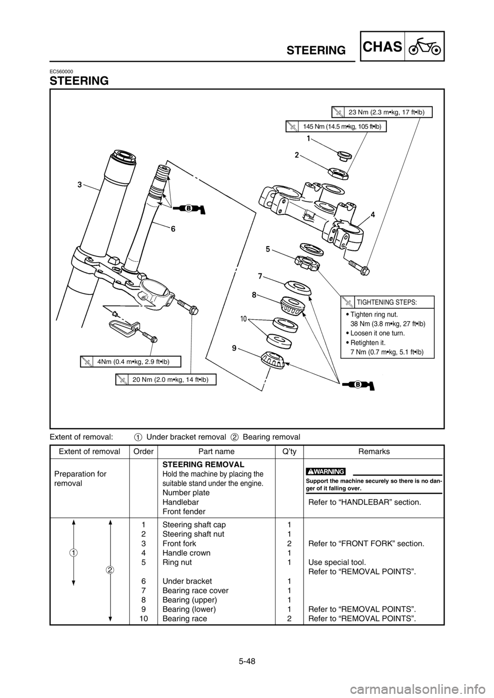
5-48
CHASSTEERING
Extent of removal Order Part name Q’ty Remarks
STEERING REMOVAL
Preparation for
Hold the machine by placing the
removalsuitable stand under the engine.
Number plate
Handlebar Refer to “HANDLEBAR” section.
Front fender
1 Steering shaft cap 1
2 Steering shaft nut 1
3 Front fork 2 Refer to “FRONT FORK” section.
4 Handle crown 1
5 Ring nut 1 Use special tool.
Refer to “REMOVAL POINTS”.
6 Under bracket 1
7 Bearing race cover 1
8 Bearing (upper) 1
9 Bearing (lower) 1 Refer to “REMOVAL POINTS”.
10 Bearing race 2 Refer to “REMOVAL POINTS”. Extent of removal:1Under bracket removal 2Bearing removal
2
1
w
Support the machine securely so there is no dan-
ger of it falling over.
EC560000
STEERING
145 Nm (14.5 m•kg, 105 ft•lb)
23 Nm (2.3 m•kg, 17 ft•lb)
9Tighten ring nut.
38 Nm (3.8 m•kg, 27 ft•lb)
9Loosen it one turn.
9Retighten it.
7 Nm (0.7 m•kg, 5.1 ft•lb)
TIGHTENING STEPS:
20 Nm (2.0 m•kg, 14 ft•lb)
4Nm (0.4 m•kg, 2.9 ft•lb)
1C3-9-30-5C 25/5/04 7:29 PM Page 16
Page 466 of 568
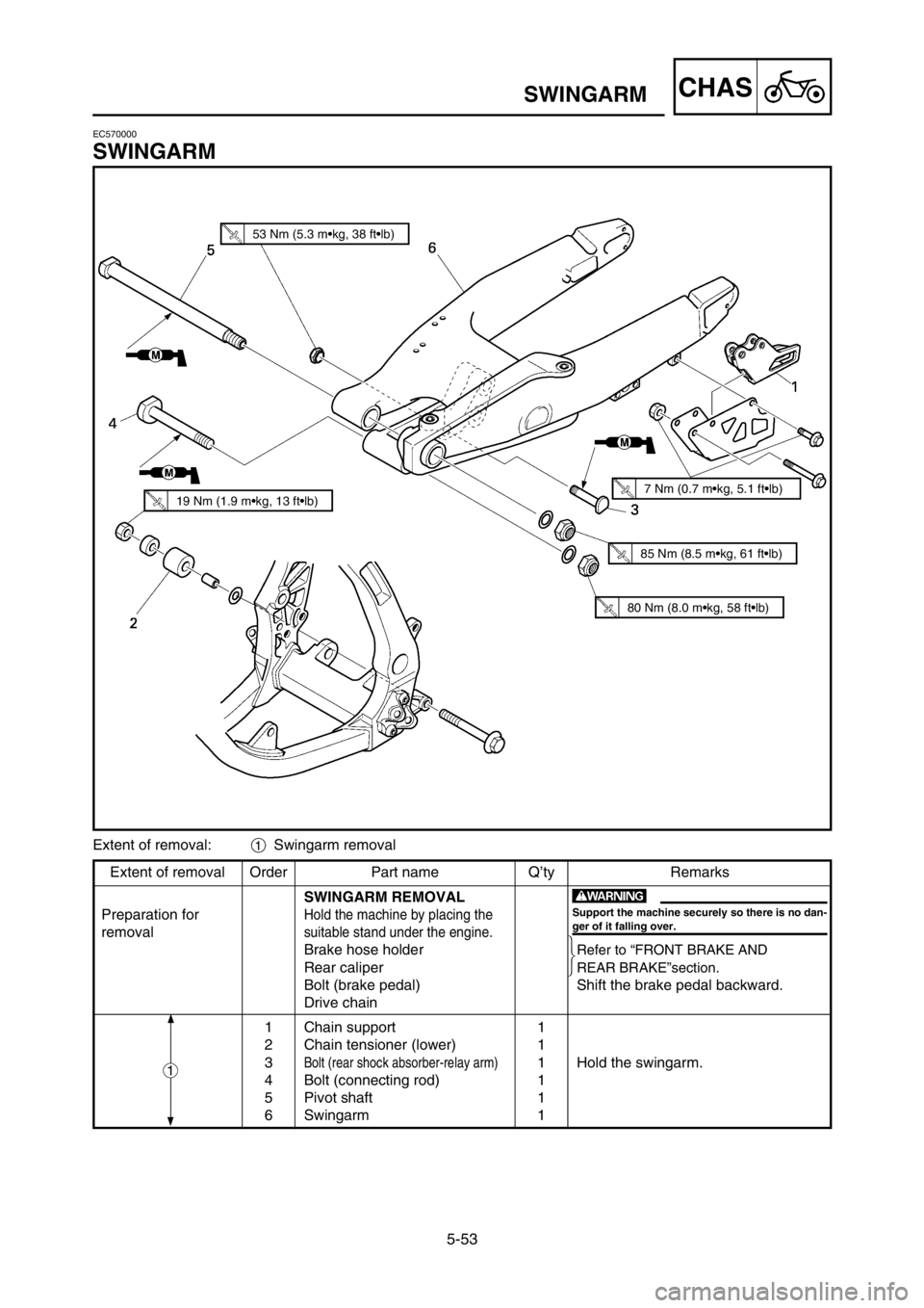
5-53
CHASSWINGARM
Extent of removal Order Part name Q’ty Remarks
SWINGARM REMOVAL
Preparation for
Hold the machine by placing the
removalsuitable stand under the engine.
Brake hose holderRefer to “FRONT BRAKE AND
Rear caliperREAR BRAKE”section.
Bolt (brake pedal) Shift the brake pedal backward.
Drive chain
1 Chain support 1
2 Chain tensioner (lower) 1
3
Bolt (rear shock absorber-relay arm)1 Hold the swingarm.
4 Bolt (connecting rod) 1
5 Pivot shaft 1
6 Swingarm 1 Extent of removal:
1Swingarm removal
1
w
Support the machine securely so there is no dan-
ger of it falling over.
EC570000
SWINGARM
53 Nm (5.3 m•kg, 38 ft•lb)
80 Nm (8.0 m•kg, 58 ft•lb)
19 Nm (1.9 m•kg, 13 ft•lb)7 Nm (0.7 m•kg, 5.1 ft•lb)
85 Nm (8.5 m•kg, 61 ft•lb)
1C3-9-30-5D 25/5/04 7:27 PM Page 2
Page 482 of 568
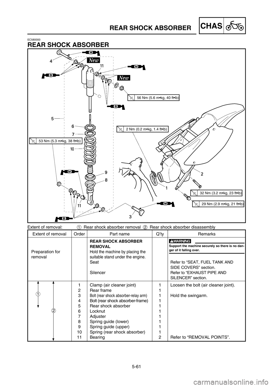
5-61
CHASREAR SHOCK ABSORBER
Extent of removal Order Part name Q’ty Remarks
REAR SHOCK ABSORBER
REMOVAL
Preparation forHold the machine by placing the
removalsuitable stand under the engine.
SeatRefer to “SEAT, FUEL TANK AND
SIDE COVERS” section.
SilencerRefer to “EXHAUST PIPE AND
SILENCER” section.
1 Clamp (air cleaner joint) 1 Loosen the bolt (air cleaner joint).
2 Rear frame 1
3
Bolt (rear shock absorber-relay arm)1 Hold the swingarm.
4 Bolt (rear shock absorber-frame) 1
5 Rear shock absorber 1
6 Locknut 1
7 Adjuster 1
8 Spring guide (lower) 1
9 Spring guide (upper) 1
10 Spring (rear shock absorber) 1
11 Bearing 2 Refer to “REMOVAL POINTS”.
2
w
Support the machine securely so there is no dan-
ger of it falling over.
Extent of removal:1Rear shock absorber removal 2Rear shock absorber disassembly
1
56 Nm (5.6 m•kg, 40 ft•lb)
53 Nm (5.3 m•kg, 38 ft•lb)
32 Nm (3.2 m•kg, 23 ft•lb)
EC580000
REAR SHOCK ABSORBER
29 Nm (2.9 m•kg, 21 ft•lb)
2 Nm (0.2 m•kg, 1.4 ft•lb)
1C3-9-30-5D 25/5/04 7:27 PM Page 18
Page 494 of 568

6-1
ELECELECTRICAL COMPONENTS AND WIRING DIAGRAM
EC600000
ELECTRICAL
EC610000
ELECTRICAL COMPONENTS AND WIRING DIAGRAM
EC611000
ELECTRICAL COMPONENTS
1“ENGINE STOP” button
2CDI unit
3Ignition coil
4CDI magneto
5Spark plug
EC612000
WIRING DIAGRAM
COLOR CODE
B...................Black
O ..................Orange
Y...................Yellow
B/R ...............Brack/Red
B/W ..............Black/White
G/L ..............Green/Blue
G/W ..............Green/White
W/L...............White/Blue
W/R ..............White/Red
1C3-9-30-6 14/5/04 5:47 PM Page 2