warning YAMAHA YZF-R1M 2015 Owner's Manual
[x] Cancel search | Manufacturer: YAMAHA, Model Year: 2015, Model line: YZF-R1M, Model: YAMAHA YZF-R1M 2015Pages: 126, PDF Size: 9.02 MB
Page 60 of 126
![YAMAHA YZF-R1M 2015 Owners Manual INSTRUMENT AND CONTROL FUNCTIONS
4-41
1
2
34
5
6
7
8
9
10
11
12 aging the couplers, do not use
sharp tools or excessive
force.
[ECA22770]
4. To increase the spring preload and
thereby harden the suspe YAMAHA YZF-R1M 2015 Owners Manual INSTRUMENT AND CONTROL FUNCTIONS
4-41
1
2
34
5
6
7
8
9
10
11
12 aging the couplers, do not use
sharp tools or excessive
force.
[ECA22770]
4. To increase the spring preload and
thereby harden the suspe](/img/51/54114/w960_54114-59.png)
INSTRUMENT AND CONTROL FUNCTIONS
4-41
1
2
34
5
6
7
8
9
10
11
12 aging the couplers, do not use
sharp tools or excessive
force.
[ECA22770]
4. To increase the spring preload and
thereby harden the suspension,
turn the adjusting bolt on each fork
leg in direction (a). To decrease
the spring preload and thereby
soften the suspension, turn the ad-
justing bolt on each fork leg in di-
rection (b). 5. Attach the coupler on each fork.
6. Slide the rubber cover to the origi-
nal position.
EAU66492
Adjusting the shock absorber
assembly
WARNING
EWA10222
This shock absorber assembly con-
tains highly pressurized nitrogen
gas. Read and understand the fol-
lowing information before handling
the shock absorber assembly.
Do not tamper with or attempt to
open the cylinder assembly.
Do not subject the shock ab-
sorber assembly to an open
flame or other high heat source.
This may cause the unit to ex-
plode due to excessive gas
pressure.
Do not deform or damage the
cylinder in any way. Cylinder
damage will result in poor
damping performance.
Do not dispose of a damaged or
worn-out shock absorber as-
sembly yourself. Take the shock
absorber assembly to a Yamahadealer for any service.
1. Rubber cover
2. Coupler
2
1
1. Spring preload adjusting boltSpring preload setting:Minimum (soft):
0 turn(s) in direction (a)*
Standard: 5 turn(s) in direction (a)*
Maximum (hard): 15 turn(s) in direction (a)*
* With the adjusting nut fully turned in
direction (b)
1
(a) (b)
2CR-9-E0_1.book 41 ページ 2015年1月5日 月曜日 午前11時54分
Page 64 of 126

INSTRUMENT AND CONTROL FUNCTIONS
4-45
1
2
34
5
6
7
8
9
10
11
12
EAU67050
EXUP systemThis model is equipped with Yamaha’s
EXUP (EXhaust Ultimate Power valve)
system. This system boosts engine
power by means of a valve that controls
exhaust flow within the exhaust cham-
ber.NOTICE
ECA15611
The EXUP system has been set and
extensively tested at the Yamaha
factory. Changing these settings
without sufficient technical knowl-
edge may result in poor perfor-mance of or damage to the engine.
EAU15306
SidestandThe sidestand is located on the left side
of the frame. Raise the sidestand or
lower it with your foot while holding the
vehicle upright.TIPThe built-in sidestand switch is part of
the ignition circuit cut-off system, which
cuts the ignition in certain situations.
(See the following section for an expla-
nation of the ignition circuit cut-off sys-tem.)
WARNING
EWA10242
The vehicle must not be ridden with
the sidestand down, or if the sides-
tand cannot be properly moved up
(or does not stay up), otherwise the
sidestand could contact the ground
and distract the operator, resulting
in a possible loss of control.
Yamaha’s ignition circuit cut-off
system has been designed to assist
the operator in fulfilling the respon-
sibility of raising the sidestand be-
fore starting off. Therefore, check
this system regularly and have a Yamaha dealer repair it if it does not
function properly.
2CR-9-E0_1.book 45 ページ 2015年1月5日 月曜日 午前11時54分
Page 66 of 126

INSTRUMENT AND CONTROL FUNCTIONS
4-47
1
2
34
5
6
7
8
9
10
11
12
With the engine turned off:
1. Move the sidestand down.
2. Make sure that the engine stop switch is set to “
3. Turn the key on.
4. Shift the transmission into the neutral position.
5. Push the start switch.
Does the engine start?
With the engine still running:
6. Move the sidestand up.
7. Keep the clutch lever pulled.
8. Shift the transmission into gear.
9. Move the sidestand down.
Does the engine stall?
After the engine has stalled:
10. Move the sidestand up.
11. Keep the clutch lever pulled.
12. Push the start switch.
Does the engine start?
The system is OK. The motorcycle can be ridden. The neutral switch may not be working correctly.
The motorcycle should not be ridden until
checked by a Yamaha dealer.
The sidestand switch may not be working correctly.
The motorcycle should not be ridden until
checked by a Yamaha dealer.
The clutch switch may not be working correctly.
The motorcycle should not be ridden until
checked by a Yamaha dealer.
YES NO YES NO YES NO
If a malfunction is noted, have a Yamaha
dealer check the system before riding.
WARNING
”.
2CR-9-E0_1.book 47 ページ 2015年1月5日 月曜日 午前11時54分
Page 67 of 126

INSTRUMENT AND CONTROL FUNCTIONS
4-48
1
2
345
6
7
8
9
10
11
12
EAU59950
Auxiliary DC connector
WARNING
EWA12532
To prevent electrical shock or
short-circuiting, make sure that the
cap is installed when the auxiliaryDC connector is not being used.NOTICE
ECA20090
The accessory connected to the
auxiliary DC connector should not
be used with the engine turned off,
and the load must never exceed 24
W (2 A), otherwise the fuse may blowor the battery may discharge. This vehicle is equipped with an auxilia-
ry DC connector. A 12–V accessory
connected to the auxiliary DC connec-
tor can be used when the key is in the
“ON” position.1. Auxiliary DC connector
2. Auxiliary DC connector cap21
2CR-9-E0_1.book 48 ページ 2015年1月5日 月曜日 午前11時54分
Page 68 of 126

5-1
1
2
3
45
6
7
8
9
10
11
12
FOR YOUR SAFETY – PRE-OPERATION CHECKS
EAU15599
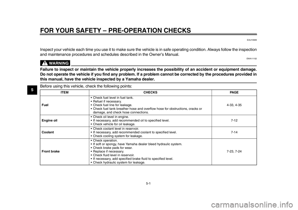
Inspect your vehicle each time you use it to make sure the vehi cle is in safe operating condition. Always follow the inspection
and maintenance procedures and schedules described in the Owner’s Manual.
WARNING
EWA11152
Failure to inspect or maintain the vehicle properly increases the possibility of an accident or equipment damage.
Do not operate the vehicle if you find any problem. If a problem cannot be corrected by the procedures provided inthis manual, have the vehicle inspected by a Yamaha dealer.
Before using this vehicle, check the following points:
ITEM CHECKS PAGE
Fuel Check fuel level in fuel tank.
Refuel if necessary.
Check fuel line for leakage.
Check fuel tank breather hose and overflow hose for obstructions, cracks or
damage, and check hose connections. 4-33, 4-35
Engine oil Check oil level in engine.
If necessary, add recommended oil to specified level.
Check vehicle for oil leakage. 7-12
Coolant Check coolant level in reservoir.
If necessary, add recommended coolant to specified level.
Check cooling system for leakage. 7-14
Front brake Check operation.
If soft or spongy, have Yamaha dealer bleed hydraulic system.
Check brake pads for wear.
Replace if necessary.
Check fluid level in reservoir.
If necessary, add specified brake fluid to specified level.
Check hydraulic system for leakage. 7-23, 7-24
2CR-9-E0_1.book 1 ページ 2015年1月5日 月曜日 午前11時54分
Page 71 of 126

6-1
1
2
3
4
567
8
9
10
11
12
OPERATION AND IMPORT ANT RIDING POINTS
EAU15952
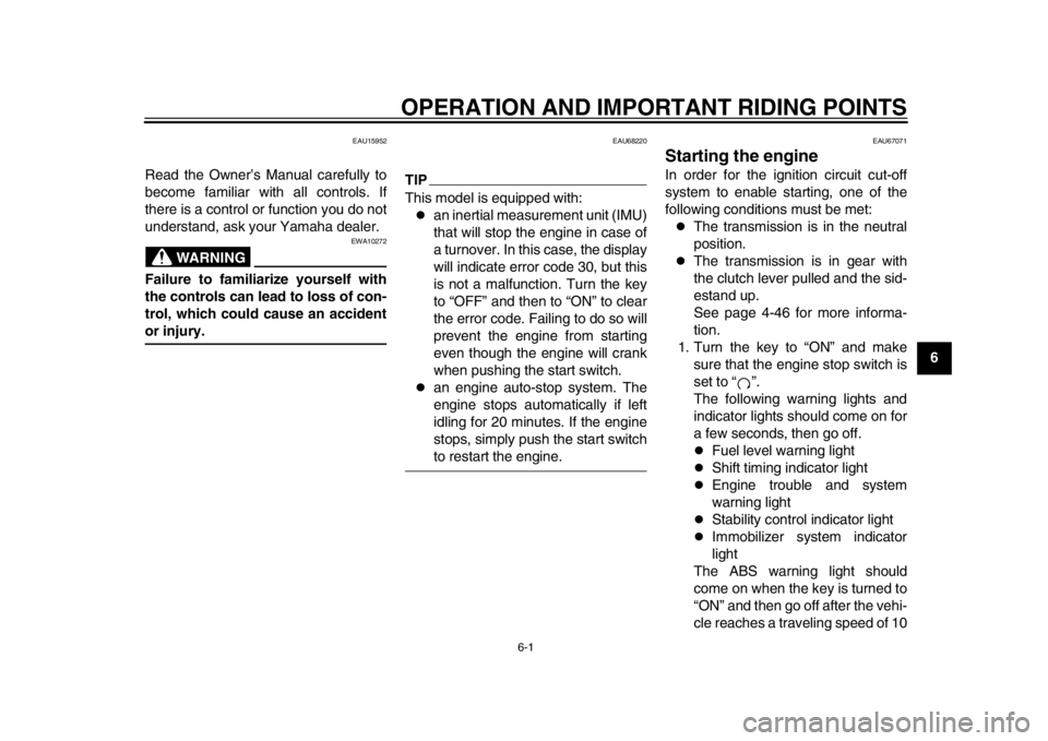
Read the Owner’s Manual carefully to
become familiar with all controls. If
there is a control or function you do not
understand, ask your Yamaha dealer.
WARNING
EWA10272
Failure to familiarize yourself with
the controls can lead to loss of con-
trol, which could cause an accidentor injury.
EAU68220
TIPThis model is equipped with:
an inertial measurement unit (IMU)
that will stop the engine in case of
a turnover. In this case, the display
will indicate error code 30, but this
is not a malfunction. Turn the key
to “OFF” and then to “ON” to clear
the error code. Failing to do so will
prevent the engine from starting
even though the engine will crank
when pushing the start switch.
an engine auto-stop system. The
engine stops automatically if left
idling for 20 minutes. If the engine
stops, simply push the start switchto restart the engine.
EAU67071
Starting the engineIn order for the ignition circuit cut-off
system to enable starting, one of the
following conditions must be met:
The transmission is in the neutral
position.
The transmission is in gear with
the clutch lever pulled and the sid-
estand up.
See page 4-46 for more informa-
tion.
1. Turn the key to “ON” and make sure that the engine stop switch is
set to “ ”.
The following warning lights and
indicator lights should come on for
a few seconds, then go off.
Fuel level warning light
Shift timing indicator light
Engine trouble and system
warning light
Stability control indicator light
Immobilizer system indicator
light
The ABS warning light should
come on when the key is turned to
“ON” and then go off after the vehi-
cle reaches a traveling speed of 10
2CR-9-E0_1.book 1 ページ 2015年1月5日 月曜日 午前11時54分
Page 72 of 126

OPERATION AND IMPORTANT RIDING POINTS
6-2
1
2
3
4
56
7
8
9
10
11
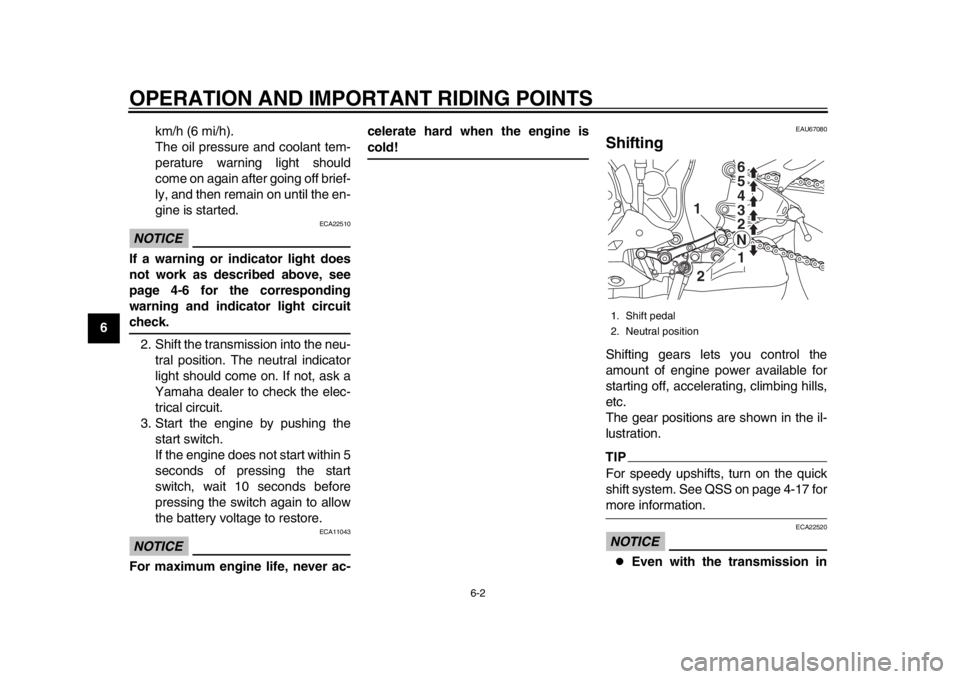
12 km/h (6 mi/h).
The oil pressure and coolant tem-
perature warning light should
come on again after going off brief-
ly, and then remain on until the en-
gine is started.
NOTICE
ECA22510
If a warning or indicator light does
not work as described above, see
page 4-6 for the corresponding
warning and indicator light circuitcheck.
2. Shift the transmission into the neu- tral position. The neutral indicator
light should come on. If not, ask a
Yamaha dealer to check the elec-
trical circuit.
3. Start the engine by pushing the start switch.
If the engine does not start within 5
seconds of pressing the start
switch, wait 10 seconds before
pressing the switch again to allow
the battery voltage to restore.NOTICE
ECA11043
For maximum engine life, never ac- celerate hard when the engine is
cold!
EAU67080
ShiftingShifting gears lets you control the
amount of engine power available for
starting off, accelerating, climbing hills,
etc.
The gear positions are shown in the il-
lustration.TIPFor speedy upshifts, turn on the quick
shift system. See QSS on page 4-17 formore information.NOTICE
ECA22520
Even with the transmission in
1. Shift pedal
2. Neutral position
1
1
2
2 3 4
5 6
N
2CR-9-E0_1.book 2 ページ 2015年1月5日 月曜日 午前11時54分
Page 75 of 126

OPERATION AND IMPORTANT RIDING POINTS
6-5
1
2
3
4
567
8
9
10
11
12
EAU17214
ParkingWhen parking, stop the engine, and
then remove the key from the main
switch.
WARNING
EWA10312
Since the engine and exhaust
system can become very hot,
park in a place where pedestri-
ans or children are not likely to
touch them and be burned.
Do not park on a slope or on soft
ground, otherwise the vehicle
may overturn, increasing the
risk of a fuel leak and fire.
Do not park near grass or other
flammable materials whichmight catch fire.
2CR-9-E0_1.book 5 ページ 2015年1月5日 月曜日 午前11時54分
Page 76 of 126

7-1
1
2
3
4
5
67
8
9
10
11
12
PERIODIC MAINTENANCE AND ADJUSTMENT
EAU17245
Periodic inspection, adjustment, and lu-
brication will keep your vehicle in the
safest and most efficient condition pos-
sible. Safety is an obligation of the vehi-
cle owner/operator. The most important
points of vehicle inspection, adjust-
ment, and lubrication are explained on
the following pages.
The intervals given in the periodic
maintenance charts should be simply
considered as a general guide under
normal riding conditions. However, de-
pending on the weather, terrain, geo-
graphical location, and individual use,
the maintenance intervals may need to
be shortened.
WARNING
EWA10322
Failure to properly maintain the ve-
hicle or performing maintenance ac-
tivities incorrectly may increase
your risk of injury or death during
service or while using the vehicle. If
you are not familiar with vehicle ser-
vice, have a Yamaha dealer performservice.
WARNING
EWA15123
Turn off the engine when performing
maintenance unless otherwise
specified.
A running engine has moving
parts that can catch on body
parts or clothing and electrical
parts that can cause shocks or
fires.
Running the engine while ser-
vicing can lead to eye injury,
burns, fire, or carbon monoxide
poisoning – possibly leading to
death. See page 1-2 for more in-
formation about carbon monox-ide.WARNING
EWA15461
Brake discs, calipers, drums, and
linings can become very hot during
use. To avoid possible burns, let
brake components cool beforetouching them.
EAU17303
Emission controls not only function to
ensure cleaner air, but are also vital to
proper engine operation and maximum
performance. In the following periodic
maintenance charts, the services relat-
ed to emissions control are grouped
separately. These services require
specialized data, knowledge, and
equipment. Maintenance, replacement,
or repair of the emission control devic-
es and systems may be performed by
any repair establishment or individual
that is certified (if applicable). Yamaha
dealers are trained and equipped to
perform these particular services.
2CR-9-E0_1.book 1 ページ 2015年1月5日 月曜日 午前11時54分
Page 89 of 126

PERIODIC MAINTENANCE AND ADJUSTMENT
7-14
1
2
3
4
5
678
9
10
11
12
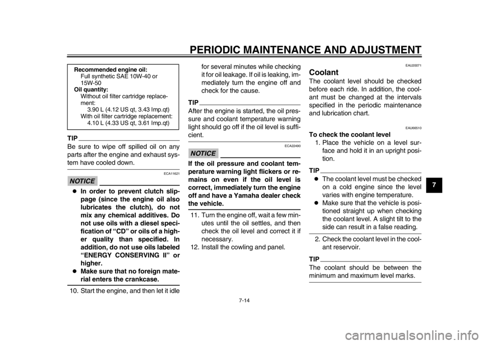
TIPBe sure to wipe off spilled oil on any
parts after the engine and exhaust sys-tem have cooled down.NOTICE
ECA11621
In order to prevent clutch slip-
page (since the engine oil also
lubricates the clutch), do not
mix any chemical additives. Do
not use oils with a diesel speci-
fication of “CD” or oils of a high-
er quality than specified. In
addition, do not use oils labeled
“ENERGY CONSERVING II” or
higher.
Make sure that no foreign mate-rial enters the crankcase.
10. Start the engine, and then let it idle for several minutes while checking
it for oil leakage. If oil is leaking, im-
mediately turn the engine off and
check for the cause.
TIPAfter the engine is started, the oil pres-
sure and coolant temperature warning
light should go off if the oil level is suffi-cient.NOTICE
ECA22490
If the oil pressure and coolant tem-
perature warning light flickers or re-
mains on even if the oil level is
correct, immediately turn the engine
off and have a Yamaha dealer checkthe vehicle.
11. Turn the engine off, wait a few min- utes until the oil settles, and then
check the oil level and correct it if
necessary.
12. Install the cowling and panel.
EAU20071
CoolantThe coolant level should be checked
before each ride. In addition, the cool-
ant must be changed at the intervals
specified in the periodic maintenance
and lubrication chart.
EAU66510
To check the coolant level 1. Place the vehicle on a level sur- face and hold it in an upright posi-
tion.TIP
The coolant level must be checked
on a cold engine since the level
varies with engine temperature.
Make sure that the vehicle is posi-
tioned straight up when checking
the coolant level. A slight tilt to theside can result in a false reading.
2. Check the coolant level in the cool- ant reservoir.
TIPThe coolant should be between theminimum and maximum level marks.
Recommended engine oil:Full synthetic SAE 10W-40 or
15W-50
Oil quantity:
Without oil filter cartridge replace-
ment: 3.90 L (4.12 US qt, 3.43 Imp.qt)
With oil filter cartridge replacement: 4.10 L (4.33 US qt, 3.61 Imp.qt)
2CR-9-E0_1.book 14 ページ 2015年1月5日 月曜日 午前11時54分