ESP Abarth 500 2018 Owner handbook (in English)
[x] Cancel search | Manufacturer: ABARTH, Model Year: 2018, Model line: 500, Model: Abarth 500 2018Pages: 192, PDF Size: 5.86 MB
Page 70 of 192
Group Weight range
Group 1 9-18 kg
Group 2 15 - 25 kg
Group 3 22 - 36 kg
All restraint devices must bear the
type-approval data, together with the
control mark, on a label solidly fixed to
the child restraint system which must
never be removed.
Lineaccessori Abarth offers child
restraint systems for each weight
group. These devices are
recommended having been specifically
designed for Abarth cars.
FITTING A CHILD
RESTRAINT SYSTEM
WITH SEAT BELTS
82) 83) 84) 85)
The Universal child restraint systems
installed with the seat belts only are
type-approved on the basis of the ECE
R44 standard and are divided into
various weight groups.
WARNING The figures are indicative
and provided for assembly purposes
only. Fit the child restraint system
according to the instructions, which
must be included.IMPORTANT NOTE After an accident of
a certain severity, it is recommended
that you replace both the child restraint
system and the seat belt to which it
was secured.
GROUP 0 and 0+
Babies up to 13 kg must be carried
with a rear facing child restraint system
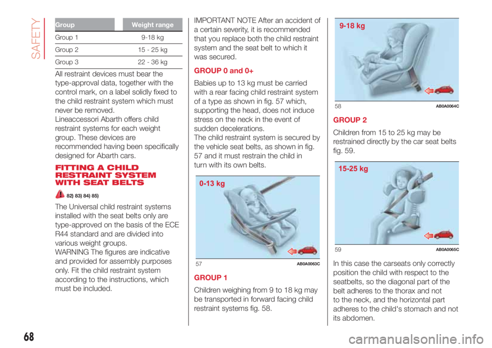
of a type as shown in fig. 57 which,
supporting the head, does not induce
stress on the neck in the event of
sudden decelerations.
The child restraint system is secured by
the vehicle seat belts, as shown in fig.
57 and it must restrain the child in
turn with its own belts.
GROUP 1
Children weighing from 9 to 18 kg may
be transported in forward facing child
restraint systems fig. 58.GROUP 2
Children from 15 to 25 kg may be
restrained directly by the car seat belts
fig. 59.
In this case the carseats only correctly
position the child with respect to the
seatbelts, so the diagonal part of the
belt adheres to the thorax and not
to the neck, and the horizontal part
adheres to the child's stomach and not
its abdomen.
57AB0A0063C
9-18 kg
58AB0A0064C
59AB0A0065C
68
SAFETY
Page 84 of 192
STARTING THE
ENGINE
The car is fitted with an electronic
engine lock device: if the engine fails to
start, see the paragraph "Fiat CODE
system" in the "Knowing your car"
chapter.
PROCEDURE
Proceed as follows:
engage the handbrake and place
the gearbox lever in neutral;
fully depress the clutch pedal
without touching the accelerator;
turn the ignition key to AVV and
release it as soon as the engine starts.
If the engine does not start at the
first attempt, return the ignition key to
STOP before repeating the starting
procedure.
If, with key at MAR, the
symbol on
the display stays on together with
the
warning light on the instrument
panel, it is advisable to turn the key to
STOP and then back to MAR. If the
warning light remains on, try with the
other keys provided with the car.
Contact an Abarth Dealership if you still
cannot start the engine.
15) 16)
108) 109)
WARMING UP THE
ENGINE JUST AFTER IT
HAS STARTED
Proceed as follows:
drive off slowly, letting the engine
turn at medium revs. Do not accelerate
abruptly;
do not demand full performance at
first. It is advisable to wait until the
engine coolant temperature indicator
starts moving.
17)
SWITCHING OFF THE
ENGINE
Turn the ignition key to STOP while the
engine is idling.
IMPORTANT After a taxing drive, you
should allow the engine to "catch
its breath" before turning it off by letting
it idle to allow the temperature in the
engine compartment to fall.
18)
WARNING
15)It is advisable not to demand maximum
performance from your car (e.g. excessive
acceleration, long distances at maximum
rpm, excessively intense braking, etc.)
when it is first used.
16)When the engine is switched off never
leave the key turned to MAR-ON to prevent
useless current absorption from draining
the battery.
17)Never, under any circumstances, jump
start the engine by pushing, towing or
coasting downhill. This could cause fuel to
flow into the catalytic converter and
damage it beyond repair.
18)A quick burst on the accelerator before
stopping the engine serves no practical
purpose; it wastes fuel and is especially
damaging to turbocharged engines.
WARNING
108)It is dangerous to run the engine in
enclosed areas. The engine takes in
oxygen and releases carbon dioxide,
carbon monoxide and other toxic gases.
109)Remember that the brake servo
and power steering are not operational until
the engine has been started, therefore
much effort than usual is required on the
brake pedal and steering wheel.
82
STARTING AND DRIVING
Page 87 of 192
STARTING THE CAR
NOTES
On starting, the system sets itself to
AUTO mode.
Using the 1, N, R buttons with the
brake pedal pressed, 1stgear, neutral
(N) or reverse (R) can be engaged.
Using the 1, N, R buttons without
pressing the brake pedal, the system
does not change gear.
The levers on the steering wheel will
not engage any gear, even with the
brake pedal pressed.
If the car is switched off with SPORT
or NORMAL modes active, the mode
previously set is kept when the engine
is restarted.
OPERATING MODE
The transmission can function in two
operating modes:
the first is manual (MANUAL). In this
mode the driver decides directly when
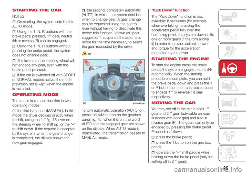
to shift, using the "+” fig. 76 lever on
the steering wheel to shift up, or the "–"
to shift down. If the request is accepted
by the system, when the gear change
is completed, the display shows the
new gear engaged.
the second, completely automatic
(AUTO), in which the system decides
when to change gear. A gear change
can be requested using the control
lever without having to deactivate this
mode: this function, known as “gear
suggestion”, suspends the automatic
mode for the time necessary to select
the gear requested by the driver.
20)
To turn automatic operation (AUTO) on,
press the A/M button on the gearbox
panel fig. 75; when it is on, the word
AUTO and the engaged gear are shown
on the display. When AUTO mode is
deactivated, the transmission passes to
MANUAL mode.“Kick Down” function
The "Kick Down" function is also
available: if necessary (for example
when overtaking), pressing the
accelerator pedal fully over the
hardening point, the system downshifts
one or more gears (if the rpm allows
it) in order to provide suitable power
and torque for the acceleration
requested by the driver.
STARTING THE ENGINE
To start the engine press the brake
pedal: the system engages neutral (N)
automatically. When the starting
procedure is complete, you can hold
the brake pedal down and press the 1
or R buttons on the transmission panel
to engage 1
stor reverse (R) gear
respectively.
MOVING THE CAR
You may set off in the car in both 1
st
gear and 2ndgear (advisable on road
surfaces with poor grip) and also in
reverse gear (R). The gears can only be
engaged by pressing the brake pedal.
Proceed as follows:
press the brake pedal;
press the 1 button on the gearbox
panel;
operate the “+” shift paddle while
holding down the brake pedal (only for
setting off in 2
ndgear);
76AB0A0335C
85
Page 89 of 192
When necessary, you can engage
1stgear, reverse (R) or neutral (N) with
the engine off, the key at AVV and
the brake pressed. In this case, it is
advisable to change allowing at least 5
seconds to elapse between one gear
change and the next to safeguard
the operation of the hydraulic system
and the pump in particular.
Fully and quickly depressing the
accelerator pedal activates a function
that allows a "lively" departure.
For starting uphill, accelerating
gradually but fully immediately after
having released the handbrake or the
brake pedal allows the engine to greatly
increase the rpm and tackle the
steepest gradients with more torque to
the wheels.
WARNING
20)Using the levers incorrectly (levers
pushed towards the dashboard) could
break them.
SPORT FUNCTION
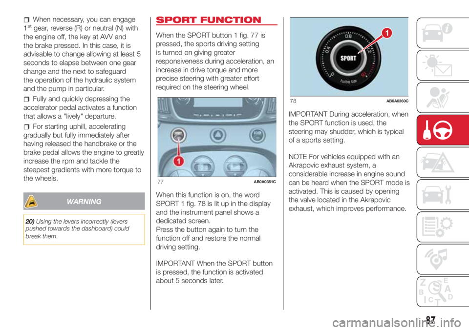
When the SPORT button 1 fig. 77 is
pressed, the sports driving setting
is turned on giving greater
responsiveness during acceleration, an
increase in drive torque and more
precise steering with greater effort
required on the steering wheel.
When this function is on, the word
SPORT 1 fig. 78 is lit up in the display
and the instrument panel shows a
dedicated screen.
Press the button again to turn the
function off and restore the normal
driving setting.
IMPORTANT When the SPORT button
is pressed, the function is activated
about 5 seconds later.IMPORTANT During acceleration, when
the SPORT function is used, the
steering may shudder, which is typical
of a sports setting.
NOTE For vehicles equipped with an
Akrapovic exhaust system, a
considerable increase in engine sound
can be heard when the SPORT mode is
activated. This is caused by opening
the valve located in the Akrapovic
exhaust, which improves performance.
77AB0A0351C
1
78AB0A0360C
87
Page 90 of 192

PARKING SENSORS
(where provided)
Parking sensors are located in the rear
bumper to detect and inform the driver,
through an acoustic and visual warning,
of the presence of obstacles at the
rear part of the car. The sound may be
intermittent or continuous depending
on the distance from the obstacle.
ACTIVATION
The sensors are automatically activated
when reverse gear is engaged. As the
obstacle behind the vehicle gets closer
to the car, the acoustic signal becomes
more frequent.
ACOUSTIC SIGNAL
When reverse gear is engaged and
there is an obstacle behind the car, an
acoustic warning is activated. The
frequency of the acoustic warning
increases as the distance between the
obstacle and the bumper decreases,
becoming continuous when the
distance is less than 30 cm.
Detection distances
If several obstacles are detected by the
sensors, only the nearest one is
considered.When parking, take the utmost care
over obstacles that may be above
or under the sensor.
Objects close to the car are not
detected under certain circumstances
and could therefore cause damage
to the car or be damaged.
113)
21) 22)
INDICATIONS ON
DISPLAY
When the sensors are activated, the
screen shown in fig. 79 appears on the
display.In addition to the acoustic warning,
information about the presence and
distance from the obstacle is given
visually on the instrument panel display.
The coloured arcs at the rear of the
car indicate that an obstacle has been
detected. The system indicates a
detected obstacle by displaying an arc
according to the distance of the
obstacle and its position in relation to
the car. If an objects is detected to the
rear of the car (to the side or at the
centre), the display shows an flashing
arc in the corresponding zone and
an intermittent sound is emitted. As the
car approaches the object, the display
shows one or more flashing arcs that
approach the car, and the sound
becomes more frequent until it
becomes continuous. The colour on the
display depends on the distance from
and position of the obstacle. As the
distance between the car and obstacle
decreases, the arcs change from yellow
to flashing red (to the right, at the
centre or to the left).
79AB0A0390C
88
STARTING AND DRIVING
Page 91 of 192

WARNING
21)For correct operation of the system,
sensors must always be clean from mud,
dirt, snow or ice. Be careful not to scratch
or damage the sensors while cleaning
them. Avoid using dry, rough or hard
cloths. The sensors must be washed using
clean water, with the addition of vehicle
shampoo if necessary. When using special
washing equipment such as high pressure
jets or steam cleaning, clean the sensors
very quickly keeping the jet more than
10 cm away.
22)Have interventions on the bumper in
the area of the sensors carried out only by
an Abarth Dealership. Interventions on
the bumper that are not carried out
properly may compromise the operation of
the parking sensors.
WARNING
113)Parking and other dangerous
manoeuvres are, however, always the
driver’s responsibility. While carrying out
these manoeuvres, always make sure that
no people (especially children) or animals
are in the area concerned. The parking
sensors are an aid for the driver, but the
driver must never allow their attention
to lapse during potentially dangerous
manoeuvres, even those executed at low
speeds.
REFUELLING THE
VEHICLE
Stop the engine before refuelling.
IMPORTANT Never introduce leaded
petrol to the tank, even in small
amounts in an emergency, as this
would damage the catalytic converter
beyond repair.
REFUELLING CAPACITY
To ensure that you fill the tank
completely, top up twice after the first
click of the fuel supply gun. Further
top-ups could cause faults in the fuel
supply system.
FUEL TANK CAP
Plug 2 fig. 80 is fitted with a cable that
secures it to flap 1 so that it cannot
be lost.Unscrew cap 2 using the ignition key.
The sealing may cause a slight pressure
increase in the tank. A little breathing
off, while slackening the cap is
absolutely normal. When refuelling,
fasten the plug to the device inside the
flap as shown in fig. 80.
114)
Fuels - identification of
vehicle compatibility.
Graphic symbol for
consumer information in
accordance with
EN16942
The symbols shown below facilitated
recognising the correct fuel type to
be used on your car.
Before proceeding with refuelling,
check the symbols inside the fuel filler
flap (where provided) and compare
them with the symbols shown on the
fuel pump (where provided).
Symbols for petrol powered cars
1
2
80AB0A0058C
89
Page 94 of 192

HAZARD WARNING
LIGHTS
These lights are turned on by pressing
the button 1 fig. 81, regardless of the
position of the ignition key.
With the device on, warning lights
andlight up in the instrument
panel.
Press the button 1 again to switch the
lights off.
IMPORTANT The use of hazard warning
lights is governed by the highway
code of the country you are driving in:
comply with legal requirements.
Emergency braking
In the event of an emergency braking,
the hazard warning lights switch on
automatically together with warning
lights
andon the instrument
panel.The lights switch off automatically when
emergency braking ceases.
CHANGING A BULB
GENERAL
INSTRUCTIONS
Before changing a bulb check the
contacts for oxidation;
burnt bulbs must be replaced by
others of the same type and power;
always check the headlight beam
direction after changing a bulb;
when a light is not working, check
that the corresponding fuse is intact
before replacing a bulb. For the location
of fuses, refer to the paragraph
"Replacing fuses" in this chapter.
115) 116)23) 24)
IMPORTANT When the weather is cold
or damp or after heavy rain or washing,
the surface of headlights or rear lights
may steam up and/or form drops of
condensation on the inside. This is
a natural phenomenon due to the
difference in temperature and humidity
between the inside and the outside
of the glass which does not indicate a
fault and does not compromise the
normal operation of lighting devices.
The mist disappears quickly when the
lights are turned on, starting from
the centre of the diffuser, extending
progressively towards the edges
81AB0A0350C
92
IN AN EMERGENCY
Page 97 of 192

WARNING
23)Halogen bulbs must be handled holding the metal part only. Touching the transparent part of the bulb with your fingers may reduce the
intensity of the emitted light and even reduce the lifespan of the bulb. In the event of accidental contact, wipe the bulb with a cloth moistened
with alcohol and let the bulb dry.
24)Where possible, it is advisable to have bulbs changed at an Abarth Dealership. The correct operation and direction of the exterior lights
are absolutely essential for the safety of the car and of compliance with the law.
95
Page 101 of 192

REPLACING FUSES
GENERAL INFORMATION
Fuses protect the electrical system:
they intervene (blow) in the event of a
failure or improper action on the
system.
118) 119) 120) 121) 122) 123)
To facilitate fuse replacement, use the
pliers hooked inside the fuse box lid on
the dashboard left-hand side.
Refer to the tables on the following
pages to identify the protective fuse.
FUSE LOCATION
Dashboard fuse box
To access the fuse you must remove
the press-fit cover 5 fig. 93.
The 5 A fuse for door mirror demisting
is located in the diagnosis socket
area, as shown in fig. 94.The fuse box shown in fig. 96 is located
in the lower area next to the pedal
unit.
Engine compartment
junction box
The fuse box is located on the right
side of the engine compartment, next
to the battery. To access the fuses,
proceed as follows:
Fully tighten the screw 1 fig. 95;
at the same time slowly rotate the
screw anticlockwise, until resistance is
encountered (do not overtighten);
slowly release the screw;
opening is indicated by the entire
screw head coming out of its housing;
remove cover 2, sliding it upwards
on the side guides, as indicated in
the figure;
after replacing the fuse, refit the
cover, making sure that it is closed
properly.
The number identifying the electrical
component corresponding to each fuse
is shown on the cover fig. 97.
25)
93AB0A0291C
94AB0A0317C
12
95AB0A0375C
99
Page 117 of 192
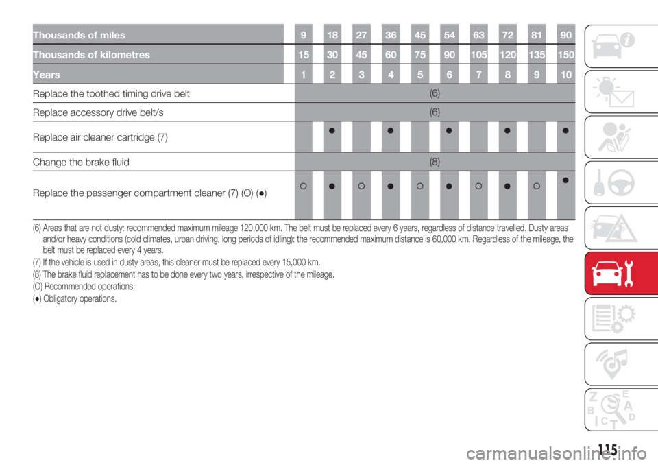
Thousands of miles 9 18 27 36 45 54 63 72 81 90
Thousands of kilometres 15 30 45 60 75 90 105 120 135 150
Years 1 2 3 4 5 6 7 8 9 10
Replace the toothed timing drive belt(6)
Replace accessory drive belt/s(6)
Replace air cleaner cartridge (7)
Change the brake fluid(8)
Replace the passenger compartment cleaner (7) (O) (●)
(6) Areas that are not dusty: recommended maximum mileage 120,000 km. The belt must be replaced every 6 years, regardless of distance travelled. Dustyareas
and/or heavy conditions (cold climates, urban driving, long periods of idling): the recommended maximum distance is 60,000 km. Regardless of the mileage, the
belt must be replaced every 4 years.
(7) If the vehicle is used in dusty areas, this cleaner must be replaced every 15,000 km.
(8) The brake fluid replacement has to be done every two years, irrespective of the mileage.
(O) Recommended operations.
(●) Obligatory operations.
115