buttons Abarth Grande Punto 2007 Owner handbook (in English)
[x] Cancel search | Manufacturer: ABARTH, Model Year: 2007, Model line: Grande Punto, Model: Abarth Grande Punto 2007Pages: 207, PDF Size: 3.01 MB
Page 18 of 207
16
SAFETY
DEVICES
CORRECT USE
OF THE CAR
WARNING
LIGHTS AND
MESSAGES
IN AN
EMERGENCY
CAR
MAINTENANCE
TECHNICAL
SPECIFICATIONS
INDEX
DASHBOARD
AND CONTROLS
fig. 18F0R0019m
fig. 16F0M2006gfig. 17F0M050Ab
RECONFIGURABLE
MULTIFUNCTION
DISPLAY
The car may be equipped with reconfig-
urable a multifunctional display that, ac-
cording to the settings made, will show
useful driving information.
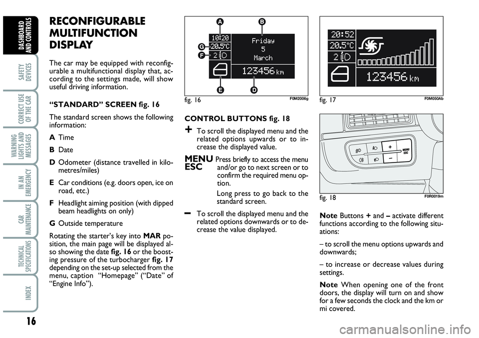
“STANDARD” SCREEN fig. 16
The standard screen shows the following
information:
ATime
BDate
DOdometer (distance travelled in kilo-
metres/miles)
ECar conditions (e.g. doors open, ice on
road, etc.)
FHeadlight aiming position (with dipped
beam headlights on only)
GOutside temperature
Rotating the starter’s key into MARpo-
sition, the main page will be displayed al-
so showing the date fig. 16or the boost-
ing pressure of the turbocharger fig. 17
depending on the set-up selected from the
menu, caption “Homepage” (“Date” of
“Engine Info”).CONTROL BUTTONS fig. 18
+To scroll the displayed menu and the
related options upwards or to in-
crease the displayed value.
MENU Press briefly to access the menuESCand/or go to next screen or to
confirm the required menu op-
tion.
Long press to go back to the
standard screen.
–To scroll the displayed menu and the
related options downwards or to de-
crease the value displayed. NoteButtons +and –activate different
functions according to the following situ-
ations:
– to scroll the menu options upwards and
downwards;
– to increase or decrease values during
settings.
NoteWhen opening one of the front
doors, the display will turn on and show
for a few seconds the clock and the km or
mi covered.
Page 19 of 207
17
SAFETY
DEVICES
CORRECT USE
OF THE CAR
WARNING
LIGHTS AND
MESSAGES
IN AN
EMERGENCY
CAR
MAINTENANCE
TECHNICAL
SPECIFICATIONS
INDEX
DASHBOARD
AND CONTROLS
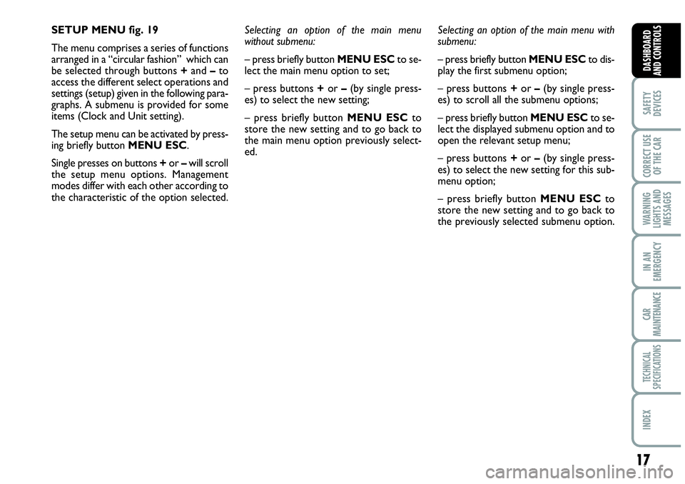
SETUP MENU fig. 19
The menu comprises a series of functions
arranged in a “circular fashion” which can
be selected through buttons +and –to
access the different select operations and
settings (setup) given in the following para-
graphs. A submenu is provided for some
items (Clock and Unit setting).
The setup menu can be activated by press-
ing briefly button MENU ESC.
Single presses on buttons +or –will scroll
the setup menu options. Management
modes differ with each other according to
the characteristic of the option selected.Selecting an option of the main menu
without submenu:
– press briefly button MENU ESCto se-
lect the main menu option to set;
– press buttons +or –(by single press-
es) to select the new setting;
– press briefly button MENU ESCto
store the new setting and to go back to
the main menu option previously select-
ed.Selecting an option of the main menu with
submenu:
– press briefly button MENU ESCto dis-
play the first submenu option;
– press buttons +or –(by single press-
es) to scroll all the submenu options;
– press briefly button MENU ESCto se-
lect the displayed submenu option and to
open the relevant setup menu;
– press buttons +or –(by single press-
es) to select the new setting for this sub-
menu option;
– press briefly button MENU ESC to
store the new setting and to go back to
the previously selected submenu option.
Page 21 of 207
19
SAFETY
DEVICES
CORRECT USE
OF THE CAR
WARNING
LIGHTS AND
MESSAGES
IN AN
EMERGENCY
CAR
MAINTENANCE
TECHNICAL
SPECIFICATIONS
INDEX
DASHBOARD
AND CONTROLS
NoteThe speed may be set in the range
from 30 to 200 km/h, or from 20 to 125
mph according to the previously chosen
unit (see “Setting the distance unit”) de-
scribed below. The setting will in-
crease/decrease by five units each time
button +/–is pressed. Hold button +/–
pressed to increase/decrease the setting
rapidly. Complete the setting by briefly
pressing the button when you approach
the required setting.
– briefly press button MENU ESCto go
back to the menu screen or press the but-
ton for long to go back to the standard
screen without storing settings.To cancel the setting, proceed as follows:
– briefly press button MENU ESC: (On)
will blink on the display;
– press button –: (Off) will flash on the dis-
play;
– briefly press button MENU ESCto go
back to the menu screen or press the but-
ton for long to go back to the standard
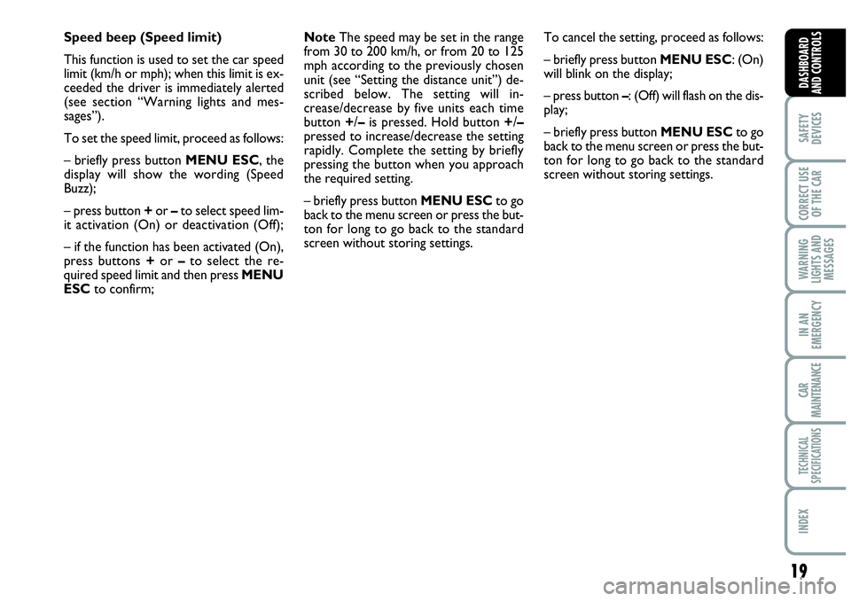
screen without storing settings. Speed beep (Speed limit)
This function is used to set the car speed
limit (km/h or mph); when this limit is ex-
ceeded the driver is immediately alerted
(see section “Warning lights and mes-
sages”).
To set the speed limit, proceed as follows:
– briefly press button MENU ESC, the
display will show the wording (Speed
Buzz);
– press button +or –to select speed lim-
it activation (On) or deactivation (Off);
– if the function has been activated (On),
press buttons +or –to select the re-
quired speed limit and then press MENU
ESCto confirm;
Page 25 of 207
23
SAFETY
DEVICES
CORRECT USE
OF THE CAR
WARNING
LIGHTS AND
MESSAGES
IN AN
EMERGENCY
CAR
MAINTENANCE
TECHNICAL
SPECIFICATIONS
INDEX
DASHBOARD
AND CONTROLS
Language (Selecting the language)
The messages may be displayed in the fol-
lowing languages: Italian, German,
English, Spanish, French, Portuguese,
Dutch.
To set the required language proceed as
follows:
– briefly press button MENU ESC: the
previously set “language” “ will flash on the
display;
– press button +or –for setting;
– briefly press button MENU ESCto go
back to the menu screen or press the but-
ton for long to go back to the standard
screen without storing settings.Buzzer volume (Adjusting the
failure/warning buzzer volume)
With this function the volume of the
buzzer accompanying any failure/warning
indication can be adjusted according to 8
levels.
To adjust the volume proceed as follows:
– briefly press button MENU ESC: the
previously set volume “level” will flash on
the display;
– press button +or –for setting;
– briefly press button MENU ESCto go
back to the menu screen or press the but-
ton for long to go back to the standard
screen without storing settings.Button volume
(Button volume adjustment)
This function may be used to adjust the
volume of the beep accompanying the ac-
tivation of buttons MENU ESC, +and
–can be adjusted according to 8 levels.
To adjust the volume proceed as follows:
– briefly press button MENU ESC: the
previously set volume “level” will flash on
the display;
– press button +or –for setting;
– briefly press button MENU ESCto go
back to the menu screen or press the but-
ton for long to go back to the standard
screen without storing settings.
Belt buzzer (Buzzer activation
for S.B.R. indication)
This function can be only displayed after
Abarth Dealership has deactivated the
S.B.R. system (see paragraph “S.B.R. sys-
tem” in section “Safety devices”).
Page 26 of 207
24
SAFETY
DEVICES
CORRECT USE
OF THE CAR
WARNING
LIGHTS AND
MESSAGES
IN AN
EMERGENCY
CAR
MAINTENANCE
TECHNICAL
SPECIFICATIONS
INDEX
DASHBOARD
AND CONTROLS
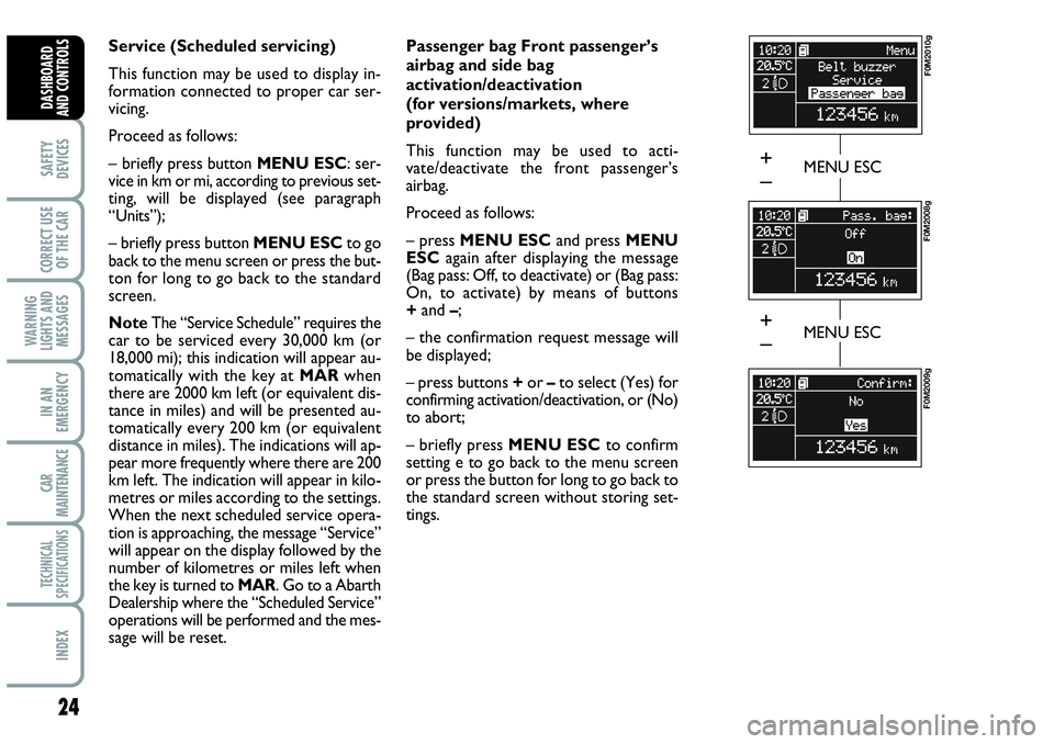
Service (Scheduled servicing)
This function may be used to display in-
formation connected to proper car ser-
vicing.
Proceed as follows:
– briefly press button MENU ESC: ser-
vice in km or mi, according to previous set-
ting, will be displayed (see paragraph
“Units”);
– briefly press button MENU ESCto go
back to the menu screen or press the but-
ton for long to go back to the standard
screen.
NoteThe “Service Schedule” requires the
car to be serviced every 30,000 km (or
18,000 mi); this indication will appear au-
tomatically with the key at MARwhen
there are 2000 km left (or equivalent dis-
tance in miles) and will be presented au-
tomatically every 200 km (or equivalent
distance in miles). The indications will ap-
pear more frequently where there are 200
km left. The indication will appear in kilo-
metres or miles according to the settings.
When the next scheduled service opera-
tion is approaching, the message “Service”
will appear on the display followed by the
number of kilometres or miles left when
the key is turned to MAR. Go to a Abarth
Dealership where the “Scheduled Service”
operations will be performed and the mes-
sage will be reset. Passenger bag Front passenger’s
airbag and side bag
activation/deactivation
(for versions/markets, where
provided)
This function may be used to acti-
vate/deactivate the front passenger’s
airbag.
Proceed as follows:
– press MENU ESCand press MENU
ESCagain after displaying the message
(Bag pass: Off, to deactivate) or (Bag pass:
On, to activate) by means of buttons
+and –;
– the confirmation request message will
be displayed;
– press buttons +or –to select (Yes) for
confirming activation/deactivation, or (No)
to abort;
– briefly press MENU ESCto confirm
setting e to go back to the menu screen
or press the button for long to go back to
the standard screen without storing set-
tings.
MENU ESC
F0M2010g
F0M2008g
F0M2009g
MENU ESC
+
–
+
–
Page 32 of 207
30
SAFETY
DEVICES
CORRECT USE
OF THE CAR
WARNING
LIGHTS AND
MESSAGES
IN AN
EMERGENCY
CAR
MAINTENANCE
TECHNICAL
SPECIFICATIONS
INDEX
DASHBOARD
AND CONTROLS
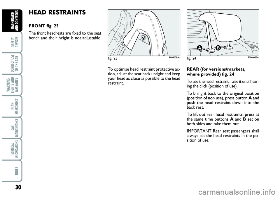
HEAD RESTRAINTS
FRONT fig. 23
The front headrests are fixed to the seat
bench and their height is not adjustable.
fig. 23F0M009Abfig. 24F0M0026m
To optimise head restraint protective ac-
tion, adjust the seat back upright and keep
your head as close as possible to the head
restraint. REAR (for versions/markets,
where provided) fig. 24
To use the head restraint, raise it until hear-
ing the click (position of use).
To bring it back to the original position
(position of non use), press button Aand
push the head restraint down into the
back rest.
To lift out rear head restraints: press at
the same time buttons Aand Bset on
both sides and take them out.
IMPORTANT Rear seat passengers shall
always set the head restraints in the po-
sition of use.
Page 43 of 207
41
SAFETY
DEVICES
CORRECT USE
OF THE CAR
WARNING
LIGHTS AND
MESSAGES
IIN AN
EMERGENCY
CAR
MAINTENANCE
TECHNICAL
SPECIFICATIONS
INDEX
DASHBOARD
AND CONTROLS
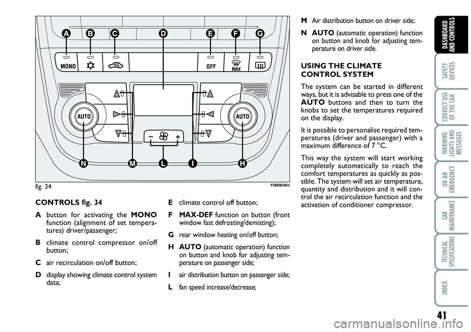
CONTROLS fig. 34
Abutton for activating the MONO
function (alignment of set tempera-
tures) driver/passenger;
Bclimate control compressor on/off
button;
Cair recirculation on/off button;
Ddisplay showing climate control system
data;
MAir distribution button on driver side;
N AUTO(automatic operation) function
on button and knob for adjusting tem-
perature on driver side.
USING THE CLIMATE
CONTROL SYSTEM
The system can be started in different
ways, but it is advisable to press one of the
AUTObuttons and then to turn the
knobs to set the temperatures required
on the display.
It is possible to personalise required tem-
peratures (driver and passenger) with a
maximum difference of 7 °C.
This way the system will start working
completely automatically to reach the
comfort temperatures as quickly as pos-
sible. The system will set air temperature,
quantity and distribution and it will con-
trol the air recirculation function and the
activation of conditioner compressor. Eclimate control off button;
F
MAX-DEFfunction on button (front
window fast defrosting/demisting);
Grear window heating on/off button;
H AUTO(automatic operation) function
on button and knob for adjusting tem-
perature on passenger side;
Iair distribution button on passenger side;
Lfan speed increase/decrease;
fig. 34F0M0039m
Page 44 of 207
42
SAFETY
DEVICES
CORRECT USE
OF THE CAR
WARNING
LIGHTS AND
MESSAGES
IN AN
EMERGENCY
CAR
MAINTENANCE
TECHNICAL
SPECIFICATIONS
INDEX
DASHBOARD
AND CONTROLS
During fully automatic operation, the on-
ly manual settings required are the fol-
lowing:
❒MONO, to align the air temperature
and distribution set on the passenger’s
side with that on the driver’s side;
❒•air recirculation, to keep it always
on or off;
❒-to speed up demisting/defrosting of
windscreen, side windows, rear window
and door mirrors;
❒
(to demist/defrost heated rear win-
dow and door mirrors.
During full automatic system operation,
you can change at any time set tempera-
tures, air distribution and fan speed by us-
ing the relevant buttons or knobs: the sys-
tem will automatically change its settings
to adjust to the new requirements.During (FULL AUTO) operation, chang-
ing air distribution and/or flow and/or
compressor activation and/or air recircu-
lation will make the FULLwording dis-
appear. In this way the system will keep
on controlling automatically all functions,
excluding those changed manually. Fan
speed is the same for every area of the
passenger compartment.
Air temperature adjusting
knobs H - N
Turning the knobs clockwise or counter-
clockwise, respectively highers or lowers
the temperature of the air required re-
spectively in the front left zone (knob N) or
in the right zone (knob H) of the passenger
compartment. Since the system controls
two zones of the passenger compartment,
it is possible to personalise required tem-
peratures (driver and passenger) with a
maximum difference of 7 °C. The temper-
atures set are shown on the displays near
the relevant knobs. Pressing button A
(MONO) automatically aligns the temper-
ature on the passenger’s side with that on
the driver’s side; you can therefore set the
same temperature for both zones by turn-
ing knob Non driver side. Separate oper-
ation of air temperatures and distribution is
restored by turning knobs Hor pressing
again button A(MONO) when the button
led is on.Turn the knobs fully clockwise or counter-
clockwise to engage respectively HI(max-
imum heating) or LO(maximum cooling).
To deactivate these two functions, just
turn the temperature knob and set the re-
quired temperature.
Front air distribution buttons I-M
Pressing these buttons it is possible to
choose manually one of the seven possi-
ble air distributions to the passenger com-
partment (right or left side):NAir flow to the windscreen and front
side window vents to demist or de-
frost them.
˙Air flow at central and side dashboard
vents to ventilate the chest and the
face during the hot season.
OAir flow towards the front and rear
lower parts of the passenger com-
partment. Due to the natural tenden-
cy of heat to spread upwards, this type
of distribution allows heating of the
passenger compartment in the short-
est time, also giving a prompt feeling
of warmth.
Page 45 of 207
43
SAFETY
DEVICES
CORRECT USE
OF THE CAR
WARNING
LIGHTS AND
MESSAGES
IIN AN
EMERGENCY
CAR
MAINTENANCE
TECHNICAL
SPECIFICATIONS
INDEX
DASHBOARD
AND CONTROLS
˙Splitting of the air flow
Obetween the vents to the lower part
of the passenger compartment
(warmest air) and the dashboard cen-
tre and side outlets (coolest air). This
air flow distribution is particularly use-
ful in spring and autumn when the sun
is shining.
NSplitting of the air flow between
Owindscreen and front side window
demisting/defrosting vents and the
lower part of the passenger compart-
ment. This type of air distribution al-
lows satisfactory heating of the pas-
senger compartment while preventing
possible misting of the windows.
NSplitting of the air flow between
˙windscreen demisting/defrosting vents
and central and side dashboard vents.
This type of air distribution allows sat-
isfactory ventilation when the sun is
shining.
NSplitting of the air flow between
˙all car vents.
O
During FULL AUTOoperation the sys-
tem will control automatically air distrib-
ution choosing the most appropriate ac-
cording to climate conditions. When in
FULL AUTOdistribution leds are off.The type of air distribution, when select-
ed by hand, is shown by lighting up of the
relevant led on the selected button. In the
combined function, pressing a button will
activate the relevant function whereas,
pressing a button relevant to an already
operating function will turn off this func-
tion and the relevant button led. To re-
store automatic air distribution control af-
ter a manual selection, press button AU-
TO.
When the driver selects air distribution to
the windscreen, also the air distribution
on passenger side will be distributed to the
windscreen. The passenger can however
select the required air distribution by
pressing the relevant buttons.
Fan speed adjusting buttons L
Press button pto increase or to decrease
the fan speed and therefore the amount
of air admitted into the passenger com-
partment, although keeping the required
temperature set.The fan speed is shown by the lit bars on
the display:
❒max fan speed = all bars lit;
❒min fan speed = one bar lit.
The fan can be cut off only if the climate
control compressor has been switched off
pressing button B.
IMPORTANT To restore automatic fan
speed control after a manual adjustment,
press button AUTO.
AUTO buttons
(automatic operation) H-N
Pressing the AUTObutton (on driver
and/or front passenger side) the system au-
tomatically adjusts the amount and distri-
bution of the air admitted to the passenger
compartment, cancelling all the previous
manual adjustments. This condition is in-
dicated by the message FULL AUTOon
the front system display. Manual operation
of at least one automatic function (air re-
circulation, air distribution, fan speed or cli-
mate control compressor off) will cause
FULLmessage going off the display. This
means that automatic control is not com-
plete (except temperature control which is
always automatic).
Page 46 of 207
44
SAFETY
DEVICES
CORRECT USE
OF THE CAR
WARNING
LIGHTS AND
MESSAGES
IN AN
EMERGENCY
CAR
MAINTENANCE
TECHNICAL
SPECIFICATIONS
INDEX
DASHBOARD
AND CONTROLS
IMPORTANT Should the system (after
manual settings) be no longer able to guar-
antee the required temperature set in the
passenger compartment, the set tempera-
ture value will start flashing to indicate this
condition, after one minute the AUTO
message will turn off.
To restore system automatic control at
any time, after one or more manual ad-
justments, press button AUTO.
MONO button (to align set
temperatures and air
distribution) A
Pressing button MONOautomatically
aligns the temperature on the passenger
side with that on the driver side, it is
therefore possible to set the same tem-
perature and air distribution between the
two zones by turning the knob on driver
side. This function is provided to simplify
temperature adjustment of the whole pas-
senger compartment when only the dri-
ver is onboard. Separate operation of set
temperature and air distribution is re-
stored by turning knob H(to set tem-
perature on front passenger side) or by
pressing again button MONOwhen the
button led is on.Air recirculation on/off button C
Air recirculation works according to the
following operating logics:
❒automatic switching on, by pressing one
of the AUTObuttons and indicated by
the turning on of the AUTOicon on the
display near the car outline;
❒forced switching on (inside air recircu-
lation always on), indicated by the turn-
ing off of the button led Cand symbol
íon the display;
❒forced switching off (air recirculation
always off with air inlet from the out-
side), indicated by the turning off of the
button led and symbol
êon the dis-
play. Forced recirculation on/off can be
selected through button C.
IMPORTANT The inside air recirculation
system makes it possible to reach the re-
quired heating or cooling conditions faster.
It is however inadvisable to use it on
rainy/cold days as it would considerably
increase the possibility of the windows
misting inside, especially if the climate con-
trol system is off.When outside temperature is cold, recir-
culation is forced to off (outside air inlet)
to prevent window misting up.
In automatic operation inside air recircu-
lation will be controlled automatically by
the system according to outside environ-
mental conditions.
When setting manual recirculation, word-
ings FULLand AUTOdisappear from
the display.
It is inadvisable to use air re-
circulation on rainy/cold
days as it would considerably increase
the possibility of windows misting up
inside.
WARNING