Lash ACURA INTEGRA 1994 Service User Guide
[x] Cancel search | Manufacturer: ACURA, Model Year: 1994, Model line: INTEGRA, Model: ACURA INTEGRA 1994Pages: 1413, PDF Size: 37.94 MB
Page 556 of 1413

Transmission
Installation {cont'd)
14.
15.
Install new set rings on the end of the intermediate
shaft and the driveshaft.
Install the intermediate shaft.
SET RINGBeplace.
16.
10 x 139 N.m14.O kgf.m, 29 lbf.ftl
Install exhaust pipe A. and connect the heated oxv-gen sensor {HO2S) connector.
SELF-LOCKING NUT10 x 1.25 mm54 N.m (5.5 kgl.m,40 rbt.trlReplace.
GASKETReplace.
SELF.LOCKING NUTSI x 1.25 mm22 N.m 12.2 kgl'n,16 lbt.trlRepl6ce.
SHAFT
14-166
DAMPER PINCH BOLT10 x 1.25 mm43 N.m 14.4 kgf.m,32 tbr.ftl
1 7. Install the right and left drivershafts (see section l6l.
NOTE: Turn the right and left steering knuckle fullyoutward, and slide the right driveshaft into the
differential until you feel its spring clip engages theside geaf. Slide the left driveshaft into the intermedi-
ate shaft until you teel the spring clip of the inter-mediate shaft engage the driveshaft.
18. Install right damper fork, then install the right andlett balljoints to each lower arm with the castle nuts
and new cotter Dins.
\
COTTERReplace.CASTLE NUT12 x 1.25 mm49-59 N.m{5.O-6.0 ksf.m, 36-43
SELF.LOCKING NUT12 x 1 .25 mm64 N.m (6.5 kgl.h, 47 lbt.ftlReplace.
rbt'ft1
19. Install the splash shield.
6 x 10 mm BOLT
cltPs, 5
Page 568 of 1413
Differential (81881 enginel
Speciaf Tools ........ ........15-2
Differential
lllustrated Index ......... . 15-3
Backlash Inspection .... 15-4
Final Driven Gear Replacement ...... 15-4
Bearing Replacement .................... 1 5-5
Oil Seal Removal ........ 15-5
Side Clearance Adiustment ........... 15-6
Oil Seal lnstallation ..... 15-8
Page 571 of 1413
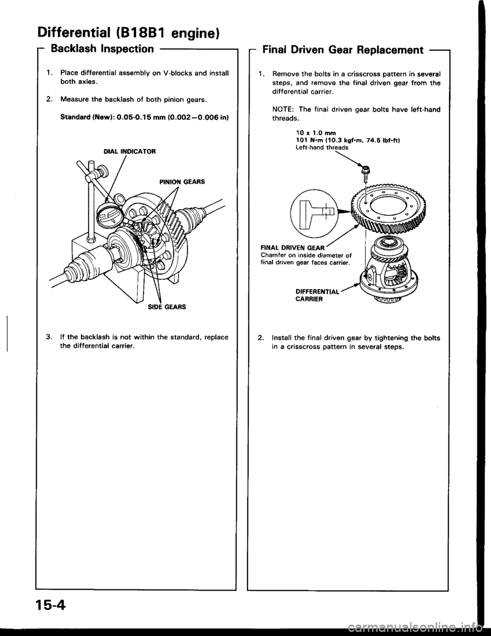
'1.Place difterential assembly on V-blocks and install
both axles.
M€asure the backlash of both pinion gears.
Standard (New):0.05-O.15 mm (0.OO2-0.006 inl
3. It the bscklssh is not within the standard, reDlace
the differential carrier.
DIAL II{OICATOR
Differential (818B1 enginel
Backlash InspectionFinal Driven Gear Replacement
1.Remove the bolts in a crisscross Datt€rn in several
steps, and remove the final driven gear from the
differential carrier.
NOTE: The final driven gear bolts have left-hand
threads.
10 x 1.0 mm101 N.m llO.3 kgl.m, 74.5 lbf.ftlLelt-hand threads
FINAL DRIVEIII GEARChamfer on inside diameter otlinal driven gear taces carrier.
DIFFEREI{TIALCARBIER
Install the final driven gear by tightening the bolts
in a c.isscross pattern in several steps.
15-4
Page 576 of 1413
Differential (818C1 enginel
Special Tools ........
Differential
lllustrated Index .........
Backlash Inspection
Final Driven Gear Replacement ......
Tapered Roller Bearing Replacement.
Oil Seal Removal
Bearing Outer Race Replacement ...
Tapered Roller Bearing Preload
Adjustment
Oil Seal Installation
1 5-10
15-1 1
15-12
15-12
15-13
15-13
15-14
15-15
15-17
Page 579 of 1413
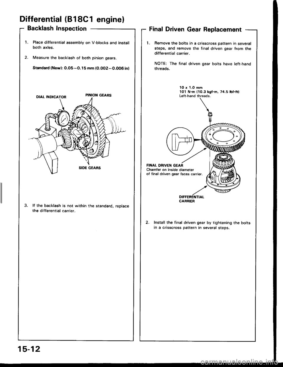
Differential (818C1 enginel
Backlash Inspection
Place ditterential assembly on V-btocks and instatlboth axles.
Measure the backlash of both pinion gears.
Standard (Now): 0.o5-o.15 mm {0.oo2-0.O06 in)
lf the backlash is not within the standard, reDlacethe differential carrier,
Final Driven Gear Replacement
1. Romove the bolts in a crisscross Dattern in several
steps, and remove the tinal driven gear f.om thedifferential carrier.
NOTE: The tinal driven gear bolts have lett-hand
threads.
10 x 1.O mm101 N.m (10.3 kgt.m, 74.5 lbf.ftlLeft-hand threads.
FII{AL DN|VEN GEARChamfer on inside diameterof linal driven g€ar taces carrier.
DIFFERETTTIALCABRIER
Install the final driven gear by tightening the bolts
in a crisscross pattern in several steps.
15-12
Page 588 of 1413
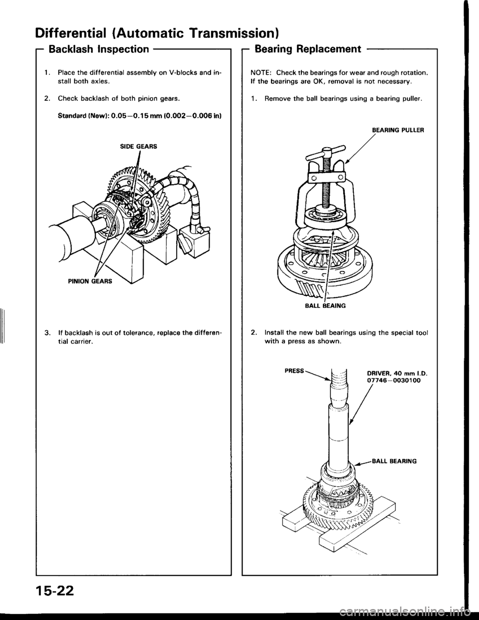
Differential (AutomaticTransmission)
Backlash InspectionBearing Replacement
1.Place the differential assembly on V-blocks and in-
stall both axles.
Check backlash of both pinion gears.
Standard (New): 0.05-O.15 mm (0.002-0.006 inl
3. lf backlash is out of tolerance, replace the differen-
tial carrier.
SIDE GEARS
NOTE: Check the bearings for wear and rough rotation.
lf the bearings are OK, removal is not necessary.
1. Remove the ball bearings using a bearing puller.
BEARING PULLER
Install the new ball bearings using the special tool
with a Dress as shown.
BALL BEAING
DRIVER, 40 mm l.D.07746 0030100
15-22
Page 1172 of 1413
Battery
a Battory tluid (6lectrolyt€l contains sulturic acid. lt may cauaa aevere burns iI it gots on your skin or in youl oyos.
Woar protoctivo clothing and I fac€ shield,- ll aloctrolyt6 gots on youl skin or clothos, rimo it off with wator immediately,- lf eloclrolyto g6ts in your oyos, tlush it out by splashing wat6r in youl eyes for at least 15 minutes; call a physiclan
immediately,
a A battery gives off hydrogon gas, lf ignit6d. tha hydrogsn will orploda and could crack tho baflory cas6 and splattor
acid on you. Koep spa*s. flames, and cigarottos away from the baftery.
a Overcharging will raiso ths tempelature ot th€ electrolyte. This may force electrolyte to splay out of the battery venta.
Follow lhe chargor manutacturer's instluctions and chargo tho battory at a prop61 rate.
NOTE: The original radio has a coded theft protection circuit. lt service to the car requires any of the lollowing, be sure
to get the customer's code number before- disconnecting the battery.- removing No. 32 (7.5 Al fuse from the under-hood fuse/relay box- removing the radio,
After service, reconnect power to the radio and turn it on. When the word "CODE" is displayed, enter the customer's
s-digir code to restore radio operation,
Use either a JCI or Bear ARBST tester, and follow the manufacturer's procedures. It you don'r have one of these com-puterized testers, follow this conventional test procedure:
To get accurate results, the temperature ot the electrolyte must be between TOoF l21ool and IOOoF {38oCl.
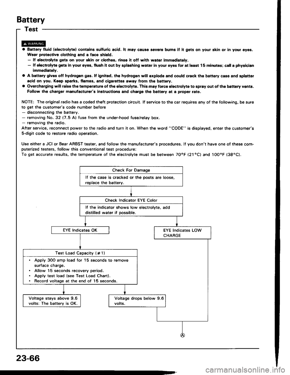
lf the case is cracked or the posts are loose,
replace the battery.
lf the indicator shows low electrolvte, add
distilled water it oossible.
Test Load Cspacity (# 1)
. Apply 3OO amp losd fo. 15 seconds to remove
surJace charge.. Allow 15 seconds recovery period.. Apply test load (see Test Load Chartl.. Record voltage at the end of 15 seconds.
Voltage stays above 9.6
volts: The batterv is OK.
23-66
Page 1250 of 1413
Integrated Control Unit
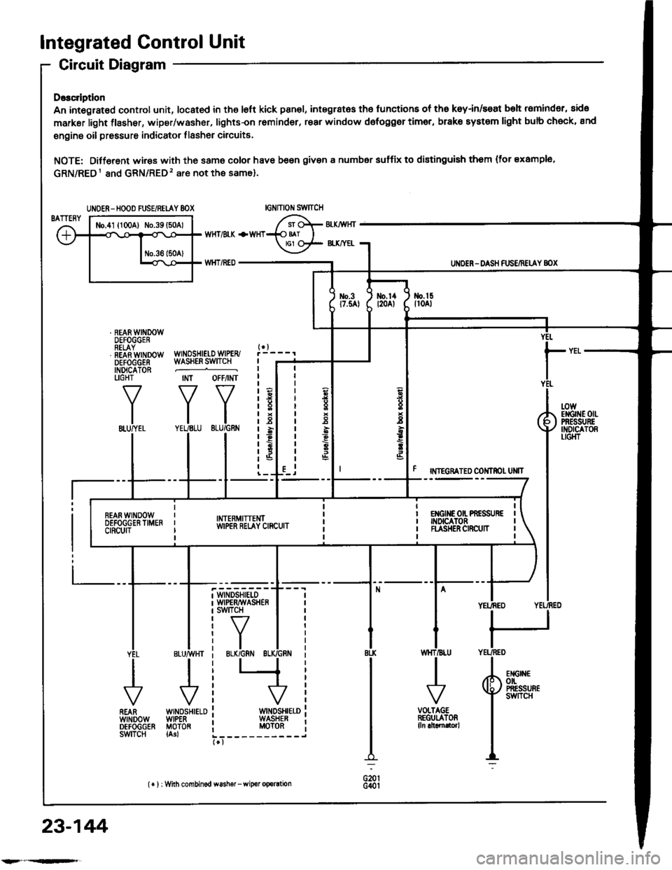
Circuit Diagram
D.3c ptlon
An integrat€d control unit, located in the left kick panel, integratss the functions of tho keyin/seat beh r6mind€r, sido
markar light {lasher, wiper/washer, lights-on r6minder, rear window dsfogger timer, brak€ system light bulb check, and
enging oil pressure indicator flasher circuitE,
NOTE: Difforent wires with the same color have be6n given a numbor suffix to distinguish them (for Example,
GRN/RED1 and GRN/RED'� are not the same).
WNOSHIELD WIPER/WASHER SWITCH
IMT OFFiINT
I
II
IIIIIIIIIIII
YEUEE
rl
t
P
UNOER - DASH FUS€/RETAY BOX
r NTEGRATED COI{TROI UNIT
t-0wErGrilE 0|lPRESSI'REINDICATORLIGI{T
WINDSHIELOWIPERAVASHERswtTcH
tr-/
IBLK/GRN BI
WINDSHIELOWIPERMOTOR{Asl
VOLTAGEREGULATOR{ln ahamator,
UNOER- HOOD FUSE/RELAY 8OX
I
r3
r8relit;rBt5I
23-144
lr ) : With combinod washef-wip€r oporation
Page 1254 of 1413
Integrated Control Unit
Input Test (cont'd)
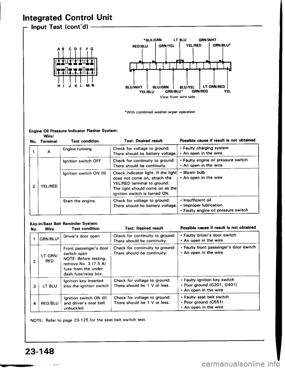
Engine Oil Pressure Indicator Flashal System:
Wire/
rWith combined washeFwipot operation
Test: Desired resultPossiblo c€use if r6rult is not obtainodNo. TelminalTsst condition
M
1Engine runningCheck for voltage to ground:
There should be battery voltage
. Faulty charging system. An oDen in the wire
YEL/RED
lgnition switch oFFCheck for continuity to gtound:
There should be continuitv.
. Faulty engine oil ptessure switch
. An oDen in the wire
lgnition switch ON (ll)Check indicator light. lf the light
does not come on, Sttach the
YEL/RED terminal to ground:
The light should come on as the
ignition switch is turned ON.
. Blown bulb. An open in the ware
Start the engine.Check for voltage to ground:
There should be battery voltage
Insufficient oil
lmproper lubrication
Faulty engine oil pressure switch
Key-in/Seat Bolt Reminder Systam:
No. WilaTest condition
NOTE: Refer to page 23-125 for the seat belt switch test.
Test: Dosired lesuhPossible causo if resuh is not obtainod
23-148'
GRN/BLU'Driver's door openCheck for continuity to ground;
There should be continuitv.
. Faulty driver's door switch
. An ooen in the wire
LT GRN/
RED
Front passenger's door
switch open
NOTE: Betore testing,
remove No. 3 (7.5 A)
tuse from the under-
dash fuse/relay box.
Check tor continuity to ground:
There should be continuitv.
. Faulty lront passenger's door switch
. An ooen in the wire
LT BLU
lgnition key inserted
into the ignition switch
Check for voltage to ground:
There should be 1 V or less.
Faulty ignition key switch
Poor ground (G201 , G401)
An ooen in the wite
RED/BLU
lgnition switch ON (ll)
and driver's seat belt
unbuckled
Check lor voltage to ground:
There should be 1 V or less.
Faulty seat belt switch
Poor ground {G551)
An open in the wire
;.rqFft,
Page 1255 of 1413
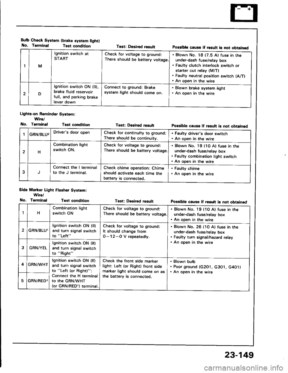
Bulb Check System
No. Tsrminal
(blake system lightl
Test condition
Lights-on Romind6r Systom:
Wire/
No, ToiminalT6Et condition
Side Markol Light Flashar System:
Wiro/
No. TerminalTest condition
Tost: Desirod resuhPossibls caus6 it result is not obtainod
Tost: Dositod rosuhPossibl6 caus6 if rosuh is not obtainod
Tast: Desired rosultPo$ible cause if result is not obtained
IM
lgnition switch at
STARTCheck lor voltage to ground:
There should be battery voltage.
Blown No. 18 {7.5 Al fuse in theunder-dash fuse/relay box
Faulty clutch int€rlock switch or
starter cut relay {M/T}Faulty neutral position switch (A/T)
An open in the wire
D
lgnition switch ON (ll),
brake fluid reservoir
tull, and parking brake
lever down
Connect to ground: Brake
system light should come on.
. Blown brake system light. An oDen in the wire
GRN/8LU'Driver's door openCheck for continuity to ground:
There should be continuity.
. Faulty driver's door switch. An oDen in the wire
H
Combination light
switch ON.
Check for voltage to g.ound:
There should be battery voltage
Blown No. l9 (1O A) tuse in the
under-dash fuse/relav box
Faulty combination light switch
An oDen in the wire
5
Connect the I terminal
to the J terminal.
Check chime operation: Chime
should activate each time the
batterv is connected,
. Faulty chime. An open in the wire
1H
Combination light
switch ON
Check for voltage to ground:
There should be battery voltage
. Blown No. 19 (1O A) tuse in the
under-dash fuse/relay box. An open in the wire
GRN/BLU1
lgnition switch ON {ll)and turn signal switch
to "Left"
Check for voltage to ground:
It should change from
O-12-O V repeatedly.
Blown No. 26 (10 A) luse in theunder-dash fuse/relav box
Faulty turn signal/hazard relay
An oDen in the wire2GRN/YEL
lgnition switch ON {ll)and turn signal switch
to "Right"
4GRN/WHTlgnition switch ON (ll)
and turn signal switch
to "Left (or Rightl":
Connect the H terminal
to the GRNMHT(or GRN/REDl) terminal.
Check the front side marker
light: Left (or Right) front sidemarker light should come on asthe batterv is connected.
Blown bulb
Poor ground (G2O1, c3O1, G4O1lAn open in the wire
GRN/REDl
23-149