horn ACURA INTEGRA 1994 Service User Guide
[x] Cancel search | Manufacturer: ACURA, Model Year: 1994, Model line: INTEGRA, Model: ACURA INTEGRA 1994Pages: 1413, PDF Size: 37.94 MB
Page 1307 of 1413
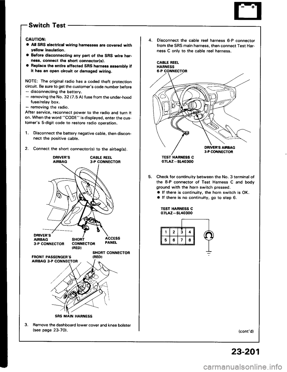
Switch Test
CAUTION:
a All SRS el6ctrical wiring harnossos are covarod withyellow inaulation.
a Beforo disconnecting any pan ot the SRS wire har-neaa, connoct ths short connector(s).a Roplace the entil€ afloctod SRS harne$ a$6mbly ifit has an open circuit or dsmagad wlring.
NOTE; The original radio has a coded theft protection
circuit. Be sure to get the customer's code number before- disconnecting the battery.- removing the No. 32 {7.5 A) fuse lrom the under-hoodtuse/relav box.- removing the radio.
After service, reconnect power to the radio and turn iton. When the word "CODE" is displayed, enter the cus-tomer's 5-digit code to restore radio operation.
1. Disconnect the battery negative cable, then discon-nect the positive cable.
2. Connect the short connector(sl to the airbag(sl.
DRIVER'SAIRBAGCABLE REEL3.P CO NECTOR
DRIVER'SAIRBAG3-PCO'TNECTOR COI{NECTOR{RED}
ACCESSPAI{EL
SHORT CONTIECTOR{REO}
Remove the dashboatd lower cover and kne€(see page 23-701.
5.
4. Disconnect the cable reel harness 6-P connector
from the SRS main harness, then connect Test Har-
ness C onlv to the cable reel harness.
CABLE REELHARNESS
TEST HAR ESS CoTLAz - SL/l{,3OO
Check for continuity between the No, 3 terminal ot
the 8-P connector of Test Harness C and body
ground with the horn switch pressed.
a lf there is continuity, the horn switch is OK.a lf there is no continuity, go to step 6.
TEST HARNESS COTLAZ-SI/I()3OO
(cont'd)
bolster
23-201
Page 1308 of 1413
Horn
SwitchTest(cont'd)
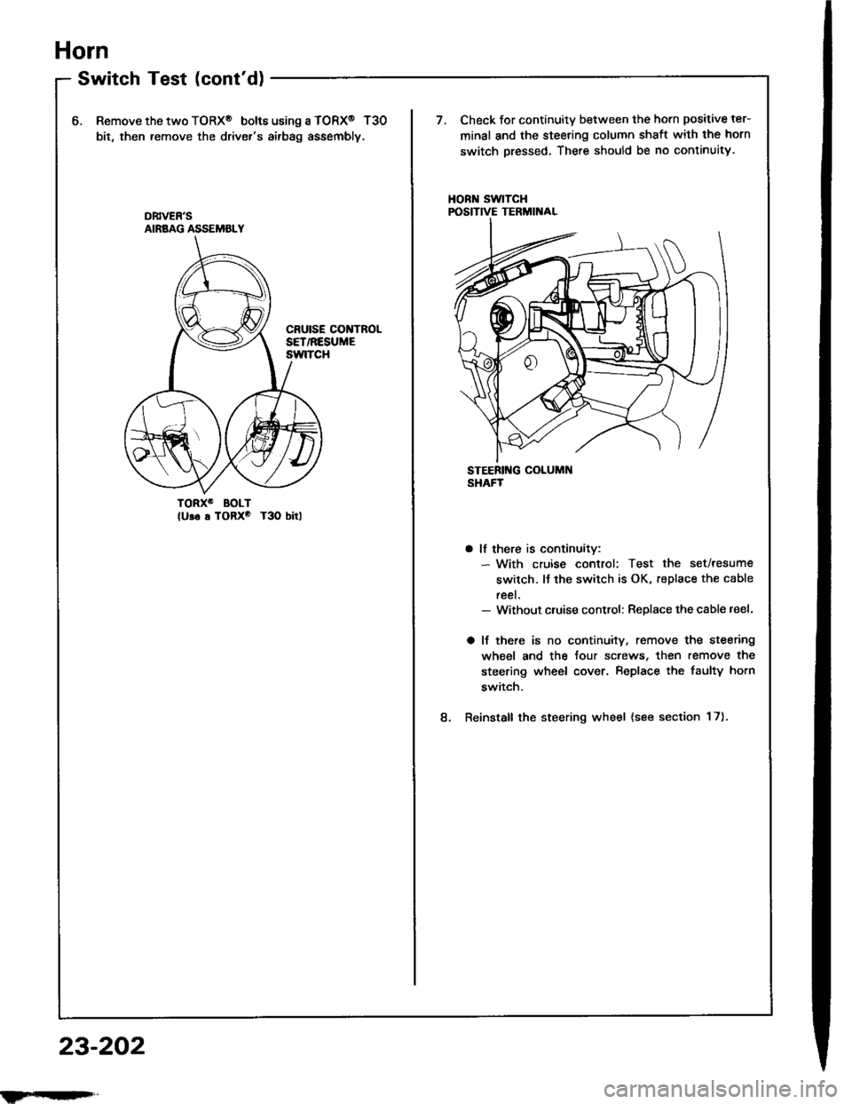
6.Remove the two TORX@ bolt6 using a TORX@ T30
bit, then remove the driver's airbag assembly.
Check for continuity between the horn positive ter-
minal and the steering column shaft with the horn
switch pressed, There should be no continuity.
HORN SwlTCHPOSITIVE TERMIITAL
TORXO BOLT(U!6 s TORxo T3O bitl
8.
a lf there is continuitv:- With cruise control: Test the set/resume
switch. lJ the switch is OK, replace the cable
reel.- Without cluise control: Replace the cable reel.
a lJ there is no continuity. remove the steering
wheel and the four screws, then remove the
steering wheel cover. Replace the faulty horn
switch.
Reinstall the steering wheel {see section 17).
DB|vEN'SAIRBAG ASSEMBLY
23-202
ilFrrI|qFrl"
Page 1309 of 1413
MOUNTI G AOLT
t.
2.
5.
Horn Test
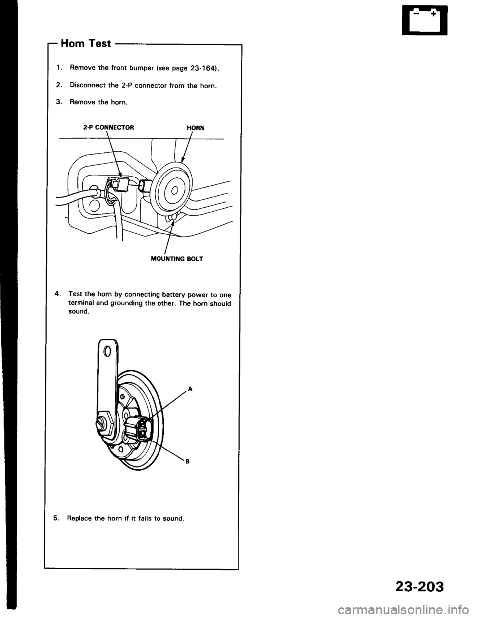
Remove the front bumper (see page 23-164).
Disconn€ct the 2-P connector from the hofn.
Remove the horn.
2-P COt{t{ECTOB
4. Test the horn by connecting battery power to oneterminsl and grounding the other, The horn shouldsound.
5. Reolace the horn if it fails to sound.
23-203
Page 1350 of 1413
+ No.24 ll5Al: 81881 onoineNo.24 l20Al: 818C1 ensine
UNDER-DASH FUSE/RELAY BOX
HORN
Y
UNOER _HOOD FUSE/RELAY BOX
No.4l (100A) No.39l50A)
INDICATORTIGHT{0,91W}
IP
I D Suur
6yffi Bi,G#,,'.
BTK
t-
G201G401
II
I
f7
VEHICLE SPEEDSENSOR iVSS)
M/r : CLUTCH SWITCH IA/T : A/T GEAR IPOS|T|oN SWTTCH IInIEI,E) I
PNK
BI-K
T
G201G401
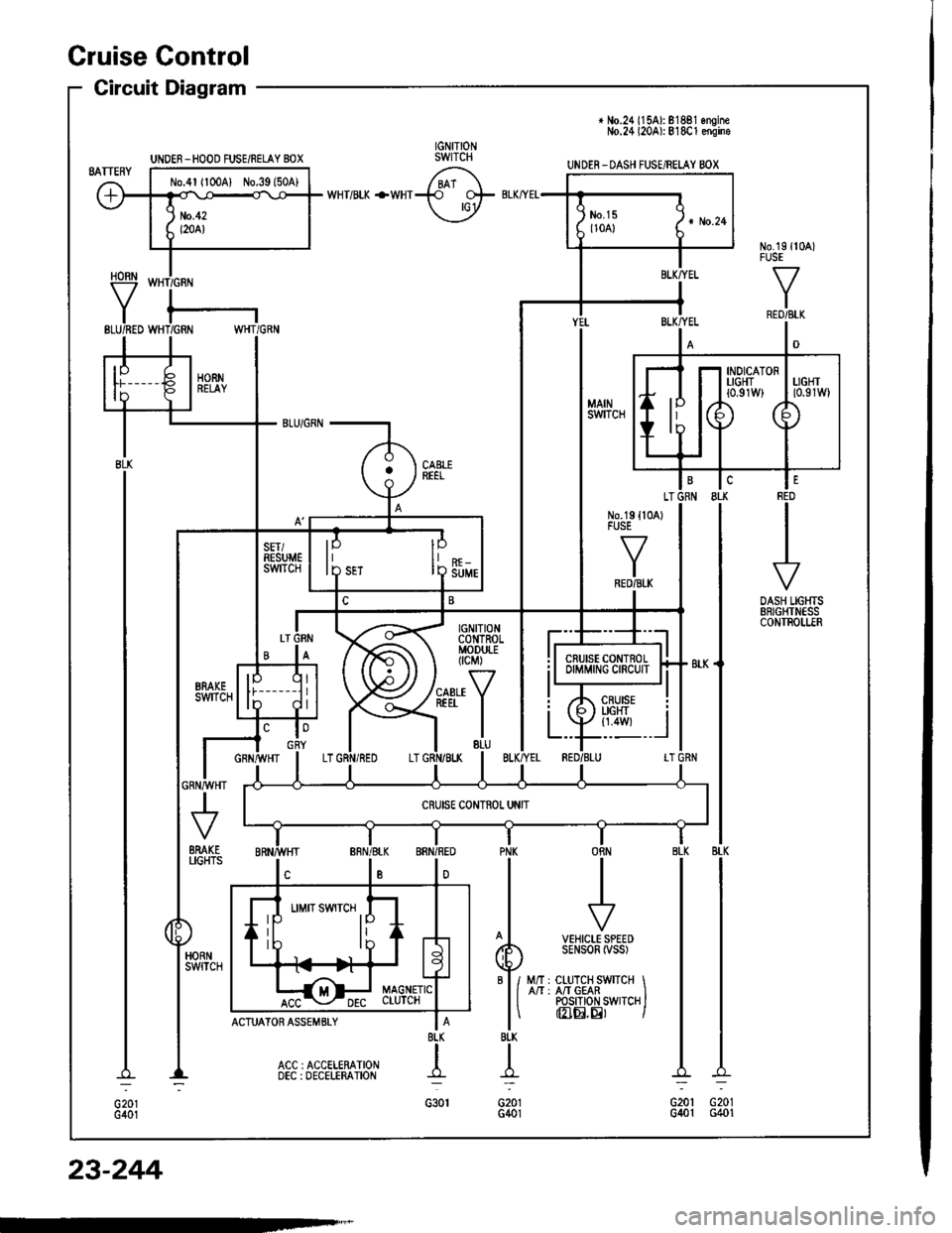
Cruise Gontrol
Circuit Diagram
23-244
Page 1351 of 1413
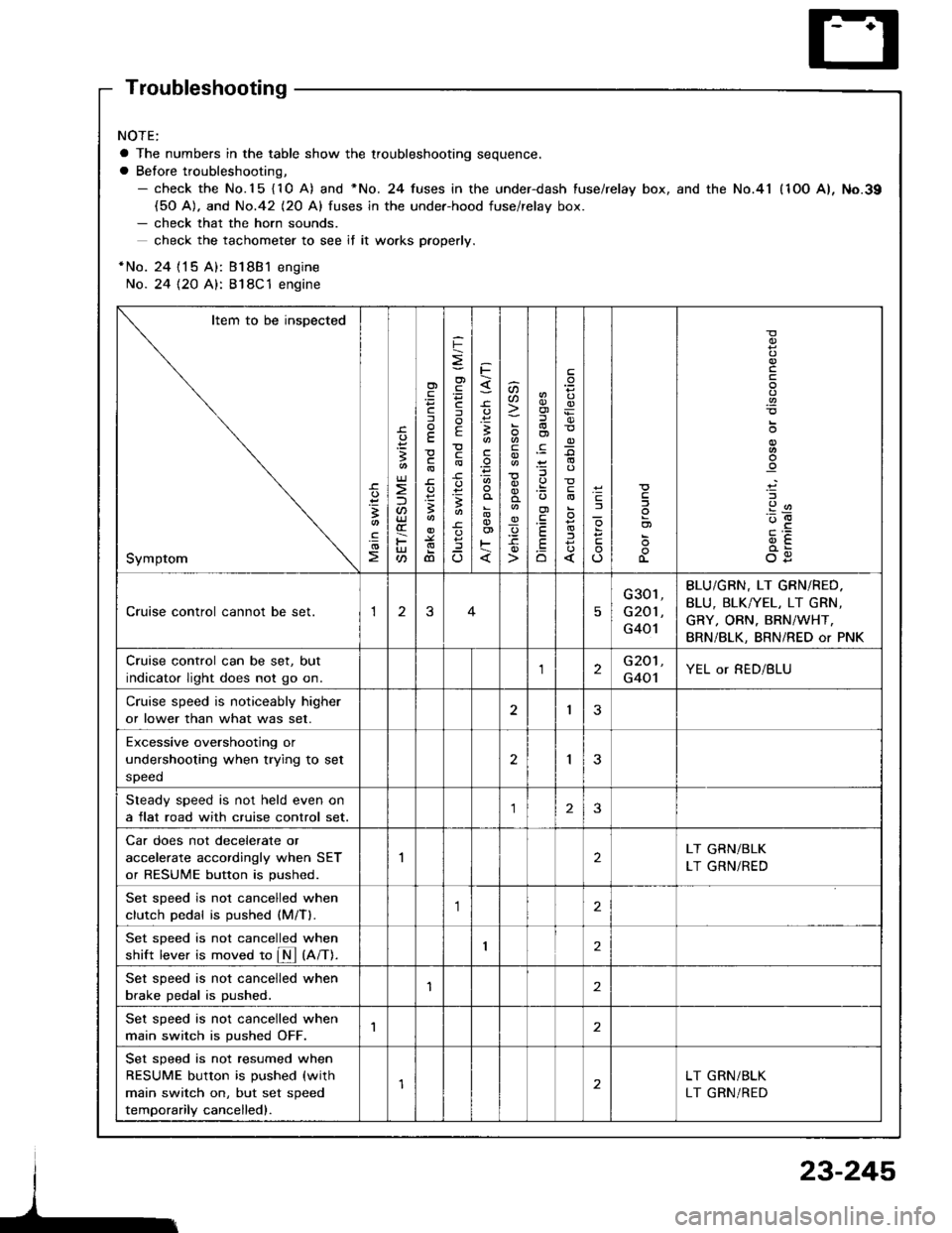
Troubleshooting
NOTE:
a The numbers in the table show the troubleshooting sequence.
a Before troubleshooting,- check the No.15 {10 A) and *No. 24 fuses in the under-dash fuse/relay box, and the No.41 (1OO A), No.39(50 A). and No.42 (20 Al fuses in the under-hood fuse/relav box.- check that the horn sounds.
check the tachometer to see if it wo.ks pfoperly.
*No. 24 {15 A): Bl8B1 engine
No. 24 {2O A}: 818C1 engine
Item to be inspected
Symptom
-c.
!I
.!o
;
U)
F
'Fcf
E
c
3
dl
F
o)
F
f
E
c
B
^
3
'.E
aa
_q
E
oi
.9:
E
.Eo
_9
l
If
L
!
.9
912'oE
og
Cruise control cannot be set.13
G301,
G201 ,
G401
BLU/GBN, LT GRN/RED.
BLU, BLK/YEL, LT GRN,
GRY, ORN. BRN/WHT,
BRN/BLK, BRN/RED or PNK
Cruise control can be set, but
indicator light does not go on.2G201,
G401YEL or RED/BLU
Cruise speed is noticeably higher
or lower than what was set.I3
Excessive overshootjng or
undershooting when trying to set
speed
2I
Steady speed is not held even on
a flat road with cruise control set.23
Car does not decelerate or
accelerate accordingly when SET
or RESUME button is pushed.
2LT GRN/BLK
LT GRN/RED
Set sDeed is not cancelled when
clutch Dedal is oushed (M/Tl.,1
Set sDeed is not cancelled when
shift lever is moved to fM tnnt.I2
Set speed is not cancelled when
brake pedal is pushed.'I2
Set speed is not cancelled when
main switch is pushed OFF.1
Set speed is not resumed when
RESUME button is pushed (with
main switch on, but set speed
temporarily cancelled).
LT GRN/BLK
LT GRN/RED
23-245
Page 1403 of 1413
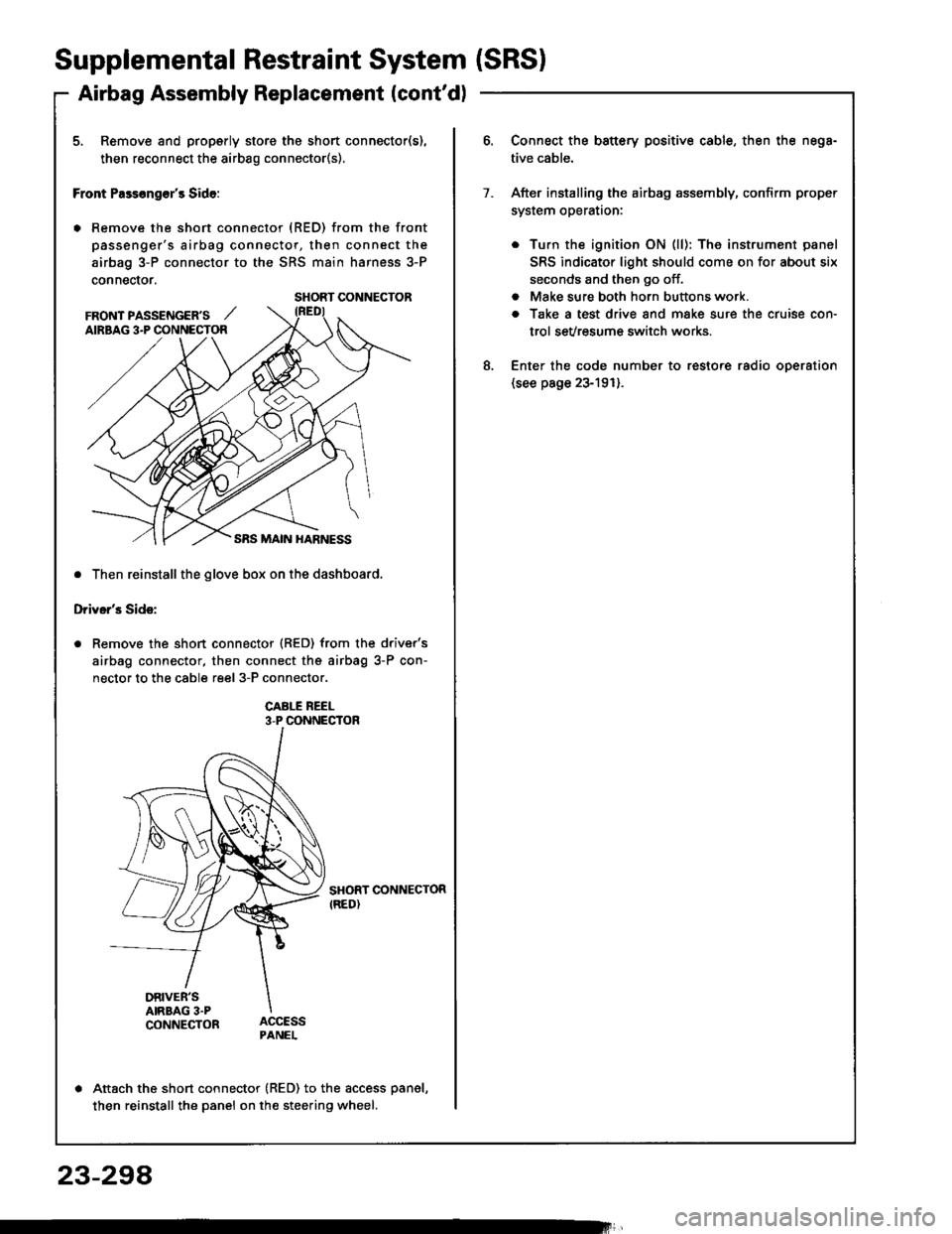
Supplemental Restraint System (SRSI
Airbag Assembly Replacement (cont'd)
5. Remove and properly store the short connector(s),
then reconnect the airbag connector(s).
Front Pass€ng€r's Side:
. Remove the short connector (RED) from the front
passenger's airbag connector, then connect the
airbag 3-P connector to the SRS main harness 3-P
connector.
. Then reinstall the glove box on the dashboard,
Driver's Side:
Remove the short connector (RED) from the driver's
airbag connector, then connect the airbag 3-P con-
nector to the cable reel 3-P connector.
CABI-E REEL3-P CONNECTOR
SHORT CONNECTORIRED)
DRIVER'SAIRBAG 3.PCONNECTOR
Attach the short connector (RED) to the access panel,
then reinstall the panel on the steering wheel.
SHORT CONNECTOR
FRONT PASSENGER'S ,,'AIRBAG 3.P CONNECTOR
Connect the battery positive cable, then the nega-
tive cable.
After installing the airbag assembly, confirm proper
system operataon:
. Turn the ignition ON (ll): The instrument panel
SRS indicator light should come on for about six
seconds and then go off.
. Make sure both horn buttons work.
a Take a test drive and make sure the cruise con-
trol sevresum€ switch works.
Enter the code number to restore radio oDeration(see page 23-191).
7.
8.
23-294
Page 1407 of 1413
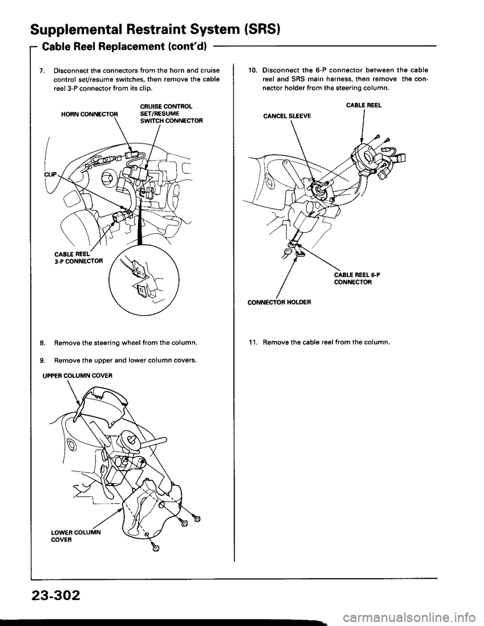
Supplemental Restraint System (SRSI
Gable Reel Replacement (cont'd)
Disconnect the connectors from the horn and cruise
control sevresume switches, then remove the cable
reel 3-P connector from its cliD.
8. Remove the steering wheel from the column.
9. Remove the upper and lower column covers.
UPPER COLUMN COVER
23-302
10.Disconnect the 6-P connector between the cable
reel and SRS main harness, then remove the con-
nector holder from the steering column.
'l l. Remove the cable reel from the column,
CABIT BEEL
CONNECTOF HOI-DER
Page 1408 of 1413
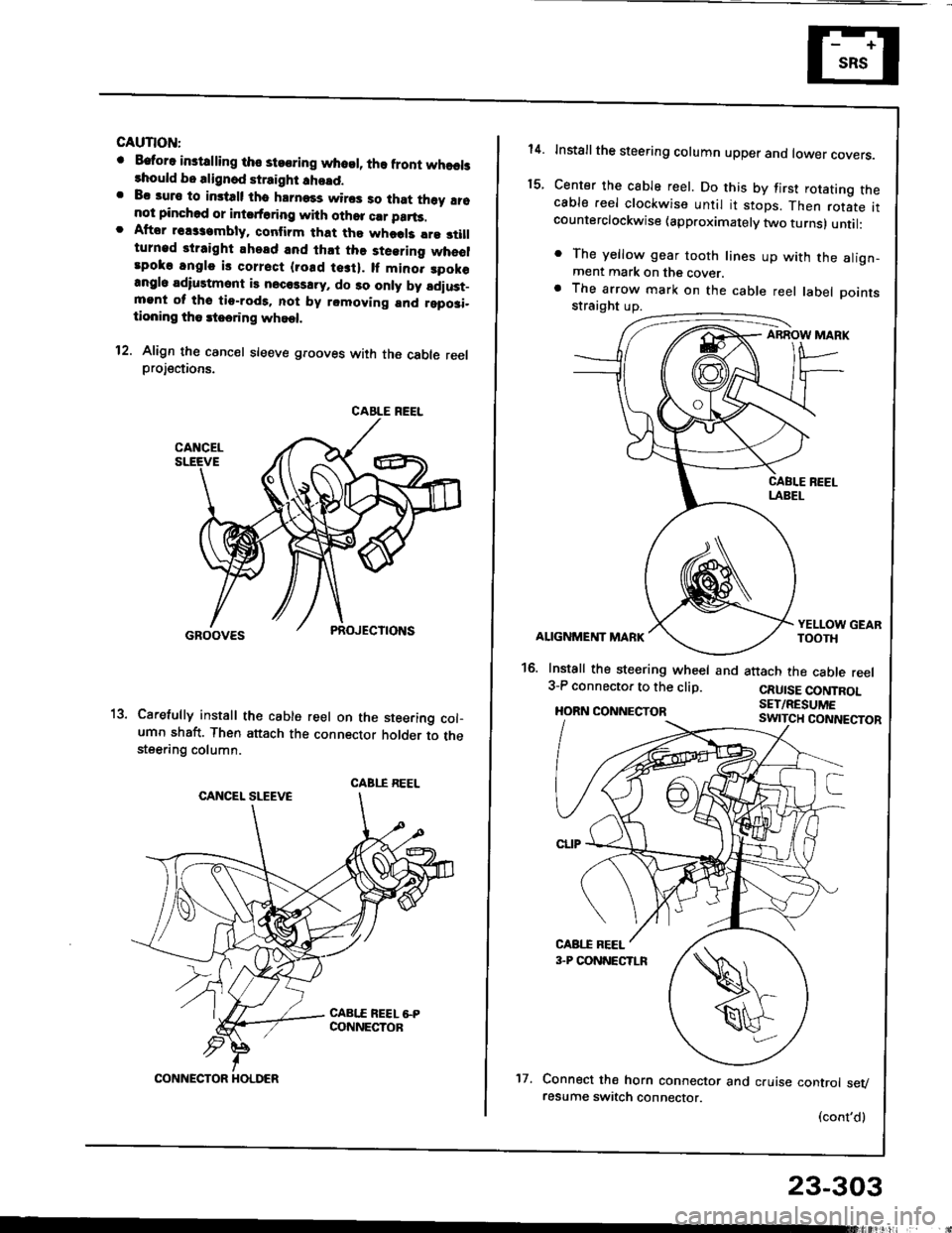
GAUTION:
o Eatora instdling tho steoring whosl, lha front whaelslhould bo alignod straight !ho!d.. Bc auro to imtalt tho hrrnass wiros so that th6y !16not pinchod or intsrt6ring with othor crr parts.. Aftor rsassambly. conlirm that tho whods lre 3tillturnad straight ahead and lh.t the steering wheolrpoko angle is corrsct {rosd tesi}. lf mino. spok€angl6 adiustmont is necols!ry, do 30 only by ldiust_mgnt ol tho tio-rod9. not by removing and rgposi-tioning tho rteering whoel.
12. Align th€ cancel sleeve grooves with the cable reelprojections.
Carefully install th€ cable reel on the steering col-umn shaft. Then attach the connector holder to thesteering column.
CABLE REEL
CABI.I REEL
CONNECTOR HOLDER't7.
23-303
14.
t5.
Installthe steering column upper ano tower covers.
Center the cable reel. Do this by first rotating thecable reel clockwise until it stops. Then rotate itcounterclockwise (approximately two turns) until:
. The yellow gear tooth lines up with the align-ment mark on the cover.a The arrow mark on the cable reel label Dointsstraight up.
ABROW MARK
ALIGNMENT MARK
16. Install the steering wheel and3-P connector to the clip.
HORN CONNECTOR
YELLOW GEARTOOTH
attach the cable reel
CRUISE CONTROLSET/RESUME
Connect the horn connector and cruise control sevresume switch connector.
(cont'd)
Page 1409 of 1413
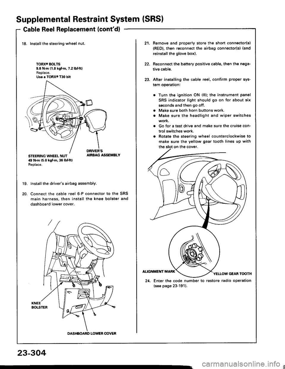
Supplemental Restraint System {SRSI
Cable Reel Replacement (cont'd)
18. Installthe steering wheel nut.
TORXO BOLTS9.8 N.m (1.0 kgf.m,7.2lbtftlReplace.Us6 a TORX6 T30 bit
STEERING WHEEL NUT,19 N.m 15.0 kgt m, 36 lbt ft)Replace.
AIRBAG ASSEMBLY
19.
20.
Install the driver's airbag assembly.
Connect the cable reel 6-P connactor to the SRS
main harness, then install the knee bolster and
dashboard lower cover.
DASHBOARD LOWER OOVER
21.Remove and properly store the shon connector(s)
{RED}, then reconnect the airbag connector(s} (and
reinstall the glove box).
Reconnect the battery positive cable, then the nega-
tive cable.
After installing the cable reel, confirm proper sys-
l€m operalron:
Turn the ignition ON (ll); the instrument panel
SRS indicator light should go on for about six
ssconds and then go off.
Make sure both horn buttons work.
Make sure the headlight and wiper switches
work.
Go for a test drive and make sure the cruise con-
trol switches work.
Rotate the steering wheel counterclockwise to
make sure the yellow gear tooth lines up with
22.
23.
a
a
24. Enter the code number to restore radio operation
(see page 23-191).
23-304