heater ACURA INTEGRA 1994 Service Owner's Manual
[x] Cancel search | Manufacturer: ACURA, Model Year: 1994, Model line: INTEGRA, Model: ACURA INTEGRA 1994Pages: 1413, PDF Size: 37.94 MB
Page 1039 of 1413
lllustrated Index
CAUTION:
a All SRS electrical wiling harnesses are covered with
y€llow insulation.
a Bafore disconnecting any pan of the SRS wile har-
ness. connect the sholt connectorlsl.
a Replace the sntire aflected SRS halness assembly if
it has an open circuit or damaged wiring.
NOTE: The original radio has a coded thelt protection
circuit. Be sure to get the customer's code number before- disconnecting the battery.- removing the No. 32 (7.5 Al fuse lrom the under-
hood fuse/relav box.- removing the radio.
After service, reconnect power to the radio and turn it
on. when the word "CODE" is displayed, enter the cus-
tomer's 5-digit code to restore radio operation.
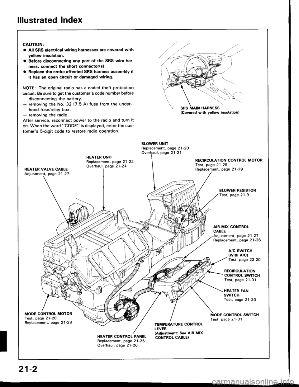
BLOWER UNITReplacement, page 21-2OOverhaul, page 21-21HEATER UNITRepfacement, page 2l 22Overhaul, page 21-24
RECIRCULATION CONTROL MOTORTest, page 21-29Replacement, page 21 29I{EATER VAIVE CABLEAdjustment, page 21-27
BLOWEN RESISTORTest, page 21-9
AIR MIX CONTROLCABLEAd,ustment, page 21-27Replacement. page 21-26
a/c swrTcH(wirh A/clTest, page 22-20
RECIRCULATIONCONTROL SWITCHTest, page 21-31
HEATER FANswtTcHTest, page 2'l-3O
MODE CONTROL MOTORTest, page 21-28Repfacement, page 21'28
MODE CONTROL SWITCHTest, page 21'31
HEATER CONTROL PANELRepf acement, page 21 -25
Overhaul, page 21-26
TEMPERATURE CONTROLLEVER(Adjustmonl: See AIR MIXCONTROL CABLE}
SRS MAIN HARNESS
W,
21-2
I
Page 1040 of 1413
Heater Door Positions
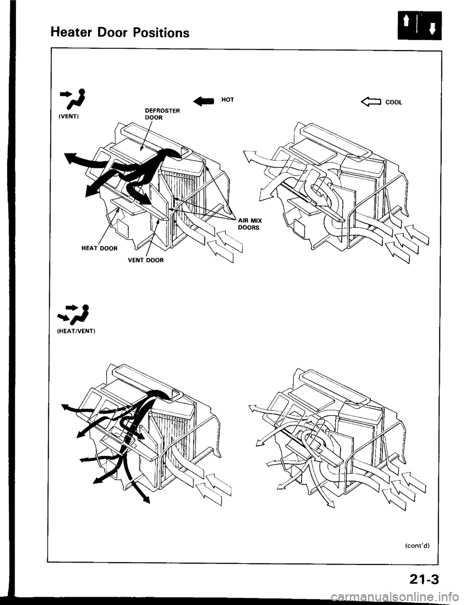
*)
! xorfr coor.
-*)
(HEAT/VENTI
(cont'd)
VENT OOOR
21-3
Page 1041 of 1413
Heater Door Positions
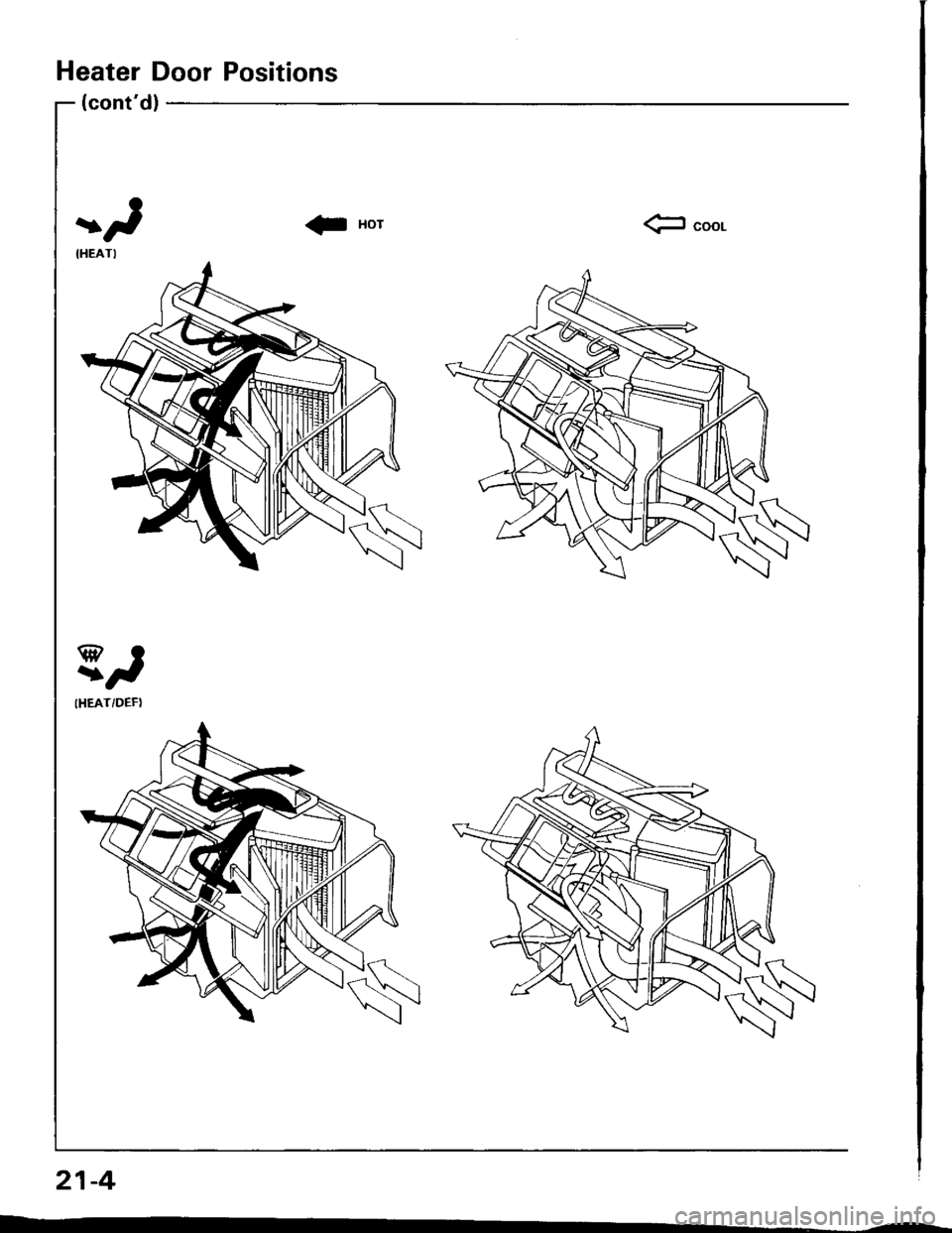
(cont'd)
)
IHEATI
El
IHEAT/DEF)
Page 1044 of 1413
I r.l. A.t tA_ A_r rA. A_r rA. A-l| | I lt I I -lt | -l -f | | -l -lr
rt,/ ,f rr,/ ,/ tt f ,f tt,/ ,f II tv v I rv v I rv v I rv v I
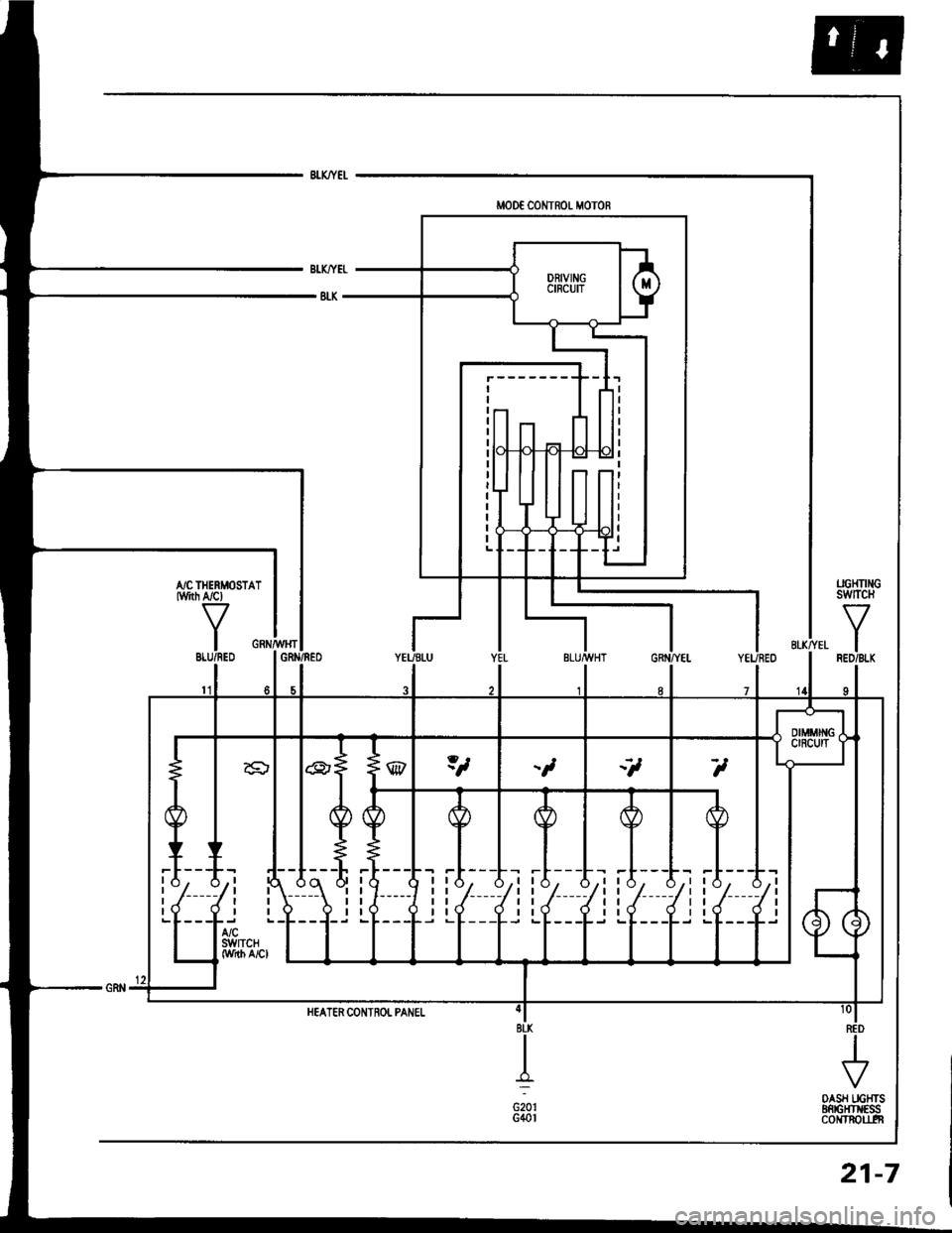
UGHTI GswtTcH
IRED/BI.K
OASH IIGTTTSEnrGFr ESScoNTROU.IT
HEATER CONTROL PANEI.
21-7
Page 1045 of 1413
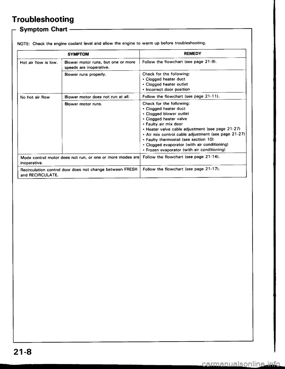
Troubleshooting
Symptom Chart
NOTE: Check the engine coolant level and allow the engine to warm up before troubleshooting.
SYMPTOMREMEDY
Hot air flow is low.Blower motor runs, but one ol more
speeds are inoperative.
Follow the tlowchart (see page 21-9).
Blower runs properly.Check for the following:. Clogged heater duct. Clogged heater outlet. Incorrect door position
No hot air JlowBlowel motor does not run at all.Follow the flowchart (see page 2l-l1l
Blower motor runs.Check for the following:. clogged heatet duct. Clogged blower outlet. Clogged heater valve. Faultv air mix door. Heater valve cable sdjustment lsee page 2'l-271
. Air mix control cable adjustment (see page 21-27)
. Faulty thermostat (see section lO)
. Clogged evaporator (with air conditioning). Frozen evaporator (with air conditioning)
Mode control motor does not run, or one or more modes are
inooerative.
Follow the flowchart (see page 21-14).
Recirculation control door does not change between FRESH
and RECIRCULATE.
Follow the flowchart (see page 21- 17).
21-A
Page 1046 of 1413
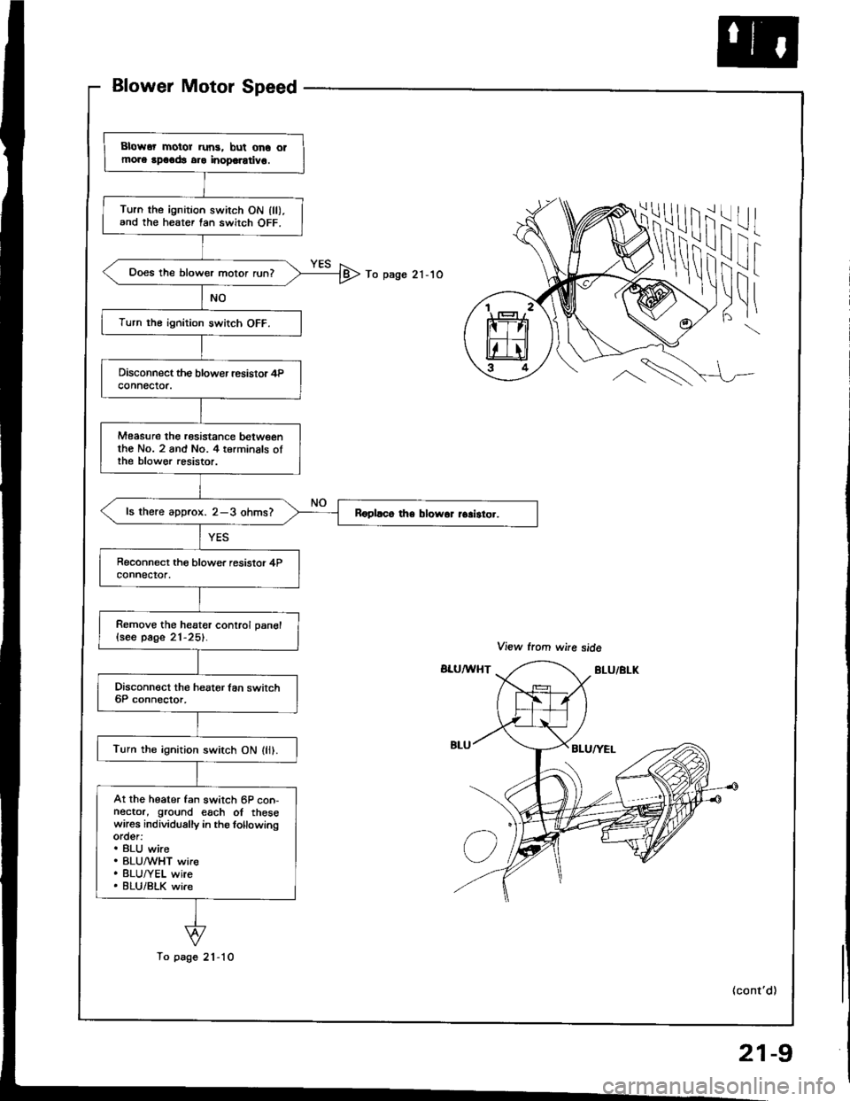
Blower Motor Speed
iii
I!i
-l
I
To pago 21-1O
l|t|
\
\
Blowor motor run3, bul ono olmors rpoodt aro inoporotivo.
Turn the ignition swirch ON lll).and the heater tan switch OFF.
Does the blower motor run?
Turn the ignition switch OFF.
Measure the rosistance betwoenthe No. 2 and No. 4 terminals oIthe blow€r resistor.
ls there aDorox. 2-3 ohms?
Remove the heater conlrol pan€l{seo page 21-25}.
Turn the ignition switch ON (li).
At the heater fan switch 6P con-nector, ground each of thesewares individually in ths lollowingorder:. BLU wire. BLUMHT wir€. BLU/YEL wire. 8LU/BLK wi.e
To page 21-10
(cont'd)
21-9
Page 1047 of 1413
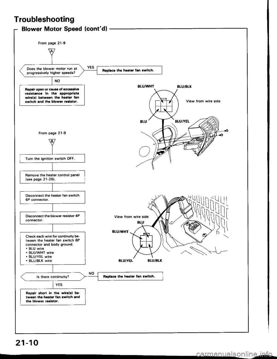
Does the blower motor run atprogressively higher speeds?Raplaca tho hollar fan rwitch.
Ropair opon or cau36 ol oxcoalivtrosbtanco in tho appaopaiatowire(3| b6twoon thg hostct lanswitch and tho blower todstor.
Turn the ignition switch OFF.
Remove the heater control panel(see page 21-25).
Check each wire for continuity be-tween the heater tan switch 6Pconnector and body ground.. BLU wire. BLUMHT wire. BLU/YEL wke. BLU/BLK wire
Raplaca tha haater lan awltch.
Bopair shon in the wir6{s} b€-lwo€n lho heatot lan switch rndth6 blowor ro3bto?.
From page 21-9
From page 21-9
View trom whe side
ilil
!\i
-l
I
View from wire side
BLU/U,HT
Troubleshooting
Blower Motor Speed (cont'd)
21-10
--
Page 1049 of 1413
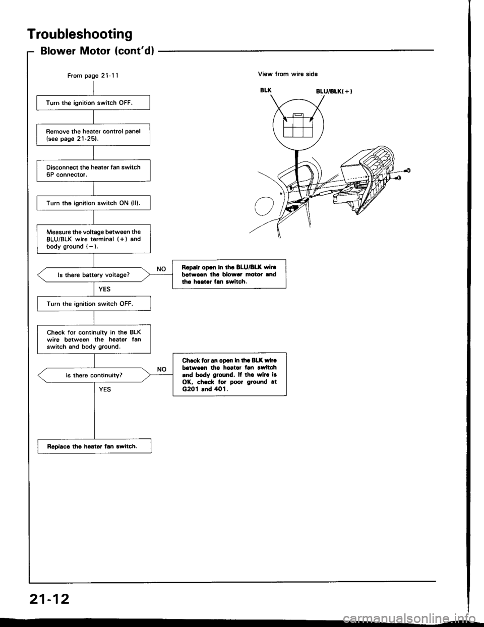
From page 21-11
Turn the ignition switch OFF.
Remove the heater control pan6l(see page 21-25).
Turn the ignition switch ON (lll.
Measure the voltage b€twsen the8LU/BLK wire terminal l+) andbody ground {- ).
Rgp.lr op.n In lh. BLU/BLK wh.batwoen lh! blowar motor lndtho hcolar f.n .wltch.ls there battory voltage?
Turn the ignition switch OFF.
Check tor continuity in lhe BLKwire between the heater lanswitch and body ground.
Ch.ck tor an opan in lhr Bl-K wirobdtwaan tho hortar tln lwftch.nd body ground. lf tho wlra l.OK, ch.ck for poor ground .tG201 .nd /rO1.
Roplaco tho hsator tan lwitch.
Troubleshooting
Blower Motor (cont'dl
View trom wire side
BLU/BLK{ + }
21-12
Page 1052 of 1413
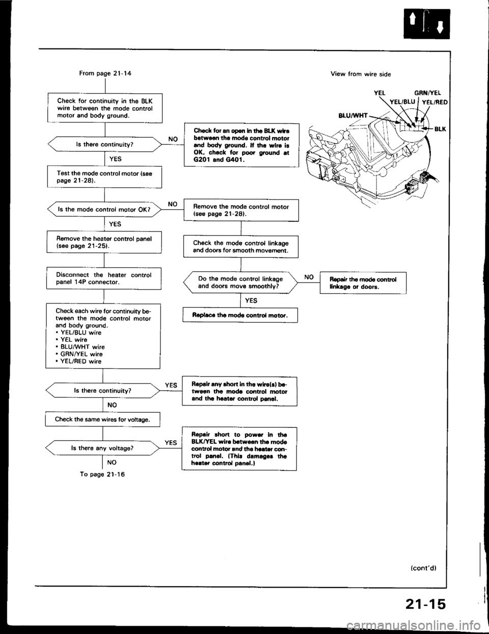
From page 21-14
NO
To psg6 2'l - 16
Check for continuity in the BLKwire betweon the mode controlmotor and body ground.
Chock lor an op6n In tho BLK wtbotwo€n tho modo control mototlnd body ground. It thr wlro i!OK, chock for poo. grouhd otG2O1 8nd G/tOl.
Test the modo control motor (seepage 21-281.
Romovo the mode control motor(soo pag6 21-281.ls the mode control motor OKI
Remove the heater control oanel{soe page 21-25).Ch€ck the modo control linkagoand doo.s tor smooth movoment.
Disconnect the heater controlDanel 14P connector.Do tho mode control linkageand doorc movs smoothlv?Ropair th6 mod6 controllinkago or doors.
Ch€ck each wire for continuity bo-twoon the mod6 control motorand body ground.. YEL/BLU wire. Y€L wire. 8LU,^/VHT wire. GRNI/EL wire. YEL/RED wire
Raplace thc modo control moto..
Roprir any .hort in th. wlrol!) b.-tworn tha moda control anototand tha holtar control pan6l.
Check the same wires lor vohage.
Roplir rho.t to powar In tha8LK^'EL wiro b.two.h lh. modoconlrol hotor rnd tha haat* con-trol p!rr.|. (Thi! damrg.. thahello. control p!nel.)
ls the.6 any voltage?
View lrom wi.e side
GRl{/YEL
lconl'dl
21-15
Page 1053 of 1413
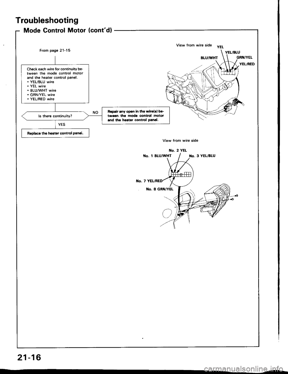
View from wire side yELFrom page 21-'l 5
Check each wire for conlinuity be-tween the mode contiol motorand the heater control panel.. YEL/BLU wire. YEL wire. BLU/WHT wire. GRN/YEL wire. YEL/RED wire
R.psir any opon in fro wir6{.1 bo-twocn tho mod€ control motolsnd tho holtar contiol prnal.
Rsploco tho hoator conlrcl panol.
Troubleshooting
Mode Control Motor (cont'd)
21-16