engine ACURA INTEGRA 1994 Service Workshop Manual
[x] Cancel search | Manufacturer: ACURA, Model Year: 1994, Model line: INTEGRA, Model: ACURA INTEGRA 1994Pages: 1413, PDF Size: 37.94 MB
Page 115 of 1413
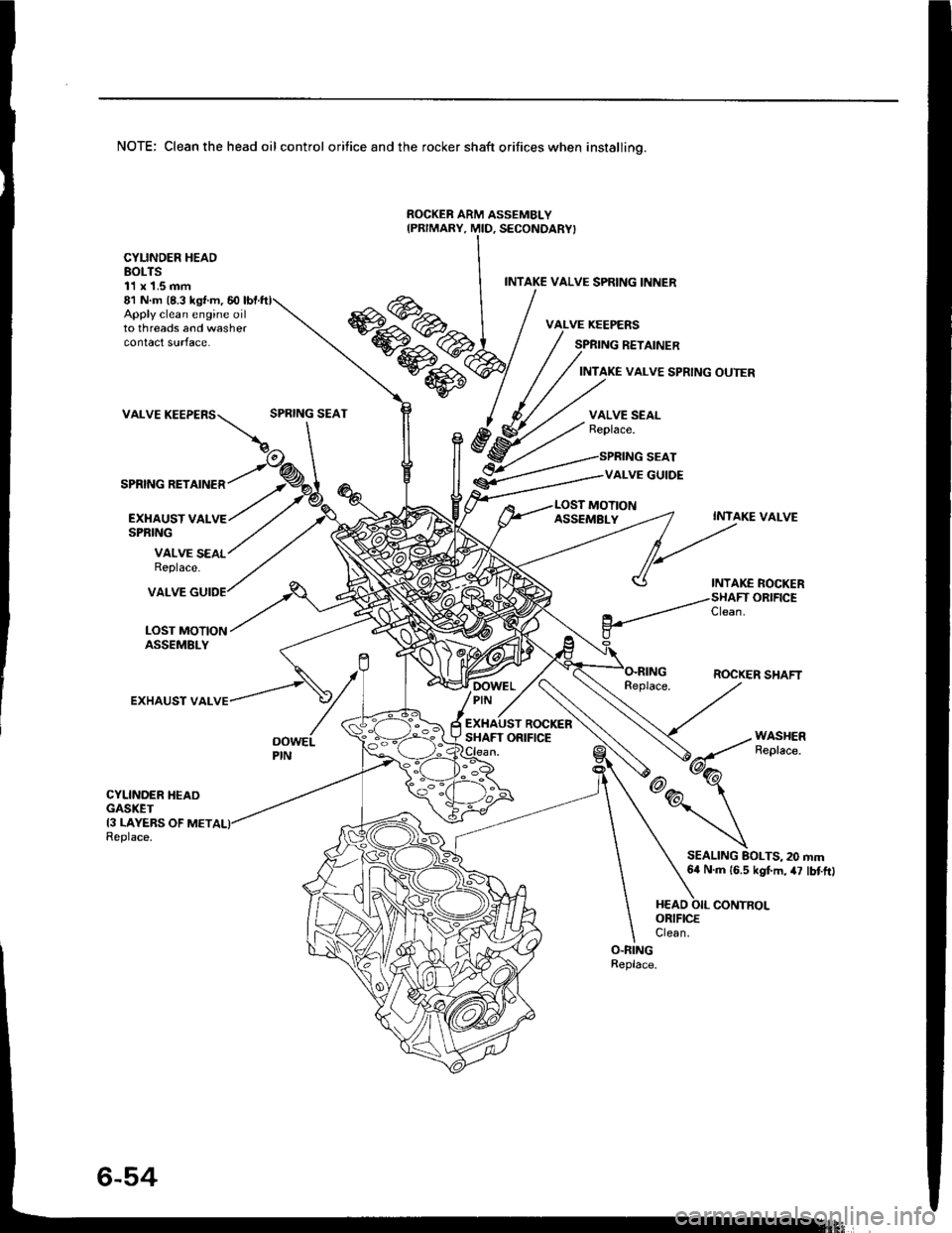
NOTE: Clean the head oil control orifice and the rocker shaft orifices when installino.
ROCKEB ARM ASSEMBLY
Apply clean engine oilto threads and washercontact surface.
81 N m (8.3 ks{ m, 60
VALVE
SPRING RETAINER
CYLINDER HEADBOLTS11 x 1.5 mm
EXI{AUST VALSPRING
INTAKE VALVE SPRING INNER
SPRING RETAINER
INTAKE VALVE SPRING OUTER
SPRING SEATVALVE SEALReplace.
SPRING SEAT
VALVE GUIDE
MOTION
VALVE SEALReplace.
ASSEMBLYINTAKE VALVE
INTAKE ROCKERORIFICE
LOST MOTIONASSEMBLY
VALVE
EXHAUST VAL
Clean.
ROCKER SHAFTDOWELPIN -,
ROCKERSHAFT ORIFICEOOWELPIN
CYLINDER HEAOGASKET13 LAYEBS OF METReplace.
SEALING BOLTS, 20 mm64 N.m 16.5 kgf.m, 47 lbtftl
Page 116 of 1413
Cylinder Head
Removal
Engine removal is not required or this procedure.
CAUTION: To avoid damaging tho cylinder head, wail
u[tilths.nginc coolant tsmperaturo drops bolow 100"F(38'Cl bafore loos6ning tho retaining bolts.
NOTE;
. Inspect the timing belt before removing the cylinder
head.
Turn the crankshaft pulley so that the No. 1 piston is
at top dead center (TDc) {page 6-51).
Mark all emissions hoses betore disconnecting them.
Anti-theft radios have a coded theft protection circuit.
Be sure to get the customer's code number before- Disconnecting the battery.- Removing the No.32 (7.5 A) fuse trom the under-
hood fuse/relay box.- Removing the radio.
After service, reconnect power to the radio 8nd turn it
on.
When the word "CODE" is displaved. enter the cus-
tomer's 5-digit code to restore radio operation,
Disconnect the negative terminal from the battery.
Drain the engine coolant (see page 10-5).
. Remove the radiator cap to speed draining.
Relieve fuel pressure (see section 111.
l@ Do not 3moke whilo working on fuel
a
a
'1.
systgm. ko6p opon tlamo ot Spark away trom work
aroa. Drain fugl only into an approved containsr,
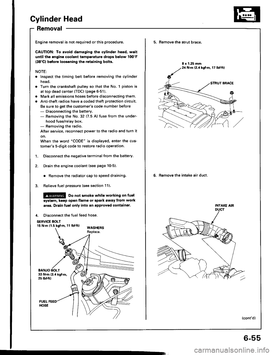
4. Disconnect the fuel feed hose.
SERVIC€ BOLT15 N.m (1.5 kgtm, rl bf.tt)WASHERSReplace.
BANJO BOLT
5. Remove th€ strut brace,
6. Remove the intake air duct.
8 x 1.25 mm24 N.m (2.1kg[.m, 17 lbtftl
INTAKE AIR
(cont'd)
6-55
Page 118 of 1413
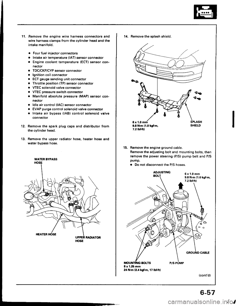
ll.Remove the engine wire harness connectors and
wi.e ha.ness clamps from the cylinder head and the
intake manitold.
Four fuel injector connectors
Intake air tempe.ature {lAT) sensor connector
Engine coolant temperature (ECT) sensor con-
nector
TDC/CKP/CYP sensor connector
lgnition coil conn€ctor
ECT gauge sending unit connector
Throttle position (TP) sensor connector
VTEC solenoid valve connector
VTEC Dressure switch connector
Manifold absolute pressure (MAP) sensor con-
nector
ldle air control {lAC) sensor connector
EVAP purge controlsol€noid valvo connector
Intake air bypass {lABl control solenoid valve
conneclor
a
o
a
o
a
a
a
a
a
a
a
a
a
12.
13.
Remove the spsrk plug caps and distributor from
the cylinder head.
Remove the upper radiator hose, heat€r hose and
water bypass hose.
WATER BYPASS
HOSE
6r1.0mm9.8 N.m (1.0 kgt m,1.2 tbtftl
14. Remove the sDlash shield.
Remove the engine ground cable.
Romovo the adjusting bolt and mounting bolts, then
remove the power steering (P/S) pump belt and P/Spump.
. Do not disconnect the P/S hoses.
(cont'dl
15.
6x1.0mm9.8 N.m 11.0 kgl.m,7.2 tbt.ttl
6-57
,l
Page 119 of 1413
Cylinder Head
Removal (cont'dl
Remove the heat shield from the P/S bracket (see
page 5-18).
Remove the air conditioning (Ay'Cl compressor belt(see page 6-49).
Remove the alternator belt {s€e page 6-49).
Remove the cruise control actuato..
16.
17.
'18.
'19.
ACTUATOR
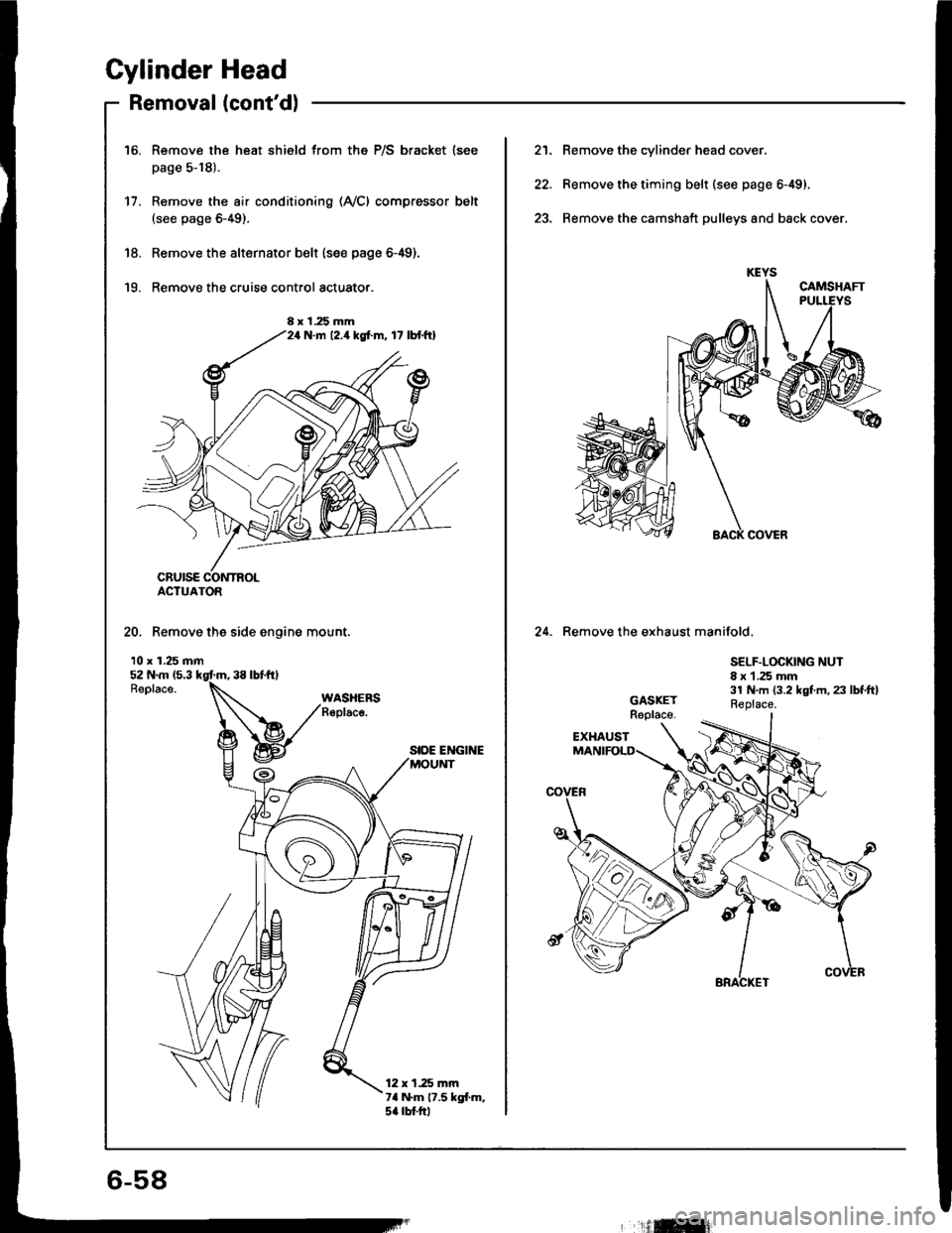
20. Remove the side engine mount.
10 x 1.25 mm
SIDE ENGINE
12 x 1.25 mrn7a N.m 17.5 kgl.m,5a rbtftl
8 x 1.25 mmN.m 12.4 kgf.m, 17 lbtftl
21. Remove the cylinder head cover.
22. Remove the timing belt (see page 6-49).
23. Remove the camshaft pulleys and back cover.
24. Remove the exhaust manifold.
SELF.LOCKING NUT8 x 1 .25 mm31 N.m {3.2 kgt m, 23 lbf.ftlReplace.
6-58
'ilffi{
Page 136 of 1413
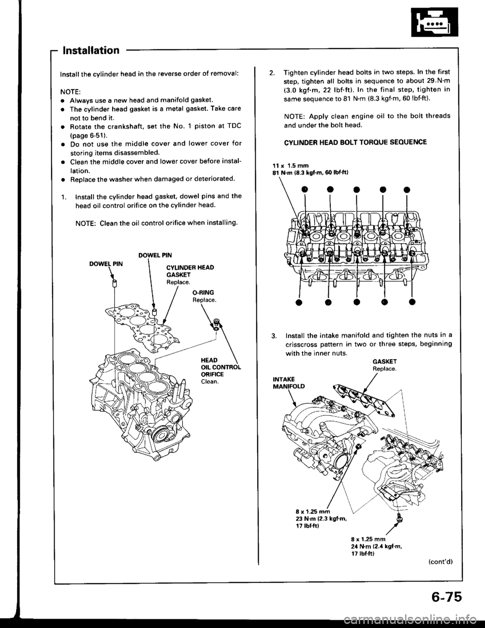
lnstallation
Installthe cylinder head in the reverse order of removal:
NOTE:
. Always use a new head and manifold gasket.
. The cylinder head gasket is a metal gasket Take care
not to bend it.
. Rotate the crankshaft, set the No. 1 piston at TDC
(page 6-51).
. Do not use the middle cover and lower cover for
storing items disassembled.
. Clean the middle cover and lower cover before instal-
lation.
a Replace the washer when damaged or deteriorated
1. tnstall the cylinder head gasket. dowel pins and the
head oil control orifice on the cylinder head
NOTE: Clean the oil control orifice when installing.
O.RINGReplace.
HEADOIL CONTROLORIFICECloan.
2. Tighten cylinder head bolts in two steps. In the first
step, tighten all bolts in sequence to about 29 N'm
(3.0 kgf.m.22 lbf'ft). In the final step, tighten in
same sequence to 81 N.m (8.3 kgnm.60 lbf'ft).
NOTE: Apply clean engine oil to the bolt threads
and under the bolt head.
CYLINDER HEAD BOLT TOROUE SEOUENCE
11 x 1.5 mm81 N.m {8.3 kgf.m,60 lbf ft)
Install the intake manifold and tighten the nuts in a
crisscross pattern in two or three steps, beginning
with the inner nuts.
GASKETRePlace
8 x 1.25 mm23 N.m 12.3 kgl.m.17 tbf.ftt
8 x 1.25 mm24 N,m 12.,4 kgf m,17 tbf.ft)(cont'd)
6-75
Page 139 of 1413
11.
12.
13.
Cylinder Head
Installation lcont'd)
lnstallthe timing belt lsee page 6-51).
Adjust the valve clearance (see page 6-44).
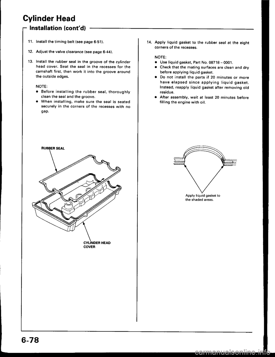
Install the rubber seal in the groove of the cylinder
head cover. Seat the seal in the recesses for the
camshaft first, then work it into the groove around
the outside edges.
NOTE:
. Before installing the rubber seal. thoroughly
clean the seal and the groove.
. When installing, make sure the seal is seatedsecurely in the corners of the recesses with nogap.
COVER
6-78
14. Apply liquid gasket to the rubbe. seal at the eightcorne.s of the recesses.
NOTE:
. Use liquid gasket, Part No. 08718 - 0001.. Check that the mating surfaces are clean and dry
before applying liquid gasket.
a Do not install the parts if 20 minutes or more
have elapsed since applying liquid gasket.
Instead,.eapply liquid gasket after removing oldresidue.
r After assembly, wait at least 20 minutes beforefilling the engine with oil.
Apply liquid gasket tothe shaded areas.
Page 141 of 1413
Engine Block
Speciaf Tools .............7'2
lllustrated Index ................................... 7-3
Flywheel and Drive Plate
Repfacement .........7-7
Main Bearings
Clearance ,.............. 7-8
Selection ................ 7-8
Connecting Rod Bearings
Clearance ............... 7-9
Selection ................ 7-9
Crankshaft
Removal .................7-10
End Play .................7-12
lnspection ........,,,.,,7-12
fnstallation .............7'22
Cylinder Block
Inspeetion ..............7-13
Bore Honing .....,.,,.7'14
Pistons
Inspaction ..............7-15
Installation .............7-16
Piston Rings
Replacement .........7-16
End Gap .................7-17
Ring-To-Groove C|earance,,,,.,,,...... 7 -17
Alignment ..............7-18
Piston Pins
Removal ........,........7-18
Installation (818B1 engine) ............. 7-19
fnstaffation (818C1 enginel ............. 7-20
fnspection ..............7-2O
Connecting Rods
End Play .................7-21
Sefeetion ..........,,,,,,7-22
Oil Seal
fnstaffation .............7-25
Installation
(engine removal not requiredl.. .......7-26
Page 143 of 1413
lllustrated Index
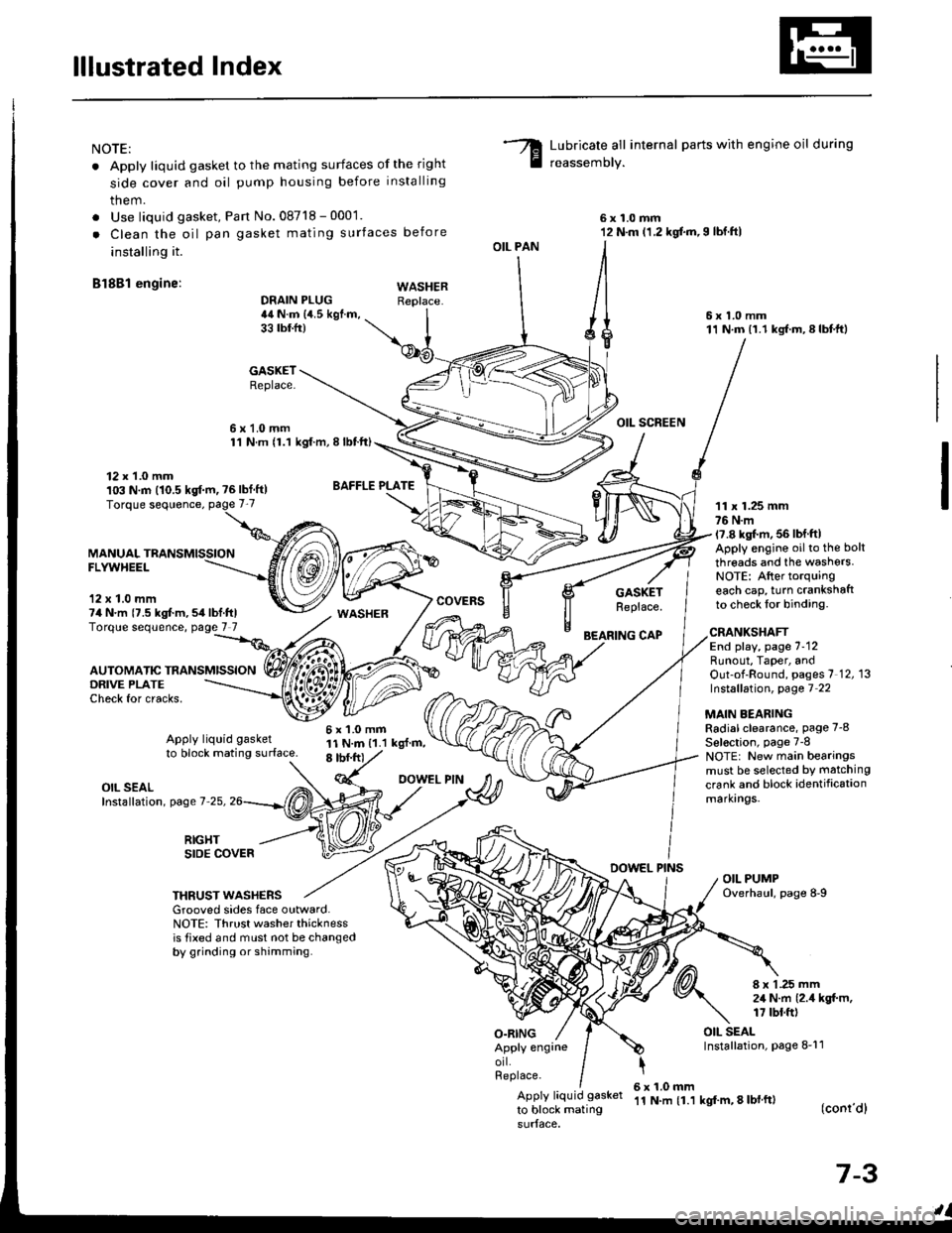
NOTE:
. Apply liquid gasket to the mating surfaces of the right
side cover and oil pump housing before installing
them.
. Use liquid gasket, Pan No.08718 - 0001.
. Clean the oil pan gasket mating surfaces before
installing it.
Bl8Bl engine: wAsHEF
Lubricate all internal parts with engine oil during
reassemory.
6x1.0mm12 N.m (1.2 kgf.m,I lbf.ftl
6x1.0mm11 N.m (1.1 kgf.m,8lbtft)
OIL SCREEN
11 x 1.25 mm76 N.m17.8 kgl.m, 56 lbf ftlApply engine oilto the bolt
threads and the washers.NOTE: After torquingeach cap, turn crankshaftto check lor binding.
DRAIN PLUG44 N.m {4.5 kgf.m,33 tbtfr)
GASKETReplace.
6x1.0mm1'l N.m {1.1 kgt.m, I lbtft)
OIL PAN
O.RING
GASKETReplace.
BEARING CAP
12 x 1.0 mm103 N.m (10.5 kgf.m, ?6lbf ft)
MANUALFLYWHEEL
'12 x 1.0 mm74 N.m {7.5 kgt m,54lbf.ftlTorque sequence, page 7 7
DRIVE PLATECheck for cracks,
AUTOMATIC TRANSMISSION
WASHER
6x1.0mm11 N.m {1.1 kgl.m,8 tbf.frt
CRANKSHAFTEnd play, page 7-12Runout, Taper, andOut-of-Round, pages 7 12, 13Instsllation, page 7 22
MAIN BEARINGRadial clearance, page 7-8
Sel€ction, page 7-8NOTE: New main bearingsmust be selected by matching
crank and block identificationmarkrngs.
Apply liquid gasket
to block mating surface.
OIL SEALInstallation, page 7-25,
RIGHTSIDE COVERDOWEL PINSOIL PUMPOverhaul, page 8-9THRUST WASHERSGrooved sides face outward.NOTE: Thrust washer thicknessis tixed and must not be changedby grinding or shamming.
8 x 1 .25 mm2,1 N.m {2.4 kgt m,17 tbt.ft)
OIL SEALInstallation, page 8-11Apply engrneorl.Replace.
Apply liquid gasket
to block mating
6x1.0mm'11 N.m {1.1 kgf'm, 8 lbl ft)(conr'dl
7-3
Page 144 of 1413
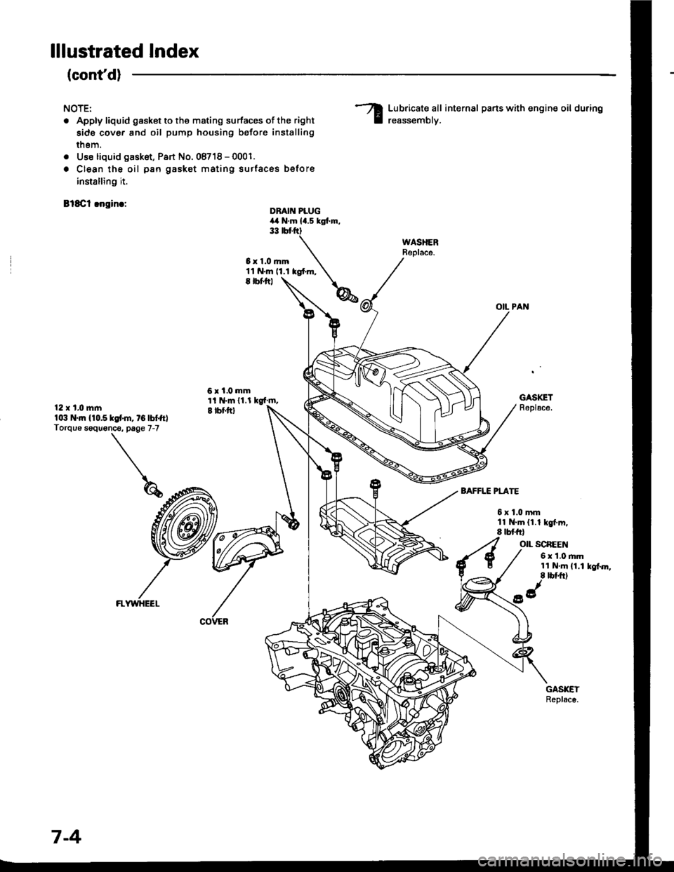
lllustrated Index
(cont'd)
NOTE:
. Apply liquid gasket to the mating surfaces of the right
side cover and oil pump housing before installing
thsm.
. Use liquid gask6t, Part No. 08718 - 0001.
. Clean the oil pan gasket mating surtac€s before
innalling it.
Bl8Cl !ngin.:
Lubricate all internal parts with engine oil during
reassemblv.
OIL PAN
DBAIN PLUG4,a N.m la.s tgl.m.33 rbr.ftt
6x1.0mm11 N.m (1.1 kgt m,E |bfitl
6x1.0mmti l*m 11.l kgf m,I tbf.ftl
GASKETReplace.12 x t.0 mlnlo:t N.|n 110.510f'm, tG lbffrlTorque soquonce. page 7-7
BAFFLE PLATE
6xl.0mmll N.m (1.1 kgt m.8 tbt frl
O|L SCAEEN
6 x 1.0 rim11 N.m (1.1 kgf.m,8 tbt ft)
FLWYHEEL
7-4
Page 145 of 1413
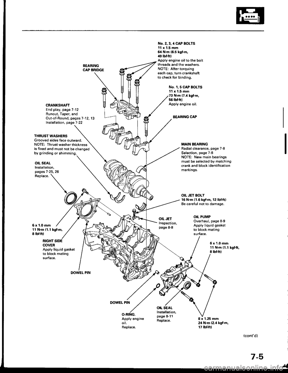
BEARINGCAP BRIDGE
No. a 3, /a CAP BOLTSll x 1.5 mm64 N.m {6.5 kgt m,49 tbf.ftlApply engine oilto tho boltthreads and the washers.NOTE: Aftertorquingeach cap, turn crankshaftto check for binding.
No. 1,5 CAP BOI-TS11 x 1.5 mm73 N.m {7.4 kgf.m,56 tbt'ft|Apply engine oil.
BEARING CAP
CRANKSHAFTEnd play, page 7-12Runout, Taper, andOut-of-Round, pages 7'12. 13Installation, page 7-22
YHRUST WASHERSGrooved sides lace outward.NOTE: Thrust washer thicknessis fixed and must not be chano€d
MAIN BEARINGRadial clearance. page 7 8S6l€ction, page 7-8NOTE: New main bearingsmust be selected by matchingcrank and block identificationmarxrngs.
OIL JEI BOLY16 N.m 11.6 kg{'m, 12lbtftlBe caretul not to damage.
OIL PUMPOverhaul, page 8-9Apply liquid gasket
to block matingsurface.
OIL SEALInstallation,pages 7-25, 26
11 N.m 11.1 kgt m,8 lbf ftl
Replace.
6r1.0mm
OIL JETInspection,page 8-8
OIL SEALInstellelion,page 8-11Replace.
RIGHT SIDECOVERApply liquid gasketto block matingsurface.
6x1.0mm11 N.m {1.18 rbf.ftlkSf.ft,
DOWEL PIN
DOWEL PIN
O.RING.Apply engineorl.Replace.
8 x 1.25 mm24 N.m {2.4 kgt m,17 tbtft)
(cont'd)
7-5