torque ACURA INTEGRA 1994 Service Manual PDF
[x] Cancel search | Manufacturer: ACURA, Model Year: 1994, Model line: INTEGRA, Model: ACURA INTEGRA 1994Pages: 1413, PDF Size: 37.94 MB
Page 553 of 1413
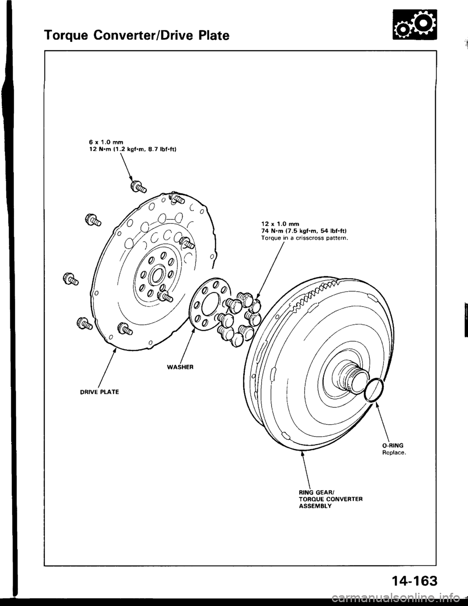
Torque Converter/Drive Plate
6 x'l.O mm12 N.m {1.2 kgf.m, 8.7 lbf'tt)
12 x 1.0 mm74 N.m {7.5 kgf.m, 54 lbl.ftlTorque in a crisscross pattern.
0
0d
DRIVE PLATE
TOROUE CONVERTERASSEMELY
14-163
Page 554 of 1413
Transmission
Installation
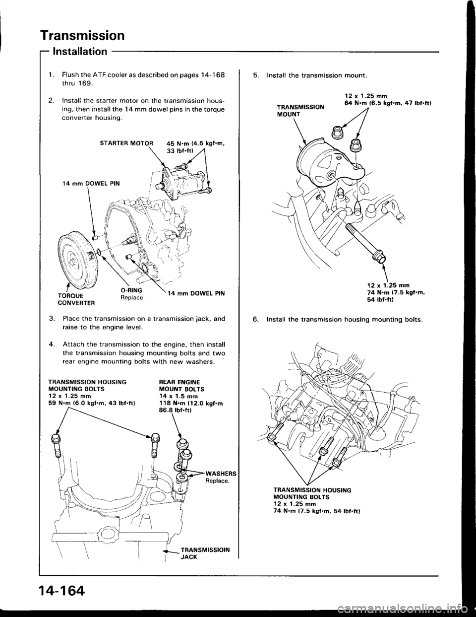
1. Flush the ATF cooler as described on pages I4-168
thru 'l 69.
2. Install the starter motor on the transmission hous-
ing, then installthe l4 mm dowel pins in the torque
converrer nousrng.
STARTER MOTOR
O-RINGReplace.14 mm OOWEL PINTOROUECONVERTER
J.
TRANSMISSION HOUSINGMOUNTING BOLTS
59 N.m 16.0 kgf.m,43 lbl.ftl
Place the transmission on a transmission jack, and
raise to the engine level.
Attach the transmission to the engine, then install
the transmission housing mounting bolts and two
rear engine mounting bolts with new washers.
REAR ENGINEMOUNT BOLTS14 x 1.5 mm
45 N.m 14.5 kgf'm,
'14 mm DOWEL PIN
I
i.'l,i;
14-164
5. Install the transmission mount.
6. Install the transmission
12 x 1.25 mm64 N.m 16.5 kgl.m, 47 lbf.ft)
12 x 1.25 mm74 N.m 17.5 kgf'm,54 rbt'ft)
housing mounting bolts.
MOUNTING BOLTS12 x 1 .25 rnm74 N.m (7.5 kgf'm, 54 lbf.ftl
TRANSMISSION HOUSING
Page 555 of 1413
7.Remove the transmission jack.
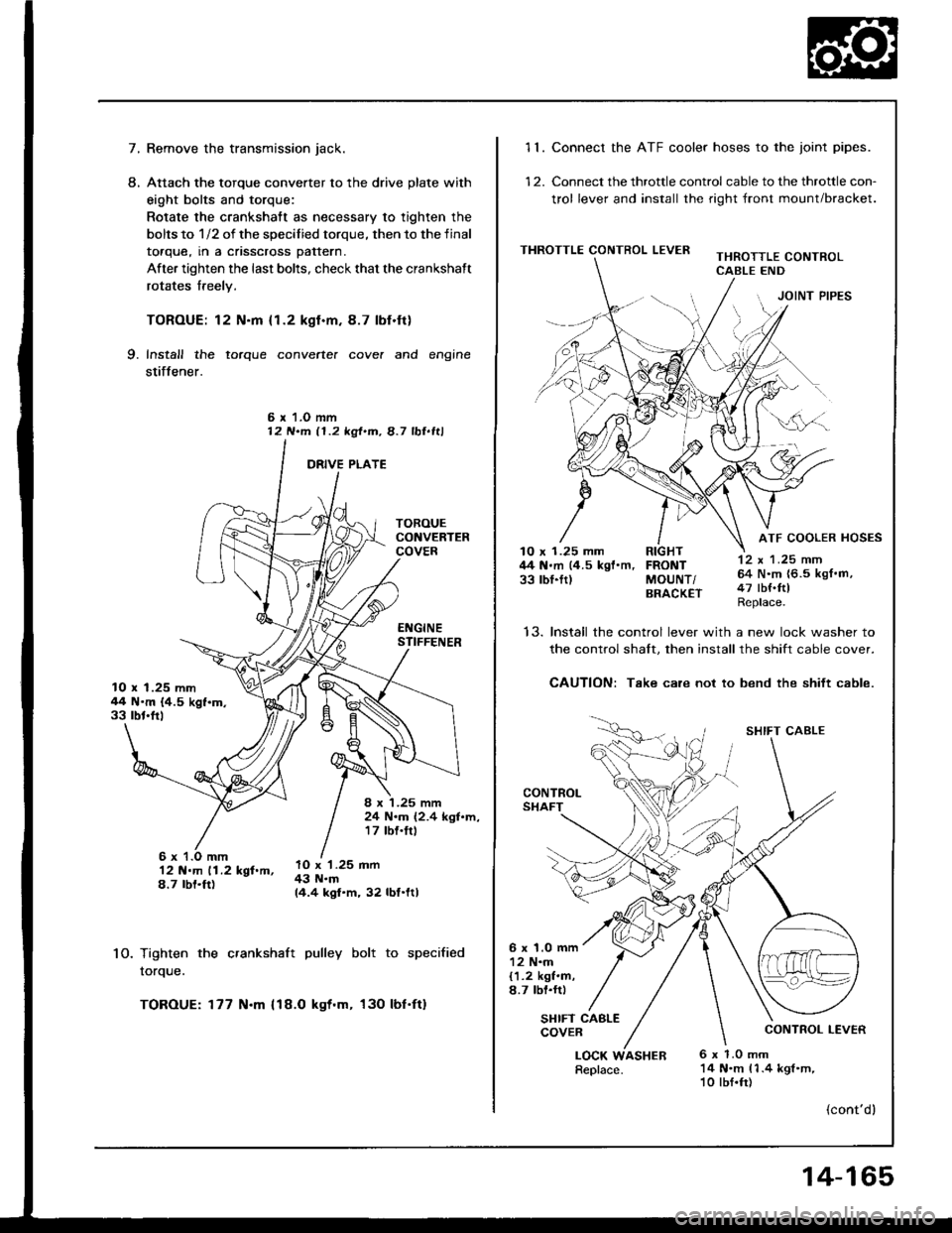
Attach the torque converter to the drive plate with
eight bolts and torque:
Rotate the crankshatt as necessary to tighten the
bolts to 1/2 of the specilied torque, then to the final
toaque, rn a cnsscross pattern.
After tighten the last bolts, check that the crankshaft
rotates freely.
TOROUE: 12 N.m {1.2 kgl.m.8.7 lbf.ft}
Install the torque converte. cove. and engine
stiffener.
L
9.
6 r 1.O mm12 N.m 11.2 kgt.m, 8.7 lbl.ltl
10.
12 N.m 11.2 kgf.m,8.7 rbt.ft)
Tighten the crankshaft pulley bolt to specified
rorque.
TOROUE: 177 N.m {18.O kgt.m, 130 lbf'ft}
10 x 1.25 mm44 N'm {4.5 kgf.m.33 rbt'frl
8 x '1.25 mm24 N.m (2.4 kgl.m,17 tbf.trl
lO x '1.25 mm43 N.m14.4 kgf.m, 32 lbf.ltl
11. Connect the ATF cooler hoses to the joint pipes.
12. Connect the throttle control cable to the throttle con-
trol lever and install the right front mount/bracket.
THROTTLE CONTROL LEVERTHROTTLE CONTROLCABLE END
JOINT PIPES
12 x 1 .25 mm64 N.m {6.5 kgf.m,47 tbf.ftlReplace.
ATF COOLER HOSES10 x 1.25 mm RIGHT44 N.m (4.5 kgf'm, FRONT33 rbl.ftl MoUNT/BRACK€T
t5.Install the control lever with a new lock washer to
the control shalt. then install the shift cable cover.
CAUTION: Take care not to bend the shift cable.
CONTROLSHAFT
SHIFT CABLE
CONTROL LEVER
6 x 1.0 mm12 N.m{1.2 kgf.m,8.7 lbl.rr)
SHIFT CABLECOVER
LOCK6 x 1.0 mm14 N.m 11.4 kgl.m,10 lbf.fr)
(cont'dl
Replace.ASHER
14-165
Page 582 of 1413
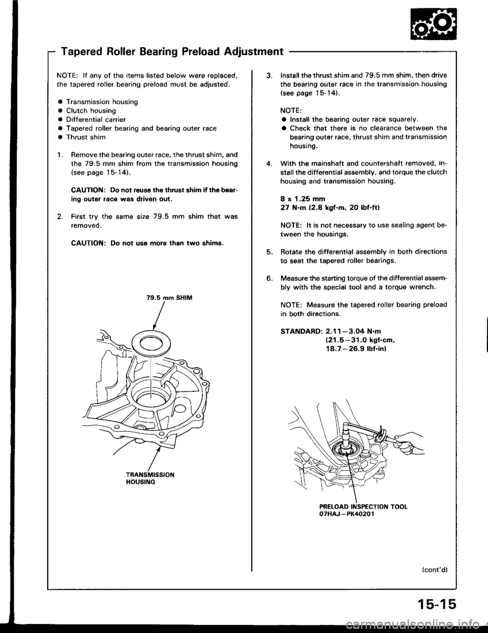
Tapered Roller Bearing Preload Adjustment
NOTE: lf any of the items listed below were replaced,
the tapered roller bearing preload must be adjusted,
a Transmission housing
a Clutch housing
a Diffe.ential carrier
a Tapered roller bearing and bea,ing outer race
a Thrust shim
1 . Remove the bearing outer race, the thrust shim, and
the 79.5 mm shim from the transmission housing
(see page 1 5- 14).
CAUTION: Do not reuss lhe thrust shim it the bear-
ing outer raco was driven out.
2. First t.y the same size 79.5 mm shim that was
removeo.
CAUTION; Do not uso moro than two shims.
79.5 rnm SHIM
HOUSING
4.
o.
Instsllthe thrust shim and 79.5 mm shim, then drive
the bearing outer race in the transmission housing
{see page l5-14).
NOTE:
a Install the bearing outer race squarely.
a Check that there is no clearance between the
bearing outer race. thrust shim and transmission
housing.
With the mainshaft and countershaft.emoved, in-
stsllthe differential assembly, and lorque the clutch
housing and transmission housing,
8 x 1.25 mm
27 N.m 12.8 kgf.m, 20 lbf.ft)
NOTE: lt is not necessary to use sealing agent be-
tween the housings.
Rotate the ditterential assembly in both directions
to seat the tapered roller bearings.
Measure the starting torque of the differenlial assem-
bly with the special tool and a torque wrench.
NOTE: Measure the tapered roller bearing preload
in both directions.
STANDARD: 2.1 1 -3.O4 N.m(21.5-31.0 kgf'cm,
18.7-26.9 lbf.inl
{cont'd}
15-15
Page 589 of 1413
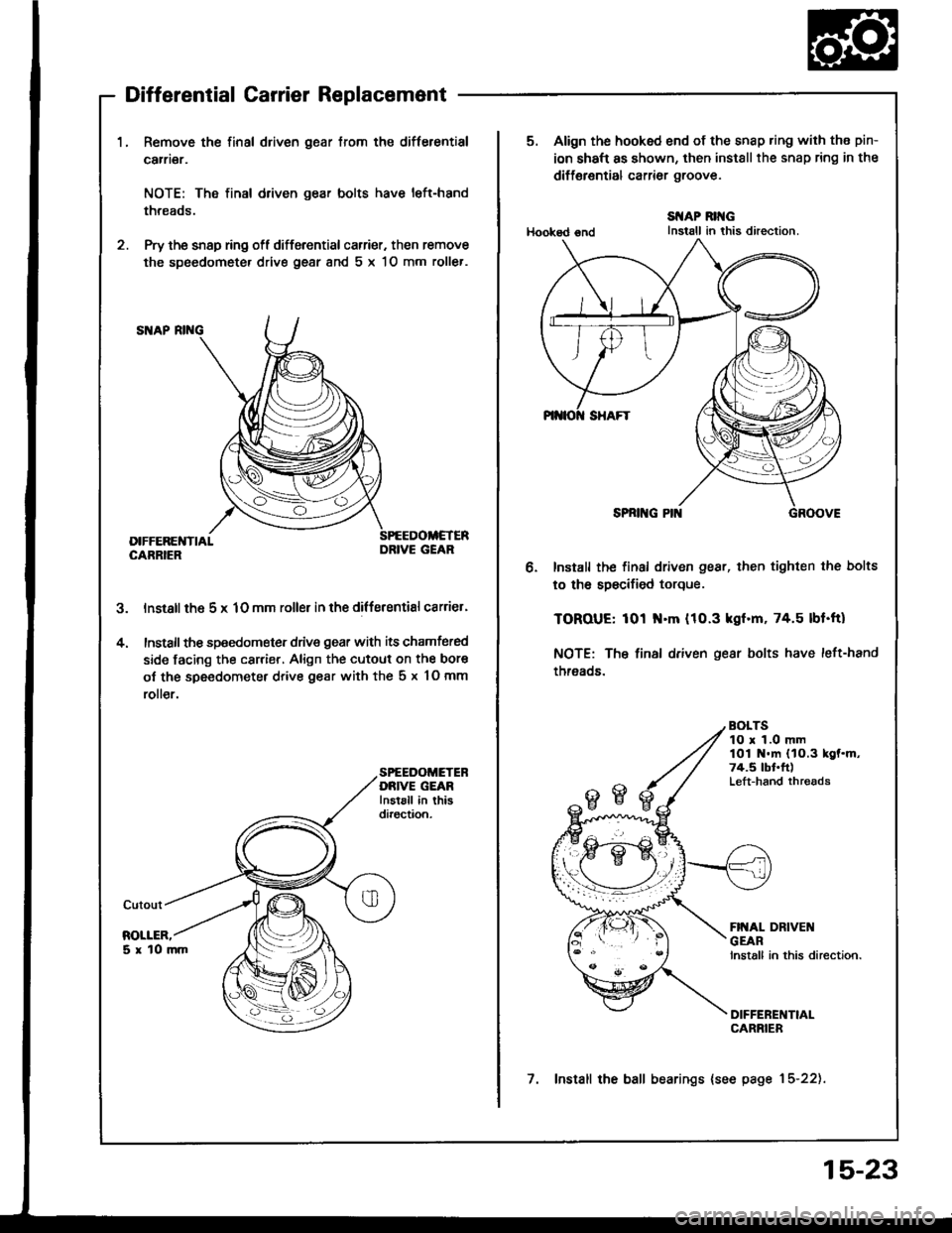
Differential Carrier Replacement
1.Remove the final driven gear from the differential
carrier.
NOTE: Tho final driven gear bolts have left-hand
threads.
Pry the snsp ring ofl differential carrier. then remove
the speedometer drive gear 8nd 5 x 1O mm roller.
lnstall th6 5 x 1O mm roller in the differentisl csrrier'
Install the speedom€ter drive gear with its chamfered
side facing the carrier, Align the cutout on the bore
of the speedometer drive gesr with the 5 x 10 mm
roll€r.
5.
4.
SPEEDOMETEBDRIVE GEARInstsll in thisdiroction.
DRIVE GEAR
5. Align the hooked end of the snap ring with the pin-
ion shaft as shown, then installthe snap ring in the
diff€rential carrior groove.
Hooksd €nd
SI{AP RII{GInstall in this direction.
o.Install the final driven gear, then tighten the bolts
to th6 spscified torque.
TOROUE: 101 N.m (10.3 kgf.m, 74.5 lbf.ft)
NOTE: The final driven gear bolts have left-hand
threads.
BOLTS10 r 1.0 mmlOi N.m (1O.3 kgf.m,74.5 tbt'ft)Left-hand thrgads
7. Install the ball bearings {see page 15-22).
15-23
Page 590 of 1413
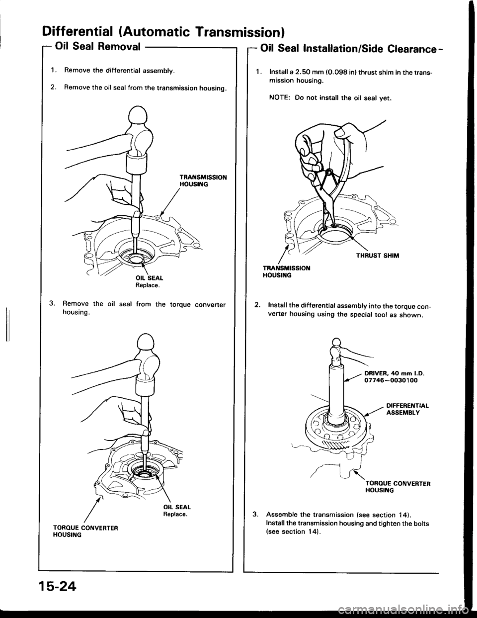
Differential (Automatic Transmissionl
Oil Seal Removal
Remove the differential assembly.
Remove the oil seal from the transmission housino.
TRAt{SMtSStONHOUSING
1.
2.
Oil Seal Installation/Side Clearance-
1. lnstalla 2.50 mm (O.O98 in) thrust shim in the rrans-
mission housing.
NOTE: Do not install the oil seal yet.
TRANSMISSIOHOUSING
Install the differential assembly into the torque con_v€ner housing using the special tool as shown.
DRIVER, 40 mm l.D.07746-OO30100
DIFFERENTIALASSEMBLY
/-l
TOROUE CONVERTERHOUSING
Assemble the transmission (see section 14).
Installthe transmission housing and tighten the bolts(see section 14).
OIL SEALReplace.
seal from therorque convener
TOROUE CONVERTERHOUSING
15-24
Page 591 of 1413
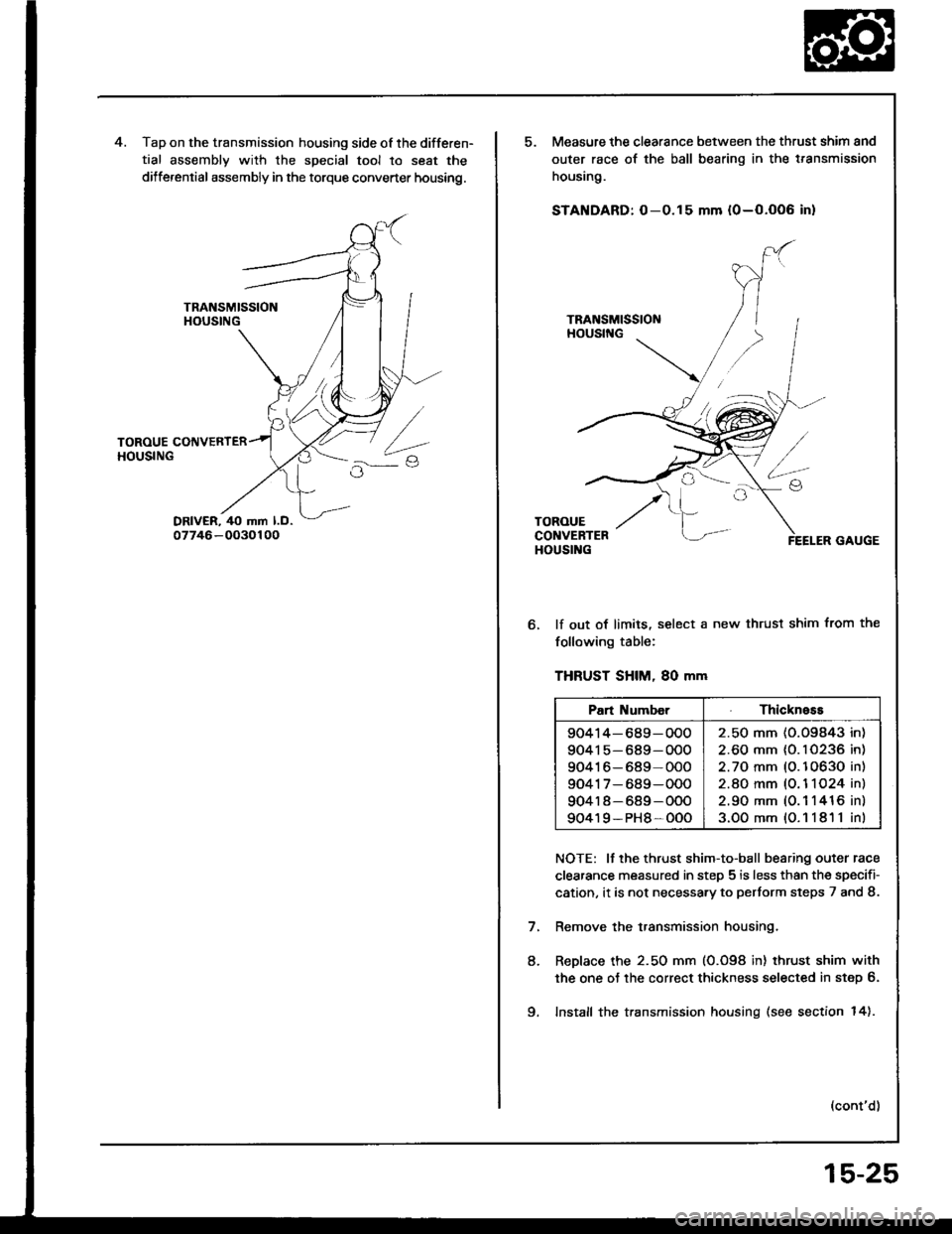
Tap on the transmission housing side of the differen-
tial assembly with the special tool to seat the
dilferential assembly in the torque converter housing.
Measure the clearance between the thrust shim and
outer race of the ball bearing in the t.ansmission
housing.
STANDARD: O-0.15 mm {0-O.OO6 in}
lf out of limits, select a new thrust shim from the
following table:
THFUST SHIM, 80 mm
NOTE: It the thrust shim-to-ball bearing outer race
clearance measured in step 5 is less than the specifi-
cation, it is not necessa.y to pertorm steps 7 and 8.
Remove the transmission housing.
ReDlace the 2.50 mm (0.098 in) thrust shim with
the one oJ the correct thickness selected in step 6.
Install the transmission housing (see section 14).
(cont'd)
8.
Pan Numb€rThickness
90414-689-OOO
90415-689-OOO
90416-689-000
9041 7- 689-000
904r 8-689-OOO
90419-PH8-OOO
2.50 mm (O.O9843 in)
2.60 mm {0. I 0236 in)
2.70 mm (O.10630 in)
2.8O mm (O. 1 1O24 in)
2.90 mm (0.1 1416 in)
3.OOmm{O.11811in)
9.
15-25
Page 592 of 1413
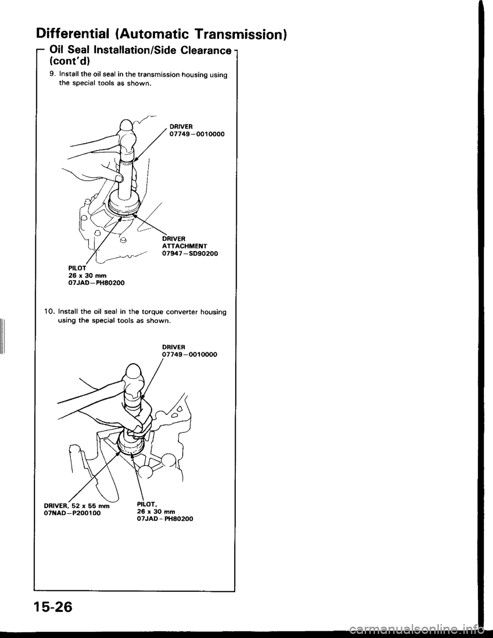
Differential (Automatic Transmissionl
Oil Seal Installation/Side Clearance
(cont'dl
9. Installthe oil seal in the transmission housing usingthe special tools as shown.
DRIVER07749-0010000
ATTACHMENT07947 -SD90200
26x30mmoTJAD-PH80200
10. Install the oil seal in the torque converter housing
using the special tools as shown.
DFIVER07749-0010000
DRIVER, 52 x 55 mmoTNAD-P200100
PILOT
15-26
Page 618 of 1413
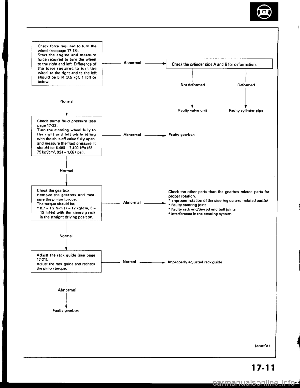
Ch6ck force r6quired to turn thowheel(see page 17-18).St6 the engine and m6asureforce required to turn the whgelto the right and left. Dilference olthe lo.ce required to turn thewho€l to the right and to the lettshould be 5 N (0.5 kgf, 1 lbf) orbelow.
Normal
Ch6ck pump fluid pressure (seepage 17-221.Turn the steering wheel lully tothe right and left whil€ idlingwith the shut-off valvo fully op6n,and measure tho fluid pressu.e. ltshould be 6,400 - 7,400 kPa (65 -
75 kg?cm,, 924 - 1,067 psil.
Normal
Abnormal -----|. Faulty gearbox
Abnormal |r
Chsck the other parts than the gearbox-ralated psrts forpropor rotstion,* lmpropor rotation ofthe steering column-rolat€d pan(sl'Faulty st6€ring jointa Faulty rack end^ie-rod end balljoints'Intederence in the steering system
lmproperly adjusted rack guide
(cont'dl
Chock the gearbox.Remove the goarbox and mea-sure the pinion torque.The torque should be;* 0.7 - 1.2 N.m (7 - 12 kgf.cm, 6 -'10 lbt in) with the steering rackin the straight driving position.
Normal
Adjust the rack guide (see page11-211.Adiust the rack guide and recheckthe pinion torque.
17-11
Page 639 of 1413
Steering Column
Installation (cont'dl
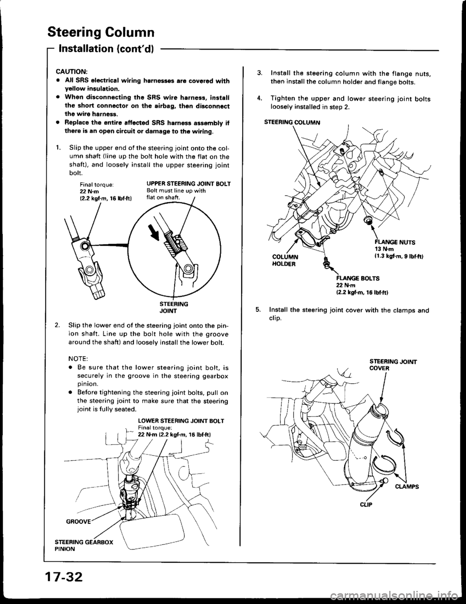
Finaltorque:22 N.m{2.2 kgf.m, 16lbt.ftl
CAUTION:
. All SRS electrical wiring hrrnossos are covgrod wilhyellow insulation,
. When disconn€cting the SRS wire harness, installthe short connector on the airbag. th€n dbconnoct
the wire harness.
. Replaca the entire alfected SRS harness assembly if
there is an open circuit or damage to tho wiring.
1. Slip the upper end of the steering joint onto the col-
umn shaft {line up the bolt hole with the flat on the
shaft), and loosely install the upper steering joint
bolt.
UPPER STEERING JOINT BOLTBolt must line up withflat on shaft.
STEERINGJOINT
Slip the lower end of the steering joint onto the pin-
ion shaft. Line up the bolt hole with the groove
around the shaft) and loosely jnstallthe lower bolt.
NOTE:
. Be sure that the lower steering joint bolt. is
securely in the groove in the steering gearbox
pinion.
. Before tightening the steering joint bolts, pull on
the sleering joint to make sure that the steeringjoint is fully seated.
LOWER STEERING JOINT BOLTFin6ltoroue:22 N.m {2.2 kgt m. 15 lbf.ftl
17 -32
Install the steering column with the flange nuts,then installthe column holder and flange bolts.
Tighten the upper and lower steering joint boltsloosely installed in steD 2,
FLANGE BOLTS22 N.m12.2 ksi.m, 16 tbtftl
Install the steering joint cover with the clamps andclip.
CLIP