Strut ACURA INTEGRA 1994 Service Repair Manual
[x] Cancel search | Manufacturer: ACURA, Model Year: 1994, Model line: INTEGRA, Model: ACURA INTEGRA 1994Pages: 1413, PDF Size: 37.94 MB
Page 48 of 1413
Engine Removal/lnstallation
@a Make sure jacks and safety stands aro placed ploper-
ly and hoisl brackots arg attachod to the correct po-
sitions on tho engine (se€ ssction 1).
a Mak€ sure tho car willnot roll off stands and tallwhile
you are wotking under it'
CAUTION:
a Use fendet covals to avoid damaging painted
sudaces.
r Unspecified itsms alo common
a Unplug tho widng connectots carefully while holding
the couplor and tha connector portion to avoid
oamage.
a Mark all wiring and hoses to avoid misconnection.
Also, be sulo that thsy do not contact other wiring
or hoses, or interfere with oth€l parts.
NOTE: Anti-theft radios have a coded theft ptotection
circuit. Be sure to get the customer's code number beJore
- Disconnecting the batterY.
- Removing the No. 32 (7.5 A) fuse from the under-
hood tuse/relay box.- Removing the radio
Atter service, reconnect power to the radio and turn it
on. When the word "CODE" is displayed, enter the cus-
tomer's 5-digit code to restore radio operataon.
1. Remove the hood (see section 2O).
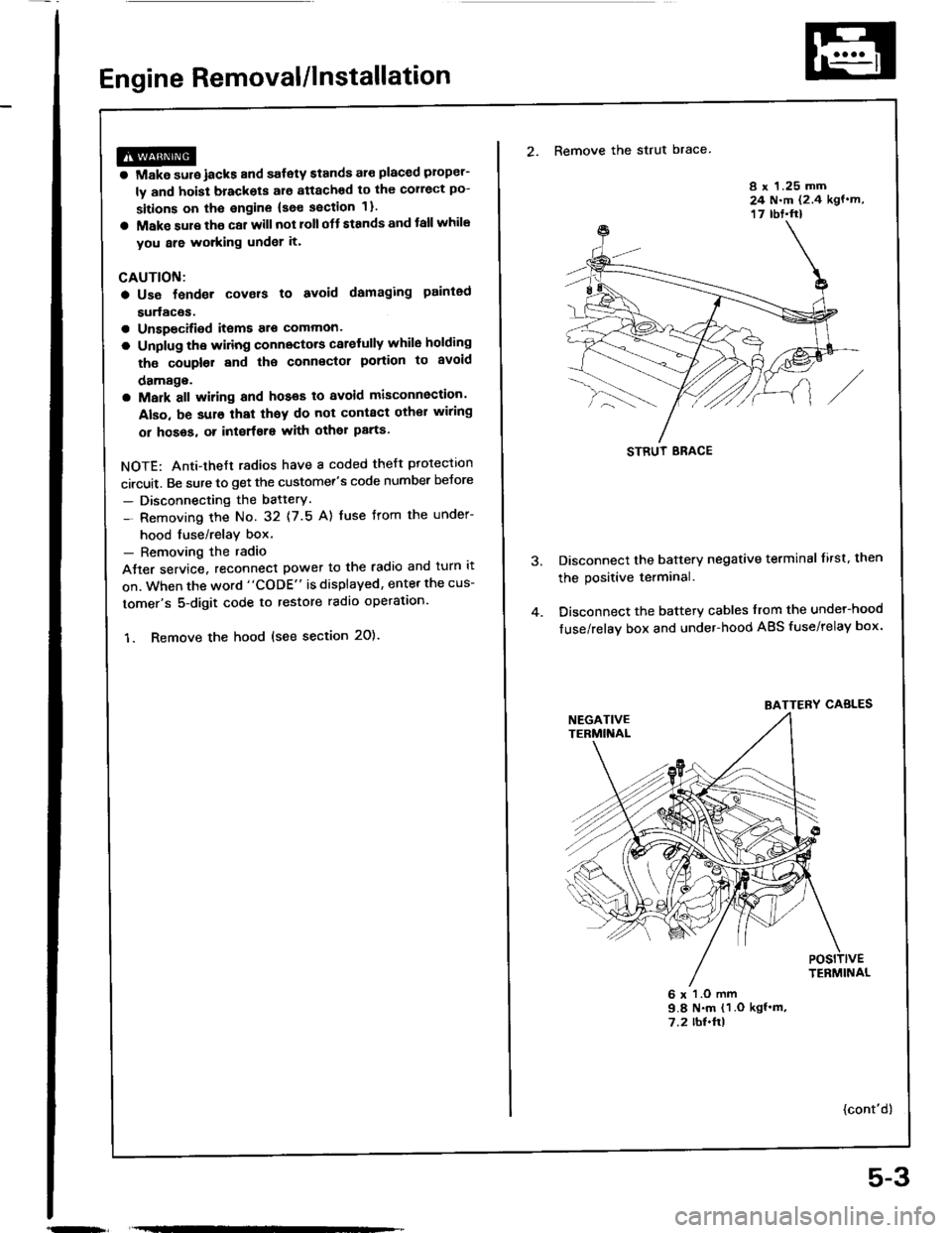
2. Remove the strut brace
8 x 1.25 mm24 N.m (2.4 kgf.m,17 rbt.ft)
Disconnect the battery negative terminal lirst. then
the positive terminal.
Disconnect the battery cables from the undel-hood
fuse/relay box and under-hood ABS fuse/relay box.
6 x l.O mm9.8 N.m (1 .O kgf'm,7.2 rbl.ftl
{cont'd)
STRUT ERACE
BATTERY CABLES
5-3
Page 116 of 1413
Cylinder Head
Removal
Engine removal is not required or this procedure.
CAUTION: To avoid damaging tho cylinder head, wail
u[tilths.nginc coolant tsmperaturo drops bolow 100"F(38'Cl bafore loos6ning tho retaining bolts.
NOTE;
. Inspect the timing belt before removing the cylinder
head.
Turn the crankshaft pulley so that the No. 1 piston is
at top dead center (TDc) {page 6-51).
Mark all emissions hoses betore disconnecting them.
Anti-theft radios have a coded theft protection circuit.
Be sure to get the customer's code number before- Disconnecting the battery.- Removing the No.32 (7.5 A) fuse trom the under-
hood fuse/relay box.- Removing the radio.
After service, reconnect power to the radio 8nd turn it
on.
When the word "CODE" is displaved. enter the cus-
tomer's 5-digit code to restore radio operation,
Disconnect the negative terminal from the battery.
Drain the engine coolant (see page 10-5).
. Remove the radiator cap to speed draining.
Relieve fuel pressure (see section 111.
l@ Do not 3moke whilo working on fuel
a
a
'1.
systgm. ko6p opon tlamo ot Spark away trom work
aroa. Drain fugl only into an approved containsr,
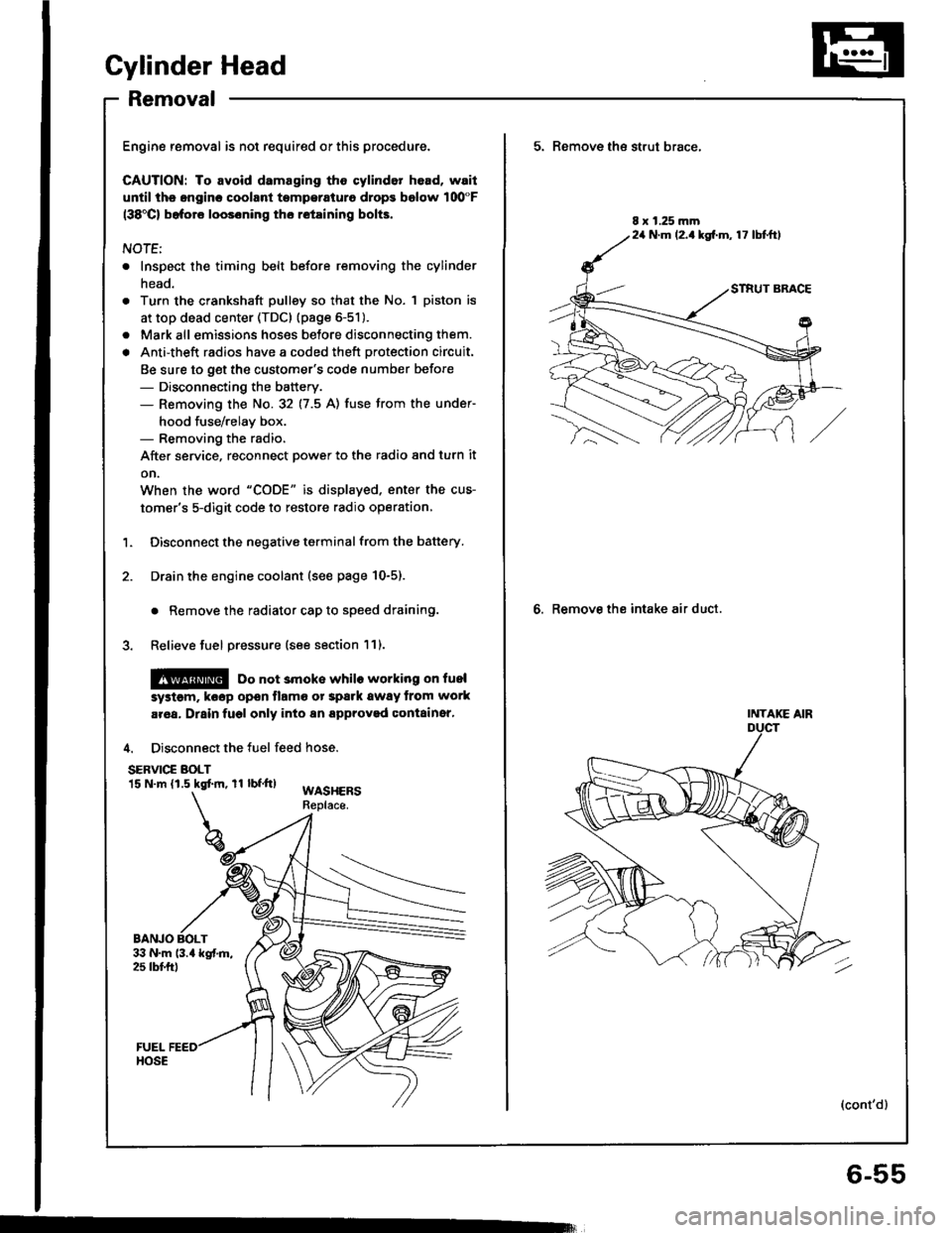
4. Disconnect the fuel feed hose.
SERVIC€ BOLT15 N.m (1.5 kgtm, rl bf.tt)WASHERSReplace.
BANJO BOLT
5. Remove th€ strut brace,
6. Remove the intake air duct.
8 x 1.25 mm24 N.m (2.1kg[.m, 17 lbtftl
INTAKE AIR
(cont'd)
6-55
Page 1016 of 1413
8.
o.
7.
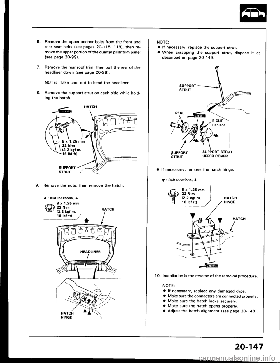
9. Remove the nuts, then remove the hatch.
a : Nut locations, 4
Remove the uDDer anchor bolts from the tront and
rear seat belts {see pages 20-1 1 5, 'l 19), then re-
move the upper portion of the quarter pillar trim panel
(see page 20-991.
Remove the rear roof trim, then pull the rear of the
headliner down (see page 2O-99).
NOTE: Take care not to bend the headliner,
Remove the support stfut on each side while hold-
ing the hatch.
SUPPORTSTRUT
HATCH
HATCH
I x 1.25 mm22Nm
12,2 kgt'm,16 tbt.ftl
12.2 kgl.m, I,6'y!:t ,/
NOTE:
a lf necessary, replace the support strut.a When scrapping the suppon $rut, dispose ir as
described on page 20-149.
a lf necessary, remove the hatch hinge.
V : Solt locdlions, 4
8 x 1.25 mm22 N.rn12.2 kgt.m,16 tbf.ft)HATCHHINGE
HATCH
1O. Installation is the reverse ot the removal procedure.
NOTE:
a lf necessary, replace any damaged clips.a Make sure the connectors are connected properly.
a Make sure the hatch locks securely.a Make sure the hatch opens properly.
a Adjust the hatch alignment (see page 20-148).
20-147
Page 1017 of 1413
Hatch
Adjustment
NOTE:
a Before ad,usting the hatch. loosen each bolt and nut slightly.
a Do not install the suDDort struts.
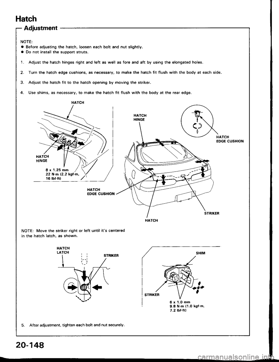
1.Adjust the hatch hinges right and left as well as fore and aft by using the elongated holes.
Turn the hatch edge cushions, as necessary. to make the hatch tit flush with the body at each side.
Adjust the hatch fit to the hatch opening by moving the striker,
Use shims, as necessary, to make the hatch tit flush with the body at the rear edge.4.
HATCHEDGE CUSHION
NOTE: Move the striker right or left until it's centered
in the hatch latch, as shown.
HATCHLATCH
t+Q.
6x1.0mm9.8 N m (1.0 kgl m,7 .2 tbt.trl
HATCH
8 x 1.25 mm
HATCH
5. Atter adjustment, tighten each bolt and nut securely,
Page 1018 of 1413
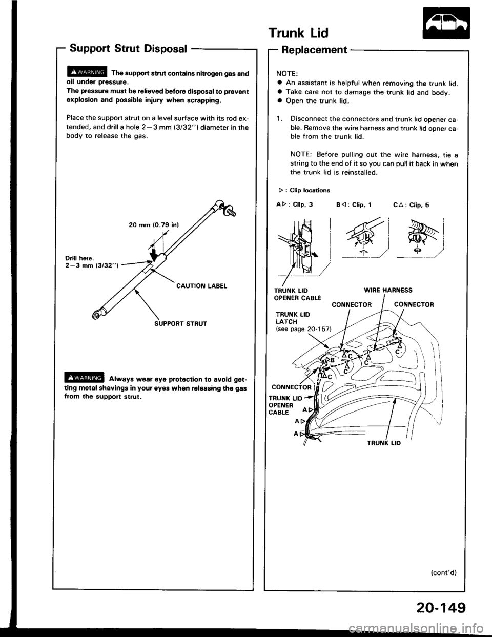
20 mm (O.79 inl
SUPPORT STRUT
Support Strut Disposal
@ Tha support strut contains nitrog.n gas andoil unde. pr€ssul€.
The pressure must be relieved bsfo.e disposal to prevant
explosion and possible injury wh€n sc.apping.
Place the support strut on a level surface with its rod ex-
tended, and drilla hole 2-3 mm (3/32"1diameter in the
body to release the gas.
@ always w€ar €ye prot6ction to avoid get-
ting motal shavings in your eyea when roloasing th€ gas
fiom the support st.ut.
Trunk Lid
TRUNK LIDOPEN€R CABLE
TRUNK LIDLATCH{see page 20-157}
TRUNK LIOOPENERCABLE
CA : Clip, 5
e-i
_rP ,/
Replacement
NOTE:
a An assistant is helpful when removing the trunk lid.a Take care not to damage the t.unk lid and body.a Open the trunk lid.
1. Disconnect the connectors and trunk lid opener ca-ble. Remove the wire harness and t.unk lid opner ca-ble from the trunk lid.
NOTE: Before pulling out the wire harness, tie astring to the end ot it so you can pull it back in when
the trunk lid is reinstalled.
> : Clip locationg
AD : Clip, 3 B< : Clip, 1
WIRE HARNESS
CONNECTORCONIIECTOR
A
A
(cont'd)
20-149