fuse box ACURA INTEGRA 1994 Service Repair Manual
[x] Cancel search | Manufacturer: ACURA, Model Year: 1994, Model line: INTEGRA, Model: ACURA INTEGRA 1994Pages: 1413, PDF Size: 37.94 MB
Page 4 of 1413
,,
SUPPLEMENTAL RESTRAINT SYSTEM (SRS}
The Integra SRS includes a driver's airbag, located in the steering wheel hub. ln addition, all mod€ls excepi tna
Rs model for canada have a front passenger's airbsg located in the dashboard above the glove box, InformaUon
necessary to safely service the SRS is included in this servica Manual. ltems marked with an sstorisk (r) on thr
contents page include, or are located near, SRS components. Servicing. disassembling or roplacing thea6 ltems
will require special precautions and tools, and should thoreiore be done by an authorhed Acura dealer.
' To avoid rondering ths sRS inoporativo, which could lard to porronll Injury or darth In thc cvant ot. r.yr.
trontal collision, all sRs sorvico work must be pcrformcd by !n ruthorizcd Acu.! daerrr,
' lmpTopor 3orvica proceduroa, including inco.roct r.movd r d Installation of tha SRS, could Lld to pc[onc Inlu-
ry caussd by unintsntional activation ot tho airbags.
' All sRs oloctrical wiring harnoa$! aro coverod with yallow In3ulatlon, Rcbtcd componcnts arc bcrtad In tha
stoering Golumn, front console, dsrhboa.d, and darhboard lowor plnol, lnd in thc d$hbolrd abovc tha gaov!
bor. Do not uas oloctdcal te$ oquipmont on thaaa citcuhs.
NoTE: The original radio has a coded thett protection circuit. Be sure to get the customer's code numb6r b€lore* disconnecting the battery.
- removing the No. 32 (7.S A) fuse Jrom the undsr-hood fuse/relay box.
- removing the radio.
After service, reconnect power to the radio and turn it on. When the word ,,CODE,, is displayed, enter the cus_
tomer's 5-digit code to restore radio oDerauon.
Page 36 of 1413
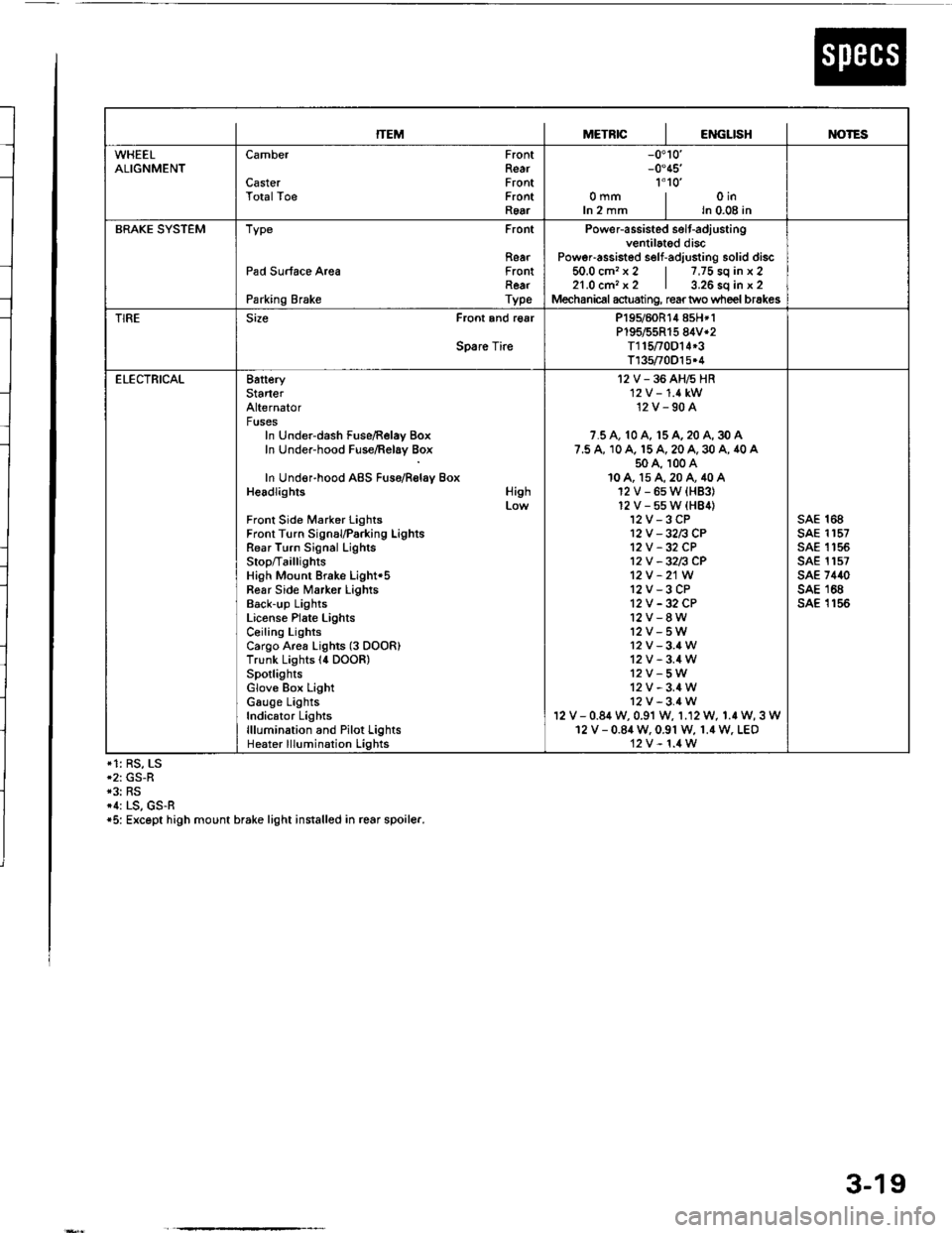
ITEMMETRICIENGLISHIM)TES
WHEELALIGNMENTCamber
CasterTotalToe
FrontRearFrontFrontRear
-0.10'-0.45'�
1'1o'�omm | oinIn 2 mm I ln 0.08 in
BRAKE SYSTEMType Front
RearPad Surface Area FrontRearParking Brake Type
Power-assisted selt-adiustingventilated discPoweFassisted self-adjusting solid discio.u cm. x z | /,/5 so tn x z21.0 cm, x2 | 3.26 sq in x 2Mechanical actuating, rear two wheel brakes
TIRESize Front and r€ar
Spare Tire
P195/60R14 858*1P195/55R15 84V*2T115t0D14*3T135/70O15.4
ELECTRICAL8atteryStarterAlternatorFusesIn Under-dash Fuse/Relay BoxIn Under-hood Fuse/Relay Box
In Under-hood ABS Fuso/Rolay BoxHeadlights
Front Side Marker LightsFront Turn SignauParking LightsRear Turn Signal LighlsStop/Ta illig htsHigh Mount Brake Light'5Fear Side Marker LightsBack-up LightsLiconse Plate LightsCeiling LightsCargo Area Lights (3 DOOR)Trunk Lights l4 DOOR)SpotlightsGlove Box LightGauge LightsIndicator Lightslllumination and Pilot LightsHeater lllumination Lights
High
I2V-36AH6HR'12 V -'1.4 kW12V-90A
7.5 A, 10 A, 15 A, 20 A, 30 A7.5 A, 10 A. 15 A, 20 A, 30 A, 40 A50 A, 100 A10A, 15A,20A,40A12V-6sW{HB3}12V-55W(HB4)12V-3CP12V -32n CP12V -32 CP12V -32n CP12V -21W
12V-3CP12V -32 CP12V-8W12V-5W12v-3.4W12V-3.4W12V-5W12V-3.4W12V-3.4Wv - 0.84 w, 0.91 w, 1.12 W, 1.r W, 3 W12 V - 0.84 W. 0.91 W, 1.4 W. LEO12V-1.4W
sAE 168sAE 1157sAE 1 '�t 55sAE 1157sAE 7440sAE 168sA€ 1156
*1: RS, LS*2: GS-R*3: RS*1: LS, GS-R*5: Except high mount brake light installed in rcar spoiler.
3-19
Page 48 of 1413
Engine Removal/lnstallation
@a Make sure jacks and safety stands aro placed ploper-
ly and hoisl brackots arg attachod to the correct po-
sitions on tho engine (se€ ssction 1).
a Mak€ sure tho car willnot roll off stands and tallwhile
you are wotking under it'
CAUTION:
a Use fendet covals to avoid damaging painted
sudaces.
r Unspecified itsms alo common
a Unplug tho widng connectots carefully while holding
the couplor and tha connector portion to avoid
oamage.
a Mark all wiring and hoses to avoid misconnection.
Also, be sulo that thsy do not contact other wiring
or hoses, or interfere with oth€l parts.
NOTE: Anti-theft radios have a coded theft ptotection
circuit. Be sure to get the customer's code number beJore
- Disconnecting the batterY.
- Removing the No. 32 (7.5 A) fuse from the under-
hood tuse/relay box.- Removing the radio
Atter service, reconnect power to the radio and turn it
on. When the word "CODE" is displayed, enter the cus-
tomer's 5-digit code to restore radio operataon.
1. Remove the hood (see section 2O).
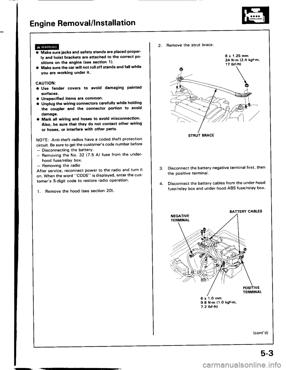
2. Remove the strut brace
8 x 1.25 mm24 N.m (2.4 kgf.m,17 rbt.ft)
Disconnect the battery negative terminal lirst. then
the positive terminal.
Disconnect the battery cables from the undel-hood
fuse/relay box and under-hood ABS fuse/relay box.
6 x l.O mm9.8 N.m (1 .O kgf'm,7.2 rbl.ftl
{cont'd)
STRUT ERACE
BATTERY CABLES
5-3
Page 78 of 1413
Gylinder Head
Removal
I
t
Engine removal is not required for this procedure.
CAUTION: To avoid damaging tho cylinder head, wait
until tho ongino coolant temporature drops bolow 100"F
{38"C) beforo loo36ning the rotainin0 bolts.
NOTE:
. Inspect the timing belt before removing the cylinder
neao.
. Turn the crankshaft pulley so that the No. 1 piston is
at top dead center (TDCI (page 6-12).
. Mark all emissions hoses before disconnecting them.. Anti-theft radios have a coded theft protection circuit.
Be sure to get the customer's code number before.- Disconnecting the battery.- Removing the No. 32 (7.5 A) fuse irom the under-
hood fuse/relay box.- Removing the radio.
After service, reconnect oower to the radio and turn it
on.
When the word "CODE" is displayed, enter the cus-
tomer's 5-digit code to restore radio operation.
1. Disconnect the negative terminalfrom the battery.
2. Drain the engine coolant (see page 10-5).
. Remove the radiator cap to speed draining.
3. Relieve fuel pressure (see Section 1 1).
@ Do not smoke whils working on tusl
systom, keep opon flame or spark away trom work
area. Drain fuol only inlo an approvod containsr.
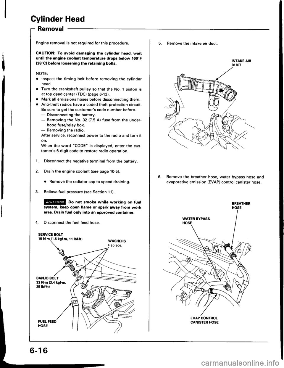
4. Disconnect the fuel feed hose.
SERVIC€ BOLT
WASHERSReplace.
5, Remove the intake air duct.
Remove the breather
evaporative emission
hose, water bypass hose and(EVAP) control canister hose.
Page 116 of 1413
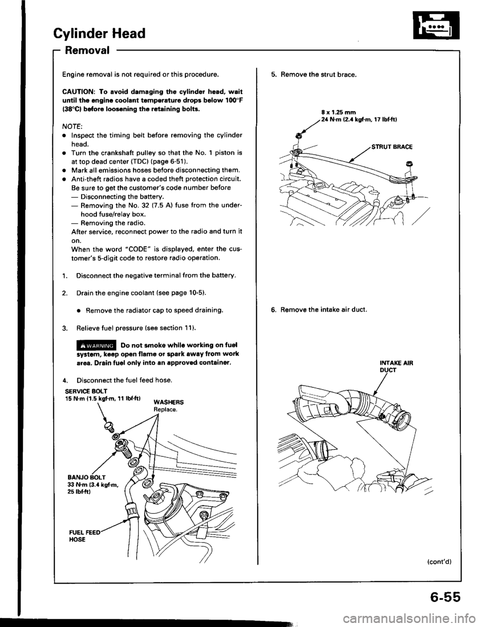
Cylinder Head
Removal
Engine removal is not required or this procedure.
CAUTION: To avoid damaging tho cylinder head, wail
u[tilths.nginc coolant tsmperaturo drops bolow 100"F(38'Cl bafore loos6ning tho retaining bolts.
NOTE;
. Inspect the timing belt before removing the cylinder
head.
Turn the crankshaft pulley so that the No. 1 piston is
at top dead center (TDc) {page 6-51).
Mark all emissions hoses betore disconnecting them.
Anti-theft radios have a coded theft protection circuit.
Be sure to get the customer's code number before- Disconnecting the battery.- Removing the No.32 (7.5 A) fuse trom the under-
hood fuse/relay box.- Removing the radio.
After service, reconnect power to the radio 8nd turn it
on.
When the word "CODE" is displaved. enter the cus-
tomer's 5-digit code to restore radio operation,
Disconnect the negative terminal from the battery.
Drain the engine coolant (see page 10-5).
. Remove the radiator cap to speed draining.
Relieve fuel pressure (see section 111.
l@ Do not 3moke whilo working on fuel
a
a
'1.
systgm. ko6p opon tlamo ot Spark away trom work
aroa. Drain fugl only into an approved containsr,
4. Disconnect the fuel feed hose.
SERVIC€ BOLT15 N.m (1.5 kgtm, rl bf.tt)WASHERSReplace.
BANJO BOLT
5. Remove th€ strut brace,
6. Remove the intake air duct.
8 x 1.25 mm24 N.m (2.1kg[.m, 17 lbtftl
INTAKE AIR
(cont'd)
6-55
Page 204 of 1413
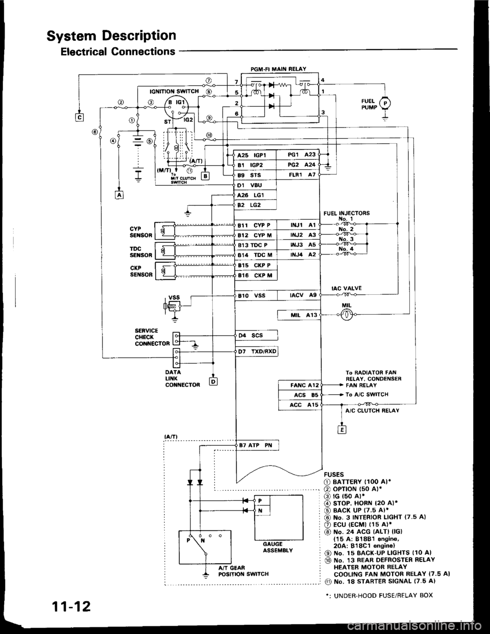
System Description
Electrical Connections
PGM.FI MAII{ RELAY
- rc2l L
IllLii |
ril.i--r {a/Tl
To BAOIATOR FAt!RETAY, CONDENSERFAI{ RELAY
To A/C SWITCH
FUEL INJ€CTORS
@
DATALIIIKco t{EcToR
fUELPUMP
A/C CLUTCH RELAY
FUSES
O BATTERY I1OO AI*
@ oPTroN t50 alr
o rG {50 A).
@ sroP. HoBN {2O Al*
@ BACK UP (7.5 Al*
@ No. 3 INTERIOR LIGHT {7.5 A)
O Ecu (EcMt (1s A)'
@) No. 24 ACG (ALTI 0Gl{15 A: 81881 sngin6,2OA:818C1 6n9ine)
@ No. 15 BAcK-uP LlcHTs llo Al
@ No. 13 REAR DEFROSTER RELAYHEATER MOTOR RELAYCOOLING FAN MOTOR RELAY I7.5 A}
O No. l8 STARTER SIGNAL 17.5 A)
*: UNDER-HOOD FUSE/RELAY BOX
11-12
A/T GEAR
Page 216 of 1413
![ACURA INTEGRA 1994 Service Repair Manual System Description
System Connectors [Dash and Floor]
PGM-FI MAINRELAY
C1I44 UNDEN-OASHFUSE/REALYBOX
ENGINECOMPARTMENTWIRE
DASHBOARO WIREHARNESS
MAINWIREHARI{ESS
REARWIREHARNESS
11-24 ACURA INTEGRA 1994 Service Repair Manual System Description
System Connectors [Dash and Floor]
PGM-FI MAINRELAY
C1I44 UNDEN-OASHFUSE/REALYBOX
ENGINECOMPARTMENTWIRE
DASHBOARO WIREHARNESS
MAINWIREHARI{ESS
REARWIREHARNESS
11-24](/img/32/56982/w960_56982-215.png)
System Description
System Connectors [Dash and Floor]
PGM-FI MAINRELAY
C1I44 UNDEN-OASHFUSE/REALYBOX
ENGINECOMPARTMENTWIRE
DASHBOARO WIREHARNESS
MAINWIREHARI{ESS
REARWIREHARNESS
11-24
Page 218 of 1413
![ACURA INTEGRA 1994 Service Repair Manual System Description
System Connectors [Dash and Floor] {contd}
UNDER-DASHFUSE/RELAYBOX
DASHBOARDHARNESS
MAINWIREHARNESS
11-26 ACURA INTEGRA 1994 Service Repair Manual System Description
System Connectors [Dash and Floor] {contd}
UNDER-DASHFUSE/RELAYBOX
DASHBOARDHARNESS
MAINWIREHARNESS
11-26](/img/32/56982/w960_56982-217.png)
System Description
System Connectors [Dash and Floor] {cont'd}
UNDER-DASHFUSE/RELAYBOX
DASHBOARDHARNESS
MAINWIREHARNESS
11-26
Page 227 of 1413
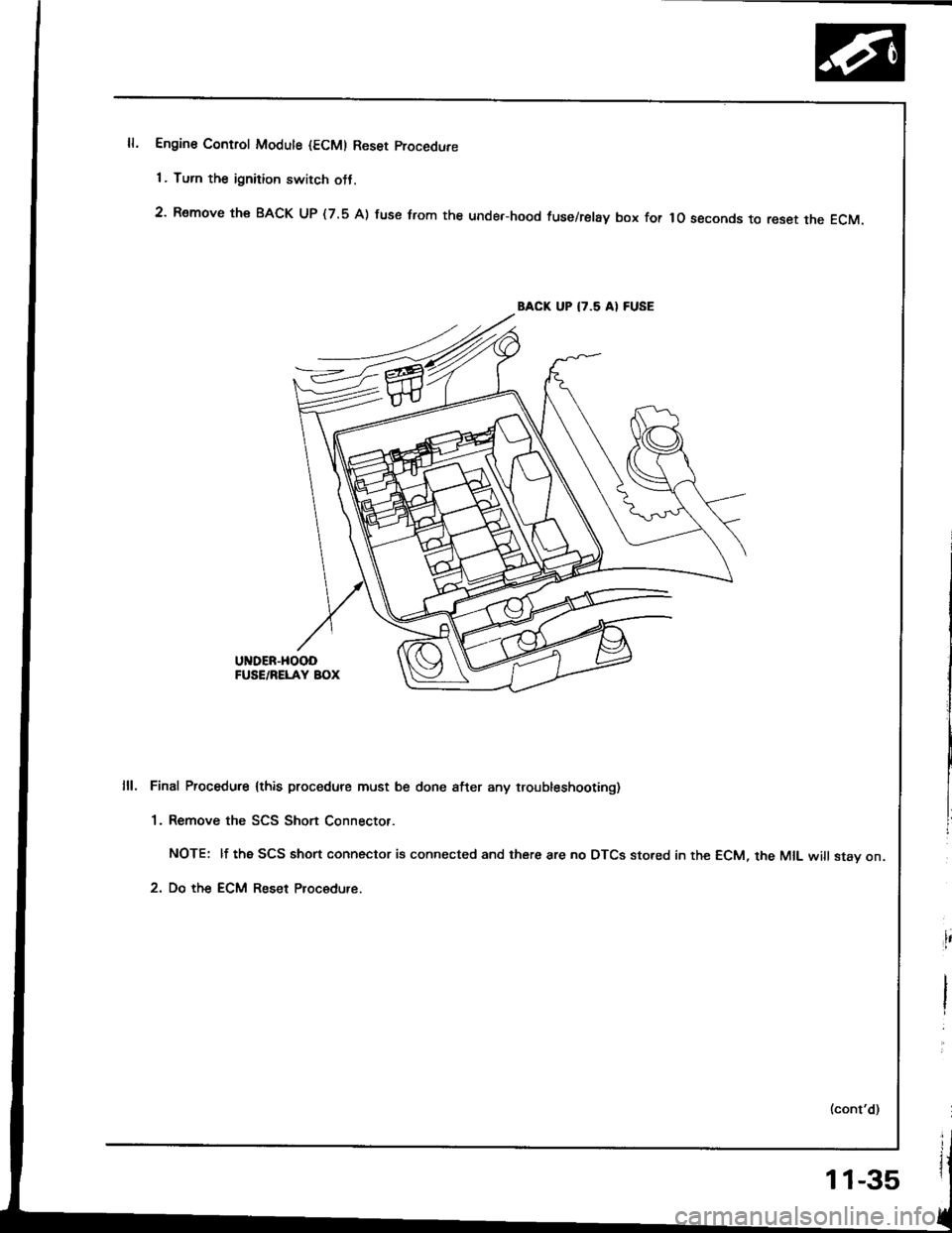
Engine Control Modute {ECM) Reset procedure
1 . Turn the ignition switch otJ.
2' Remove th€ BACK UP (7.5 A) fuse trom the unde.-hood fuse/relay box for lo seconds to reset the EcM.
BACK UP I7.5 AI FUSE
UNDER-HOOOFUSE/RELAY BOX
Final Procedure lthis procedure must be done after any troubleshooting)
1. Remove the SCS Short Connector.
NOTE: lf the SCS short connector is connected and there are no DTCS sto.ed in the ECM, the MIL will stav on.
2. Do the ECM Reset Procedure.
11-35
Page 234 of 1413
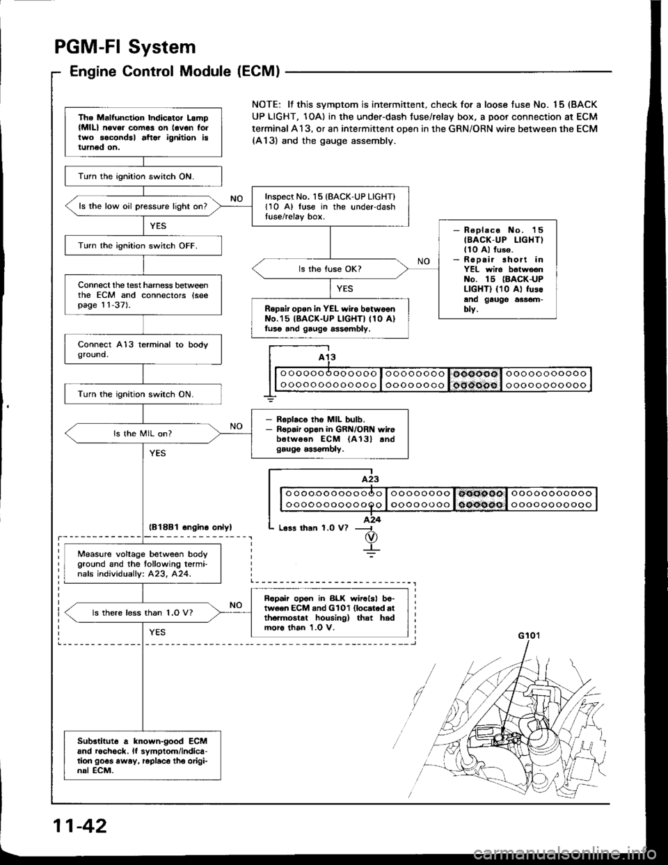
PGM-FI System
Engine Control Module (ECM)
lB18B1 ongino onlyl
The Malfunction Indicator Lamp(MlL) n6v6. com6s on lovon follwo socondal aftor ignition istumed on.
lurn the ignition switch ON.
Inspect No. 15 {BACK-UP LIGHT}l1O A) luse in the underdashtuse/relay box.ls the low oil pressure light on?
- R€placo No. 'l5
IBACK-UP LIGHT)llo Al fuso.- Ropair short inYEL wiro botwoonNo. 15 (BACK-UP
LIGHT) {10 A) fusoano gauge 6$om-blv.
Turn lhe ignition switch OFF.
ls the fuse OK?
Connecl the test harness betweenthe ECM and connectors (seepag€ 11-37).Repair opon in YEL wiio botw6onNo.'15 IBACK-UP LIGHTI 110 A)luso and gaug6 assombly.
Turn the ignition switch ON.
- RsDlaco tho MIL bulb.- Ropair opon in GRN/ORN wi.ebetwoen ECM {A13} andgaug€ a$6mbly.
ls the MIL on?
Measure voltage between body
Oround and the tollowing termi-nafs individuallv: 423, 424.
Ropah op6n in BLK wirolsl bo-tw6en ECM and GlOl llocatod atthormostat housing) that hadmoro than 1.0 V.
ls there less than 1.O V?
Substituto a known-good ECMand rochgck, lf symptom/indica-tion go€s away, roplaco tho origi-nal ECM.
NOTE: lf this svmptom is intermittent. check for a loose fuse No. 15 (BACK
UP LIGHT, 1OA) in the under-dash Juse/relay box, a poor connection at ECM
terminal A13, or an intermittent open in the GRN/ORN wire between the ECM(A13) and the gauge assembly.
I A13
I| | o oooo oooooooo I oooo oooo I ooooool ooooooooooo I
G 10'�l
11-42