turn signal ACURA INTEGRA 1994 Service Repair Manual
[x] Cancel search | Manufacturer: ACURA, Model Year: 1994, Model line: INTEGRA, Model: ACURA INTEGRA 1994Pages: 1413, PDF Size: 37.94 MB
Page 36 of 1413
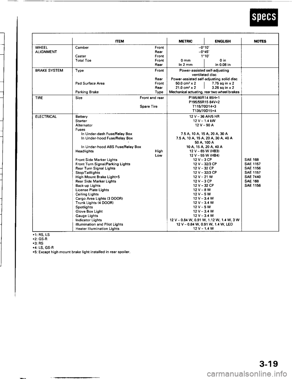
ITEMMETRICIENGLISHIM)TES
WHEELALIGNMENTCamber
CasterTotalToe
FrontRearFrontFrontRear
-0.10'-0.45'�
1'1o'�omm | oinIn 2 mm I ln 0.08 in
BRAKE SYSTEMType Front
RearPad Surface Area FrontRearParking Brake Type
Power-assisted selt-adiustingventilated discPoweFassisted self-adjusting solid discio.u cm. x z | /,/5 so tn x z21.0 cm, x2 | 3.26 sq in x 2Mechanical actuating, rear two wheel brakes
TIRESize Front and r€ar
Spare Tire
P195/60R14 858*1P195/55R15 84V*2T115t0D14*3T135/70O15.4
ELECTRICAL8atteryStarterAlternatorFusesIn Under-dash Fuse/Relay BoxIn Under-hood Fuse/Relay Box
In Under-hood ABS Fuso/Rolay BoxHeadlights
Front Side Marker LightsFront Turn SignauParking LightsRear Turn Signal LighlsStop/Ta illig htsHigh Mount Brake Light'5Fear Side Marker LightsBack-up LightsLiconse Plate LightsCeiling LightsCargo Area Lights (3 DOOR)Trunk Lights l4 DOOR)SpotlightsGlove Box LightGauge LightsIndicator Lightslllumination and Pilot LightsHeater lllumination Lights
High
I2V-36AH6HR'12 V -'1.4 kW12V-90A
7.5 A, 10 A, 15 A, 20 A, 30 A7.5 A, 10 A. 15 A, 20 A, 30 A, 40 A50 A, 100 A10A, 15A,20A,40A12V-6sW{HB3}12V-55W(HB4)12V-3CP12V -32n CP12V -32 CP12V -32n CP12V -21W
12V-3CP12V -32 CP12V-8W12V-5W12v-3.4W12V-3.4W12V-5W12V-3.4W12V-3.4Wv - 0.84 w, 0.91 w, 1.12 W, 1.r W, 3 W12 V - 0.84 W. 0.91 W, 1.4 W. LEO12V-1.4W
sAE 168sAE 1157sAE 1 '�t 55sAE 1157sAE 7440sAE 168sA€ 1156
*1: RS, LS*2: GS-R*3: RS*1: LS, GS-R*5: Except high mount brake light installed in rcar spoiler.
3-19
Page 224 of 1413
Troubleshooting
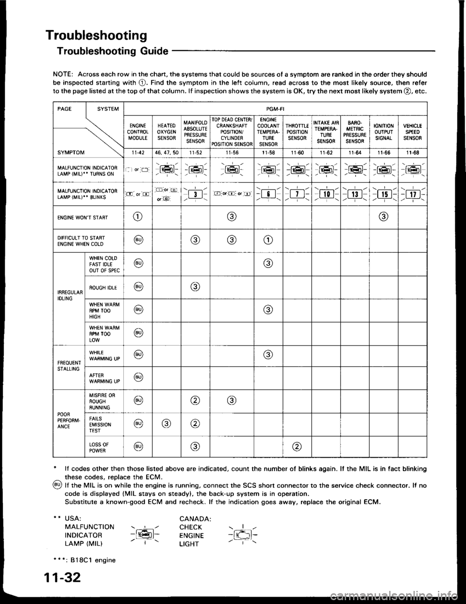
Troubleshooting Guide
NOTE: Across each row in the chart. the systems that could be sources of a symptom are ranked in the order they should
be inspected staning with O. Find the symptom in the left column, read across to the most likely source. then refer
to the page listed at the top of that column. lf inspection shows the system is OK, try the next mosr likely system O, etc,
* lf codes other then those listed above are indicated, count the number of blinks again. It the MIL is in fact blinking
^ these codes, replace the ECM.
qy, lf the MIL is on while the engine is running. connect the SCS shon connector to the service check connector. It no
code is displayed {MlL stays on steady), the back-up system is in operation.
Substitute a known-good ECM and recheck. lf the indication goes away, replace the original ECM.
USA:
MALFUNCTION
INDICATOR
LAMP {MIL)
CANADA: ----l CHECK-ltGl- ENGTNE- | - LTGHT
- { -1t-
* * *: 818C1 engine
1-32
SYMPTOM
PGM.FI
ENGINECONTROLMOOULE
HEATEOOXYGENSENSOR
MANIFOLOAESOLUTEPRESSURESENSOR
TOP DEAD CINTTR/CRANKSHAFTPOSTT|ON/CYLINDERPOSITION SENSOR
ENGINECOOLANTTEMPfRA.TURTSENSOR
THROTTTEPOStTtONSENSOR
INfAKE AIRTEMP€RA.TUREsar,rs0R
BARO.METRICPRESSURESENSOR
IGNITIONOUTPUTSIGNAL
vEHtct-ESPfEDSENSOR
11.4246, 47,5011-56l1-581l-6011-6211-641t-661r-68
MALFUNCTION INOICATORLAMP (MIU" TURNS ON1 lor:t:]:lrmr:- i;:i'-tK3t-16l-16l'-\-16l/-----\
-r:+r-
-{"Pr:-o_-16l-.z-\r6t/_-\
MALFUNCTION INOICATORLAMP (MIL)'' BLINKS:O. or-8.-D:o.:@.
o, O'l3l/__-\.E-o.:O: or tr]--i !l/ -i-\| 7 t-/__-\
--l-l-l r0 I/----\| 13 |z_---\
\.--r--l
I r5 t-/.---\-t 17 t-/-]-\
ENGINE WON'T STAffTo@@
DIFFICULT TO STARTENGIN€ WHEN COLO@@(9)o
IRREGULARIDLING
WHEN COTDFAST IDLEouT 0f sPtc@@
ROUGH IDLE@o
RPM TOOHIGH@@
RPM TOOLOW@
FREOUENTSTALLING
WHILE@@
AFTER@
POOnPERFOEM.ANCE
MISFIRE ORROUGHRUNNING@@@
FAITSEMISSIONTEST@@@
Loss 0FPOWER@@@
Page 232 of 1413
PGM-FI System
System Description
ENGINE CONTROL MODULE (ECMIOUTPUTS
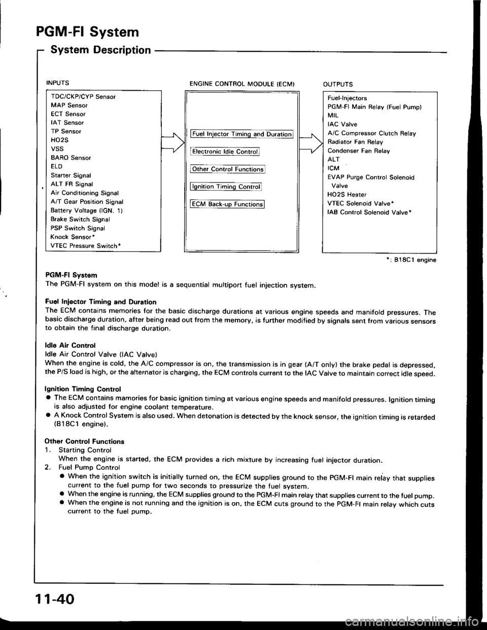
PGM-Fl System
The PGM-Fl system on this model is a sequential multipon fuel injection system,
Fuol Iniector Timing and Duration
The ECM contains memories tor the basic discharge durations at various engine speeds and manifold pressures. Thebasic discharge duration, after being read out from the memory, is turther modilied by signals sent from vanous sensofsto obtain the final discharge duration.
ldle Air Control
ldle Air Control Valve (lAC Vatve)
When the engine is cold, the A/C compressor is on, the transmission is in gear (A/T only) the brake pedal is depressed,the P/S load is high, or the alternalor is charging, the ECM controls current to the IAC Valve to maintain correct idle soeed.
lgnition Timing Controla The ECM contains mamories for basic ignition timing at various engine speeds and manifold pressures. lgnition timingis also adjusted for engine coolant temperature.a A Knock Control System is also used. when detonation is detected by the knock sensof. the ignition timing is retarded(B18Cl engine).
Other Control Functions
1. Starting Control
When the engine is started. the ECM provides a rich mixture by increasing fuel injector duration.2. Fuel Pump Control
a When the ignition switch is initially turned on, the ECM supplies ground to the PGM-Fl main relay that suppliescurrent to the fuel pump tor two seconds to pressurize the tuel system.a When the engine is running, the ECM supplies gfound to the PGM-Fl main relay that supplies current to the fuel pump.a When the engine is not running and the ignition is on, the ECM cuts ground to the PGM-FI main relav which cutscurrent to the fuel pump.
TDC/CKP/CYP Sensor
MAP Senso.
ECT Sensor
IAT Sensor
TP Sensor
HO2S
vss
BARO Sensor
ELD
Starter Signal
ALT FR Signal
Air Conditioning Signal
A/T Gear Position Signal
Battery Voltage {lcN. 1)
Brake Switch Signal
PSP Switch Signal
Knock Sensor'
VTEC Pressure Switchr
Fuel-lnjectors
PGM-FI Main Relay (Fuel Pump)
MIL
IAC Valve
A/C Compressor Clutch Relay
Radiator Fan Relav
Condenser Fan Relav
ALT
rcM
EVAP Purge Control Solenoid
HO2S Heater
VTEC Solenoid Valve'
IAB Control Solenoid Valve*
lFuet tnjector Timing and Duration]
I Electr..l"ldle Contr;il
Fit'e' contr; Funcrfit
l6tio; Ttntrlg c..trol
tEcM aack-,rp Functiorlsl
': 818C 1 €ngine
11-40
Page 233 of 1413
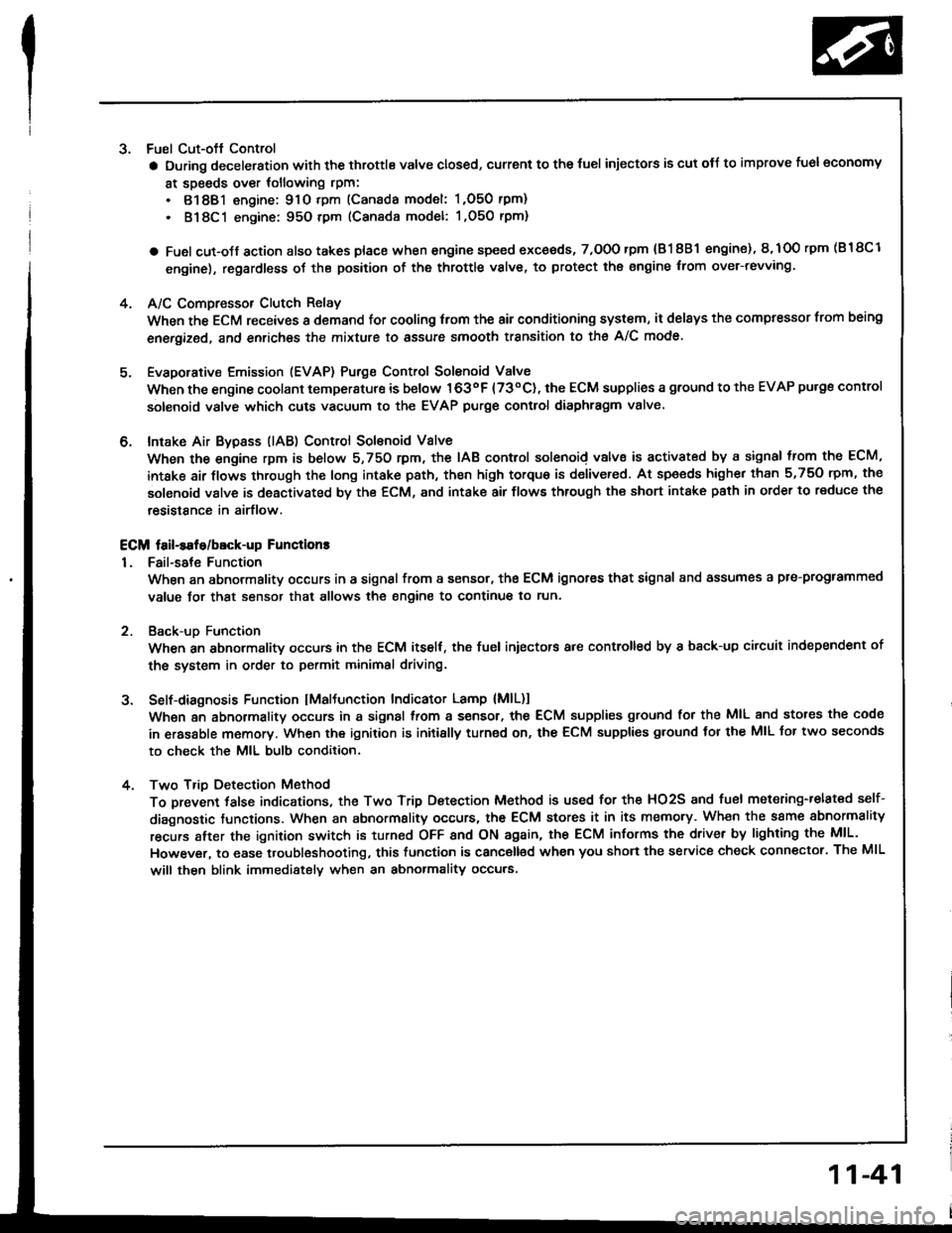
3. Fuel Cut-oft Control
a During deceleration with the throttle valve closed, current to the {uel injectors is cut otJ to improve fuel economy
at speeds over tollowing rpm:
. 8188l engine: 91O tpm (Canada model: 1,O50 rpm)
. 818C1 engine: 95O tpm (Canada model: l,O5O rpm)
a Fuel cut-olf action also takes place when engine speed exceeds, 7,O0O rpm {81 8B1 engine), 8,1O0 rpm (B 18Cl
engine), regardless oI the position of the throttle valve, to protect the engine from ovet-revving.
A/C Compressor Clutch Relay
When the ECM receives a domand for cooling trom the air conditioning system, it del8ys the compressor from being
enetgized, and enriches the mixture to assure smooth transition to the A/C mode.
Evaporative Emission (EVAP) Purge Control Solenoid Valve
When the engine coolant tempersture is below 163oF {73"C), the ECM supplies a ground to the EVAP pu.ge control
solenoid valve which cuts vacuum to the EVAP purge control diaphragm valve.
Intake Air Bypsss (lAB) Control Sol€noid Valve
When the engine rpm is below 5,750 rpm, the IAB control solenoid valve is activated by a signal from the ECM,
intske air flows through the long intake path, then high torque is delivered. At spaeds highe. than 5,750 rpm, the
solenoid valve is deactivated by the ECM, and intake air flows through the short intake path in order to reduce the
resistance in airflow.
ECM fail-safe/bEck-up Functions
1. Fail-sate Function
When an abnormality occurs in a signal from a sensor, the ECM ignores that signal and assumes a pre-progtammed
value tor that sensor that allows the engine to continue to run.
Back-uD Function
When an abnormalitv occurs in the ECM itself, the fuel iniectors are controlled by a back-up citcuit independent of
the system in order to permit minimal driving.
Self-diagnosis Function IMaltunction Indicator Lamp {MlL)1
Wh6n an abnormality occurs in a signal from a sensor, the ECM supplies ground for the MIL and stores the code
in erasable memory. When the ignition is initially turned on, the ECM supplies ground tor the MIL tor two seconds
to check the MIL bulb condition.
Two Trio Detection Method
To prevent tals€ indications, th€ Two Trip Dstection Method is used for the HO2S and fuel metering-related self-
diagnostic tunctions. When an abnormslity occurs, the ECM stores it in its memo.y. Wh€n the ssme sbnormality
recurs alter the ignition switch is turned OFF and ON ag8in, the ECM informs the driver by lighting the MlL.
However, to ease troubleshooting, this function is canc€ll€d when you short the service check connector. The MIL
will then blink immedistelv when an abnormality occurs.
4.
6.
2
4.
11-41
Page 244 of 1413
PGM-FI System
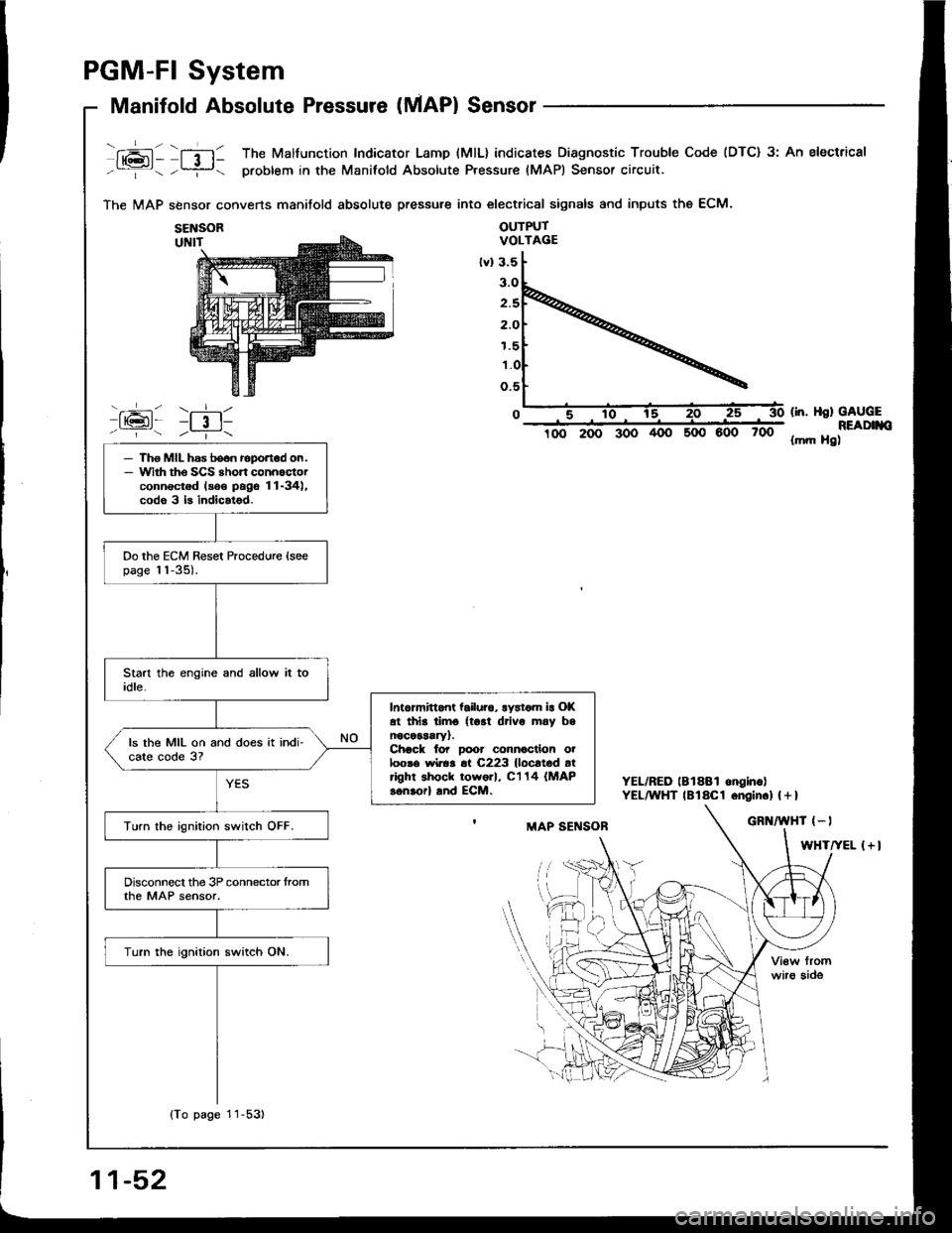
Manifold Absolute Pressure (MAP) Sensor
fxai - lfil1 The Malfunction Indicator Lamp (MlL) indicates Diagnostic Trouble Code (DTC) 3: An electrical
-:- -?- problem in the Manifold Absolute Pressure (MAPI Sensor circuit.
The MAP sbnsor converts manitold absolute pressure into electrical signals and inputs the ECM.
OUTPUTVOLTAGE
600 700
(in. Hsl GAUGEREADIIIO{mft Hg)
YEL/RED lBlSBl onginc)YEL^YHT lBlaCl .ngin.l | + I
{+l
SENSOR
1.5
- Tho MIL has boon roportod on.- Wirh tho SCS rhort connoctorconnectod lsoo pags 11-34),codo 3 b indicatsd.
Do the ECM Reset Procedure {soepage 11-35).
Intormittont tailuro, lystom ir Ol(at thls timo {tort drivo may bsnocessary).Chack to? Door connocllon oiloosa wiroa 6t C223 {locltod atright shock tow6rl, C'l 14 (MAP
sonaorl and ECM.
ls the MIL on and does it indi-cate code 3?
Turn the ignition switch OFF.
Disconnect the 3P connector tromthe MAP sensor,
Turn the ignition switch ON.
{To page 11-53)
11-52
Page 251 of 1413
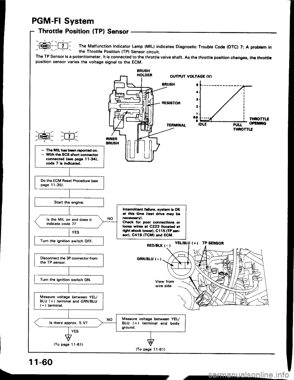
.:-\.-----ll@l--l t l- The Malfunction Indicator Lamp (MtL) indicatee Diagnostic Trouble Cod€ (DTC) 7: A problcm inrhe Thronle Position (TPl Sonsor circuit.The TP Sensor is a potsntiometer, lt is connected to the throttle valve shaft. A8 the throttlo position chan96, the throttlopositaon sensor varies the voltage signal to the ECM.
BBUSHHOLDER
PGM-FI System
Throttle Position (TPl Sensor
OUTPUT VOLTAGE IV)
BNUSH
RESISTOF
IXNOTTII
TERMIIIAL;0rr- of€ no
THNOTTIE
YEL/aLU l+l TP SEITSOR
I
a
t
t
Io.|o
RED/BLK {-I
cnn/BLu I - l
)ran1 )ril-Y- -?..
- Th. MIL h.. baln rlport d on.- With th. SCS thort conn.ciolconn.c-ted (rco pngc 11-341.codo 7 i. indlc.t d.
Do the ECM Reset hocedure (se€page l 'l-35).
l. ..mrtt nt fClur., lyrt m la OX.t thb dm. ll.at drlv. rn.y brncoaataryl.Chack lor poo? connactlo|ra otloora wlr.r !t C223 lloc.t d !tdgtn drod( tow..t, Cl15 ITP ...t-rorl, C419 (TCMI .nd ECM.
ls the MIL on and do€s itindicats codo 7?
Turn th€ ignition switch OFF.
Disconnect tho 3P connector lromth€ TP sensor.
Turn the ignition switch ON.
Meosu.o voltage betwoon YEL/BLU (i ) terminal and GRN/BLUI -, torminal.
Measurs voltagG betw66n YEUBLU (+l terminal and bodygiound.ls there approx. 5 V?
(To page 1 1-611
11-60
(To page 1 1-6'l )
,,,----
Page 256 of 1413
PGM-FI System
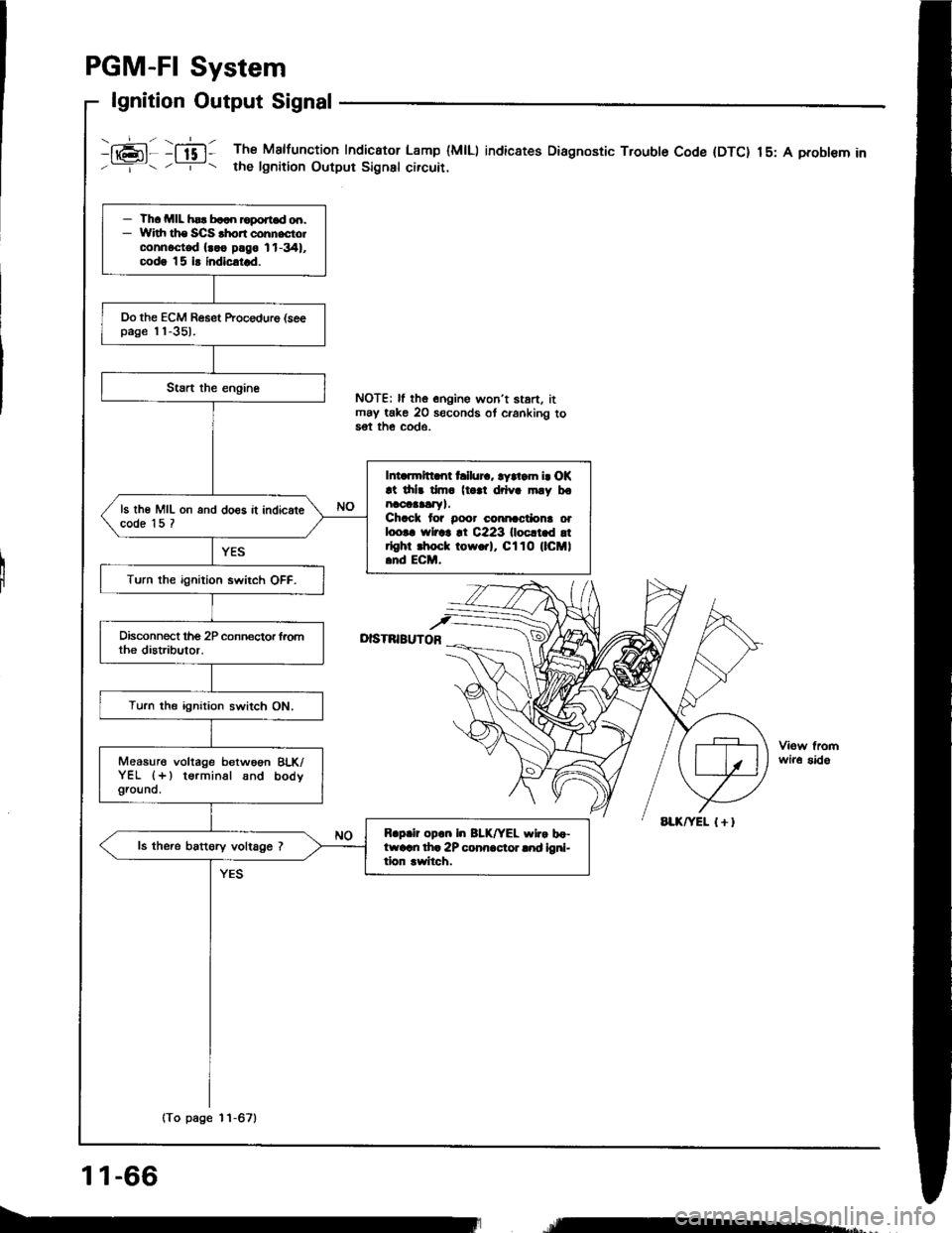
lgnition Output Signal
i16;11 :ffi1 The Malfunction Indicator Lamp (MlLl indic8tes Diagnostic Trouble Code (DTC) 15: A probl€m in'--=-- . -r- t the lgnition Output Signsl circuir.
I
NOTE| ll the onoine won't stan. itmay take 20 seconds ot cranking to5€t th€ COde.
D|STNIBUTOB
wir6 sido
- Th. MIL hsr b..n roport.d od.- Widr ths SCS .hon cohnecto.connoct€d {..o plgo 11-341,codg |5 i! indicatrd.
Do the ECM Reset ftocedure (seepage 'l'l-351.
Intarmltt nt hllur.. ryltam i. OK!t drlr dm. (t |l drlva mly bonaoaaalry).Chack tor Door cmnactiona orloo|. rYlrar !t C223 llocltld !trlghr .hoct tow.rl, Cl10 (lCMl.nd ECM.
ls th€ MIL on and do€s it indicatecode 15 ?
Turn the ignition swirch OFF.
Turn the ignition switch ON.
Measure voltage betwoon BLK/YEL (+) terminal snd bodygrouno.
R.p.ir op.n In BLK/YEL wlr. bo-ftvarn th. 2P conn.cior lnd ioni-tion rwitch.
ls the.e battory voltage ?
(To page 11-67)
11-66
re*,
Page 258 of 1413
PGM-FI System
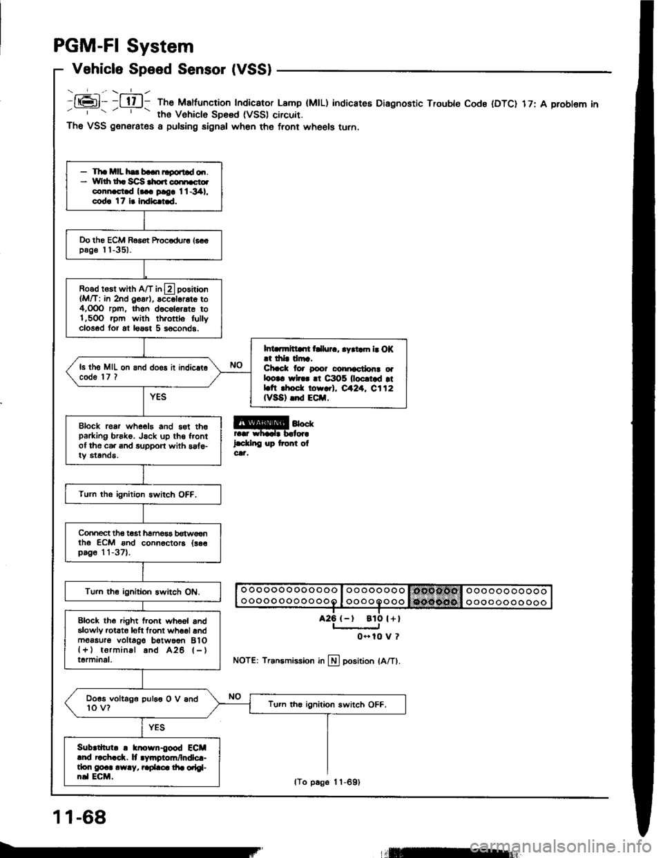
Vehicle Speed Sensor (VSS)
- _-_f_-., \-=1_ -
It6l- -l tl l- The Maltuncrion Indicator Lamp (MtL)' ths Vehiclo SD6sd (VSS) circuit.
indicateE Diagnostic Trouble Code IDTC) 17: A problem in
a25 {-t
The VSS generates a pulsing signal when the front wheels turn.
@4""rr.r whadr b.lor.
l.d.lnC up tront olcat,
NOTE: Transmission in llj position lA/Tl.
- Tha mll hs b..n ltgortld o.r.* Yvlrh th. Sc]S $o.r coi[cto.connast.d l... ploa I l -341,
cod! 17 i. Indlc.i.d.
Do the ECM Basot Procodur6 16€€pag€ I I -351.
Road rosr whh A/T in13 positaon
{M/T: in 2nd O6ar), accol6rat6 to4,OOO rpm, thon d6c6l6,ate to1,5OO .pm with th.ottlo fullyclosod tor at loast 5 s6conds.
Int rmltllrt t llur., .yrtam b O|(.t drlr drr.Chcct lor poor conicctlon! oalootc wl... !t C3O5 0ocrtad rtLtt rhod. torr.l, eA24. C112IVSA) .nd ECil.
ls th6 MIL on and doos it indic.t6code 'l7 ?
Block roar whe€19 and 5st th6parking brsko. Jsck up th€ f.ontof the c6. and support with saf€-iy standa.
Turn the ignition Bwitch OFF.
Connect tho t€st hamos3 b€tw€€ntho ECM ond connoctora {as€pag6 11-37).
Tu.n th€ ignitioh switch ON.
Block the .ight lront whoel andalowly rctato loft tront wh6ol andm6asur6 voltago b€twoon BlO{+) torminal and A26 l-}terminal.
Doss voltago puleo O V and10 v?Tu.n th€ ignition switch OFF.
Sub|tllul. ! knosn{ood ECMlnd r!ch.ck. lt .Vmgiom/lndlc.-tlon g@.. .w.y, r.pLca di. orlgl-n.l ECM.
ato l+l
0- 10 V ?
11-68
lTo p6ge 1 1-691
llEur
Page 265 of 1413
PGM-FI System
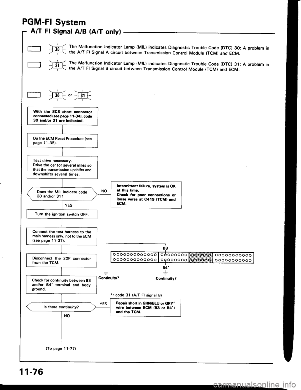
A/T Fl Signal A/B (A/T only)
\[l0l- The Maltunction Indicaror Lamp (MlL) indicates Diagnostic Trouble Code (DTC) 30: A problem In-L= the A/T Fl Signat A circuit between Transmission Control Module (TCMI and ECM.
tItil- The Malfuncrion Indicaror Lamp {MlL) indicates Diagnostic Trouble Code {DTCI 31: A problem In-Li!- the A/T Fl Signal B circuit between Transmission Controt Module (TCM) and ECM.
\.__r_/ \.__r_/-l 30 l- o'-l 3t l------ /----\
84'
+ulty? Continuity?
r: code 31 1A/T Fl signal Bl
11-76
Wlth tho SCS ahon connocrolconi|ocd {!o. p.g. 'l 1 -341, codo3O and/or 31 ars indicltod.
Oo ths ECM Resot Proceduro {seepag€ 'l 1-35).
Test drive necessary.Drive the car lor several miles sothat the transmission uDshifts anddownshilts several times.
Intormittant tsilu.o, sy3tem iB OKat thir tima,Chack lor poor connactions otl.ro!€ wiror at C419 (TCM] andECM.
Does the MIL indicare code30 and/or 31?
Turn the ignition switch OFF.
Connect the test harness to th€main harness only, not to the ECM(see p8go l'l-37).
Disconnect the 22P connectorfrom the TCM.
Check lor continuity between B3andlor 84' terminal and bodygrouno.
Ropair lhon in GRN/8LU or GRY'wiro b6twoon ECM (83 or 84'land tho TCM.
(To page 11-77)
Page 267 of 1413
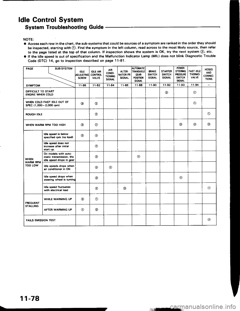
ldle Gontrol System
System Troubleshooting Guide
NOTE:
a Acrosa each row in the chan, the sub-systems that could be sources of a symptom are ranked in the order they should
be inspected, starting with O. Find the symptom in the left column, read across to the most likely source, then reler
to the page listsd at ths top ot that column. It inspection showa the system is OK, try the next system @, etc.
a lf the idle speed is out of sp€cification and th€ Malfunction Indicator Lamp {MlL) does not blink Diagnostic Trouble
Code (DTC) 14, 9o to inspection describ€d on pags 1 1-81.
PAGE
SYMPTOM
IDTIOJUSTIiSCREW
IDLE AIRc0NTROt-
AIRcoN0fTtoNtitcSIGNAL
ALTER.NAION FNSIGNAL
AUTOMATICIRAI{SA(LEGtARP0sm0 stGIAt
ERAK€swrTcHSIGNAL
STARTERswtTcHSIGNAT
POWERSTEERII'IGPffESSUREswncHSIGNAL
FAST IOLETHERMO
HOSESANOCONNEC.TIONS
11-9511-4211-841 1-8611-8811-9011-92I 1-9311-94
DIFFICULT TO STARTENGINE WHEN COLD@o
WHEN COLD FAST IDLE OUT OFSPEC l1,0OO- 2,0OO rpm|o@o
ROUGH IDLEo
WHEN WARM RPM TOO HIGHooo
WHEN
TOO LOW
ldl6 3p6od b b€lowspecitisd rpm (no loadl@o
ldla 5p66d doos nolincraas€ alter initialo
On mod6l3 with auto-matic transmBsion, thsidlo sp€ed drops in 963ro
ldl6 sp€eds drops when8ir condilioner in ONoo
ldls spo6d drops when6ts6iing wh66l i6 turninC@o
ldla spoed lluctust63with alactrical loado
FREOUENTSTALLING
WHILE WARMING UP@o
AFTER WARMING UPo@
FAILS EMISSION TESTo
11-78
.,Hilffirl|,