water pump ACURA INTEGRA 1994 Service Repair Manual
[x] Cancel search | Manufacturer: ACURA, Model Year: 1994, Model line: INTEGRA, Model: ACURA INTEGRA 1994Pages: 1413, PDF Size: 37.94 MB
Page 34 of 1413
![ACURA INTEGRA 1994 Service Repair Manual Design Specifications
]TEMMETRICENGLISHNOIES
: vENSTONSOveralllength 3 DOOR
4 DOOR
Ov€rallWidth
Overall Height 3 DOOR
4 DOOR
Wheelbase 3 DOOR
4 DOOR
Track F/R
Ground Clearance
Seating Capacity
4.38 ACURA INTEGRA 1994 Service Repair Manual Design Specifications
]TEMMETRICENGLISHNOIES
: vENSTONSOveralllength 3 DOOR
4 DOOR
Ov€rallWidth
Overall Height 3 DOOR
4 DOOR
Wheelbase 3 DOOR
4 DOOR
Track F/R
Ground Clearance
Seating Capacity
4.38](/img/32/56982/w960_56982-33.png)
Design Specifications
]TEMMETRICENGLISHNOIES
:' vENSTONSOveralllength 3 DOOR
4 DOOR
Ov€rallWidth
Overall Height 3 DOOR
4 DOOR
Wheelbase 3 DOOR
4 DOOR
Track F/R
Ground Clearance
Seating Capacity
4.380 mm
4.525 mm
'1,710 mm
1,335 mm
1,370 mm
2,570 mm
2,620 mm
't,475/1,470 mm
150 mm
Four (3 DOOR)
172.1in
178.1 in
67.3 in
52.6 in
101.2 in
103.1 in
5|8.1/57.9 in
Five (4 DOOR)
,rerght (usA)cross V€hicle Weight Rating {GVWR)3,680lbs
'le,ght {CANADA)Gross Vehicls Weight Rating {GVWR)1,670 kg
:\GINEType81881 engine
818C1 engine
Cylinder Arrangement
Bore and Stroke
Displacement
Compression Ratio
81881
818C1
81881
B18C I
81881
B 18C1
81881
818C1
engrne
engane
engrne
engine
engine
engine
engine
engine
L!brication Systom
OilPump Displacement
Wster Pump Displacement
FuelRequired
81881
B18C 1
81881
B 18C1
91881
engrne
engrne
engine
engine
engine
818C1 engine
Water-cooled, 4-stroke DOHC
gasoline engine
Watercooled, 4-stroke DOHC
VTEC gasoline engine
Inline 4-cylinder, transverse
81.0 x 89.0 mm
81.0 x 87.2 mm
1,834 cm3 (mf )
1,797 cm3 (m{)
3.19 x 3.50 in
3.19 x 3.43 in
112 cu-in
110 cu-in
9.2:1
10.0 : 1
Eelt driven, OOHC 4 valve per cylinder
Belt driven, DOHC VTEC
4 valve per cylinder
Forced and wet sump, trochoid pump
50, {53 US qt, 44 lmp qt)/minute'l
71 f {75 US qt, 62 lmp qt)/minute"
140 f (148 US qt, 123 lmp qt)/minute*!
140 f (148 US qt. 123 lmp qt)/minute*'
UNLEADED gasoline with 86 Pump
Octane Numb€r or higher
Premium UNLEADED gasoline wilh
91 Pump Octane Number or higher
STARTERTypo
NormalOutput
NominalVoltage
Hour Rating
Direction of Rotation
Weight
Gear reduction
1.4 kW
12V
30 seconds
Clockwise as viewed lrom g6ar end
3.7 k9 | 8.3lbs
CLUTCHClutch Type
Clutch Facing Area
M/TSingle plate dry, diaphragm spring
Torq!e converter
203 cm'� I 31 sq-in
TRANSMISSIONTransmission Type M/T
Primary Reduction
Synchronized 5-speed forward, 1 reverse
Electronically controlled
4-speed automatic. 1 rcverse
Diract 1 : 1
'1: At 6,000 engine
'2: At 7,600 engine
rpm
rpm
(cont'd)
3-17
Page 73 of 1413
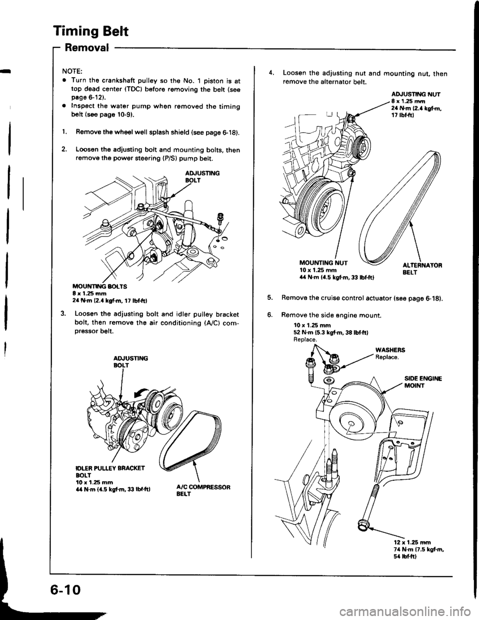
Timing Belt
Removal
I
NOTE:
. Turn the crankshaft pulley so the No. 1 piston is attop d6ad center (TDC) before removing the belt (see
page &12).
a Inspect the water pump when removed the timingbolt {see page 10-9}.
1. Remove thawhe€lwell splash shield (see page 6-18).
2. Loosen ths adjusting bolt and mounting bolts, thenremove the power steering {P/S) pump belt.
MOUivNNG BOLTS8 x 1.25 mm2a N.m 12.4 kgf.m, 1 7 lbt frl
Loosen the adjusting bolt and idler pulley bracket
bolt, then remove the air conditioning (A,/C) com-
oressor belt.
IDLER PUI.IEY BRACKETBOLTl0 r 1.25 mma/a N.m {1.5 kgf.m.33 lbf'ft}
AA,USNNG
ADJUSTING
4, Loosen the adjusting nut and mounting nut, thenremove the alt€rnator belt.
EELTa,l N.m {4.5 kgl.m,33 lbfftl
Remove the cruise control actuator (see page 6-18).
Remove the sid6 sngine mount.
10 x 1.25 mm52 N.m {5.3 kgr'm,38 lbtft}Replace.
MOUNTING NUT10 x 1.25 mm
ADJUSNNG NUT8 x 1.25 mrr2a N.m l2.a lef.m,17 rbl.ftl
12 x 1.25 mm74 N.m 17.5 kgt m,s4 tb{.ftl
Page 75 of 1413
Timing Belt
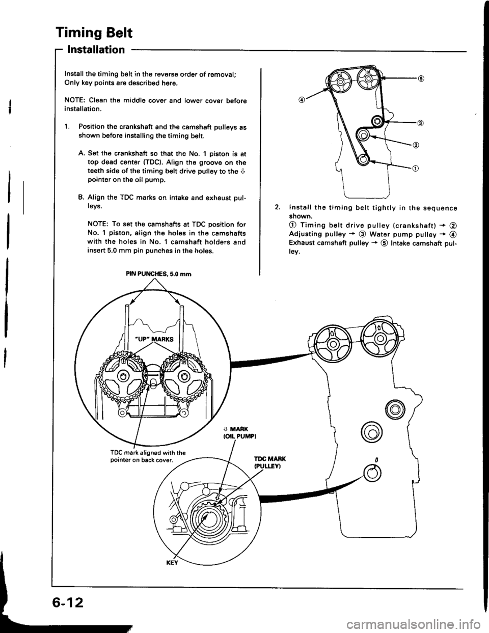
Installation
Install the timing belt in the revorce order of removal;
Only key points are described here,
NOTE: Cl€an the middle cover and lower cover beforeinstallation.
L Position the crankshaft and th€ camshaft pulleys asshown before installing the timing belt.
A. Set the crankshaft so that the No. 1 oiston is at
top dead center (TDC). Align the g.oovo on the
t€eth side of the timing belt d.ive pulley to the Opointer on the oil pump.
L Align the TDC marks on intake and exhaust pul-
tevs,
NOTE: To set the camshafts at TDC position for
No. 1 piston, align the holes in the camshafts
with the holes in No. l camshaft holders andinsert 5,0 mm pin punches in the holes.
PIN PUNCHES, 5.0 mm
2. lnstall the timing belt tightly in the sequence
snown.
O timing belt drive pulley {crankshaft) + @Adjusting pulley * @ Water pump pulley - @Exhaust camshaft pulley + @ Intake camshaft pul-
lev.
TDC mark align6d with thepointer on back cover,TDC MARK
6-12
Page 80 of 1413
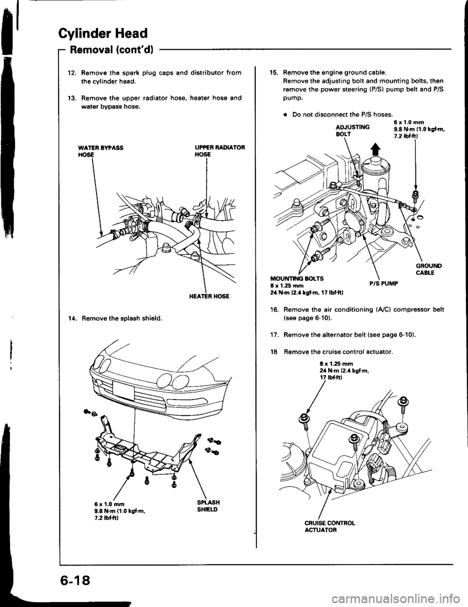
Cylinder Head
Removal (cont'dlI
12.R€move the spark plug caps and distributor from
the cvlinder head.
Remove the upper radiator hose, heater hose and
water bypass hose.
UPPER RAI'IAYOR
14. Remove th6 solash shield.
WATER BYPASS
9.8 N.m {1.0 kgt m.t.2 tbr.frt
sHtEut
15. Remove the engine ground cable.
Remove the adjusting bolt and mounting bolts, then
remove the power steering (P/S) pump belt 8nd P/S
pump.
. Do not disconnect the P/S hoses.
6x1.0mmADJUSTINGBOLT9.8 N.m 11.0 tgfm,7.2 tbf.ftl
8 x 1.25 mm24 .m (2.akstm, 17lbf.ftl
P/S PUMP
Remov€ the air conditioning (Ay'Cl compressor(see pags 6-10).
R€move the alternator belt (see page 6-10).
Ramove the cruise control actuator.
8 x 1.25 mm2a N.m 12.4 kgt m,
belt
17.
t8
ACTUATOR
Page 110 of 1413
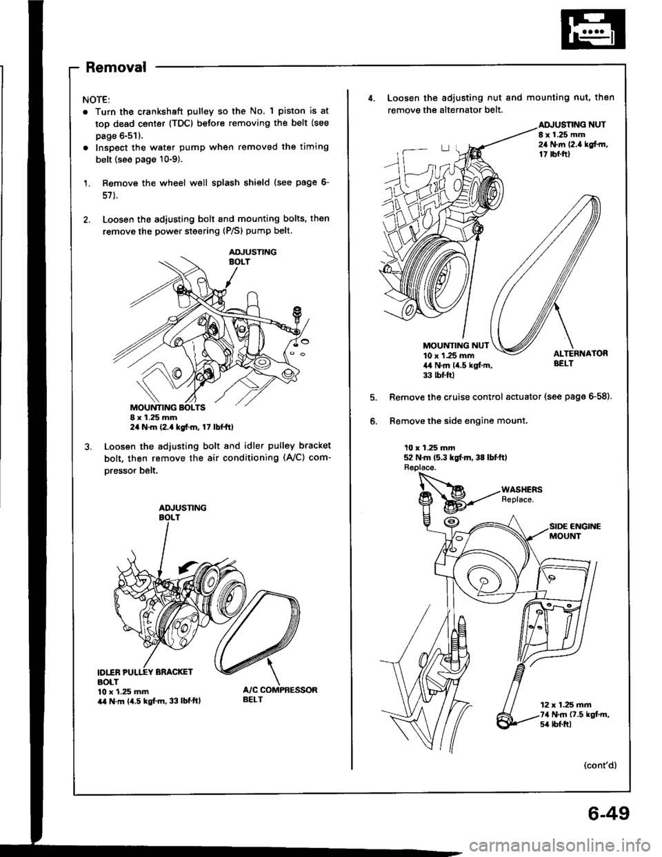
Removal
NOTE:
. Turn the crankshaft pulley so the No. 1 piston is at
top dead center {TDC) before removing the belt (see
page 6-51).
. Inspect the water pump when removed the timing
belt {see page 10-9).
Remove the wheel well splash shield (see page 6-
57 ).
Loosen the adiusting bolt and mounting bolts, then
remove the power steering (P/S) pump belt.
I x 1.25 mm2a N.m l2.a kgt.m, 17 lbt ttl
Loosen the adjusting bolt and idler pulley bracket
bolt, then remove the air conditioning (Ay'C) com-
oresso. belt.
D1INBOLT10 x 1.25 mmira N.m (4.5 kgf.m, 33 lbf'ttl
AOJUSTING
ADJUSNNG
BELT
4. Loosen the adiusting nut and mounting nut, then
remove the alternator belt.
NUTI x 1.25 mm24 N.m {2.a lgf.rn,17 tbf.ftl
MOUNTING NUT10 x 1.25 mm4,t N.m lia.5 kgl.m,33 tbt ftl
Remove the cruise control actuator (see page G58).
Bemove the side engine mount.
10 x 1.25 mm52 N.m 15.3 kgt m, 38 lbtftl
CNGINCMOUNT
12 x 1.25 mm74 N.m (7.5 kgt m,s4 lbf.trl
(cont'd)
6-49
Page 112 of 1413
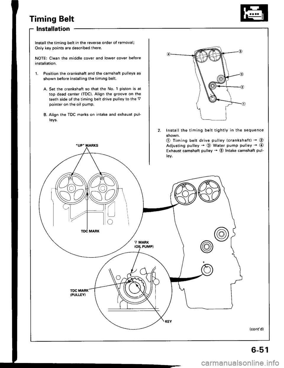
Timing Belt
lnstallation
Install the timing belt in the feverse order of removal;
Only key points are described there.
NOTE: Clean the middle cover and lower cover before
installation.
1. Position the crankshaft and the camshaft pulleys as
shown betore installing the timing belt.
A. Set the crankshaft so that the No. 1 piston is at
top dead center {TDC). Align the groove on the
teeth side of the timing belt drive pulley to the V
pointer on the oil pump.
B. Align the TDC marks on intake and exhaust pul-
leys.
2. Install the timing belt tightly in the sequence
shown.
O Timing belt drive pulley (crankshatt) * @
Adjusting pulley * @ water pump pulley * @
Exhaust camshaft pulley * @ Intake camshaft pul-
lev,
(cont'd)
6-51
Page 118 of 1413
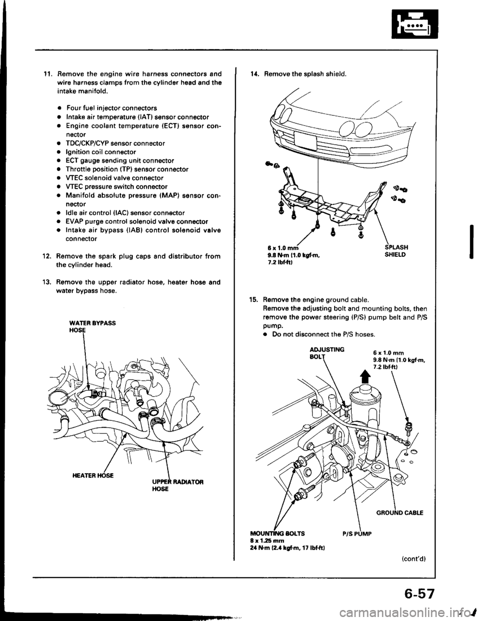
ll.Remove the engine wire harness connectors and
wi.e ha.ness clamps from the cylinder head and the
intake manitold.
Four fuel injector connectors
Intake air tempe.ature {lAT) sensor connector
Engine coolant temperature (ECT) sensor con-
nector
TDC/CKP/CYP sensor connector
lgnition coil conn€ctor
ECT gauge sending unit connector
Throttle position (TP) sensor connector
VTEC solenoid valve connector
VTEC Dressure switch connector
Manifold absolute pressure (MAP) sensor con-
nector
ldle air control {lAC) sensor connector
EVAP purge controlsol€noid valvo connector
Intake air bypass {lABl control solenoid valve
conneclor
a
o
a
o
a
a
a
a
a
a
a
a
a
12.
13.
Remove the spsrk plug caps and distributor from
the cylinder head.
Remove the upper radiator hose, heat€r hose and
water bypass hose.
WATER BYPASS
HOSE
6r1.0mm9.8 N.m (1.0 kgt m,1.2 tbtftl
14. Remove the sDlash shield.
Remove the engine ground cable.
Romovo the adjusting bolt and mounting bolts, then
remove the power steering (P/S) pump belt and P/Spump.
. Do not disconnect the P/S hoses.
(cont'dl
15.
6x1.0mm9.8 N.m 11.0 kgl.m,7.2 tbt.ttl
6-57
,l
Page 185 of 1413
Cooling
lllustrated Index
Radiator
Replacement ............................... 1 O-4
Engine Goolant Refilling and
Bleeding10-5
Cap Testing ............... 10-6
Pressure Testing ......... 10-6
Thermostat
Rep|acement ............................... 1 O-7
Testing .....1O'7
Water Pump
lllustrated Index ......... . 10-8
Inspection .10-9
Replacement ............................... 1 O-9
10-2
Page 192 of 1413
![ACURA INTEGRA 1994 Service Repair Manual Water Pump
NOTE:
a Use new O-rings and new special bolts when reassembling.
a Use liquid gasket, Part No. O8718-0OO1.
3;iil3 B18c1 onsino:
ECT GAUGE SEDING U]{ITI N.m (0.9 tgf.n, 7 lbftt)Apply liquid ACURA INTEGRA 1994 Service Repair Manual Water Pump
NOTE:
a Use new O-rings and new special bolts when reassembling.
a Use liquid gasket, Part No. O8718-0OO1.
3;iil3 B18c1 onsino:
ECT GAUGE SEDING U]{ITI N.m (0.9 tgf.n, 7 lbftt)Apply liquid](/img/32/56982/w960_56982-191.png)
Water Pump
NOTE:
a Use new O-rings and new special bolts when reassembling.
a Use liquid gasket, Part No. O8718-0OO1.
3;iil3 B18c1 onsino:
ECT GAUGE SEDING U]{ITI N.m (0.9 tgf.n, 7 lbf'tt)Apply liquid gaskot
to tho threads.
6r1.Omm
ENGI E COOLAI{TTEMPERATURE IECTI SENSORt8 N.m 11.8 kot.m, 13lbt'ttl
1l t{.m ll.1 tgl.m.8.O tbt.ftl
lllustrated Index
WATER PUMPInspectaon,page lO-9
KNOCK SEI{SOR3l N.m {3.2 kgf.m.23 tbf.ftl(8l8Cl .ngin€ onlyl
WATER OUTLETCOVERApply liquid gasket
to mating sudace.
ECT SEI{SOR
6 r 1.0 mm11 N.m l1.l kgl.m,8.O lbl.ftl
BLEED BOLT9.8 N.m (l.O rg[.m. 7.2 lbt'ft|
Bl8Bl cngln :
OUTIET
ECT SIY]TCH22-26 .m 12.2-2.C )l{/l'nt.
16-19 tbr.ftl
o-Rtt{GRoplaco.
o-itltcRoplrco.
8r1.Orxtr12 .|n ll.2 lgt.m,8.7 n{.ftt
6xt.Omm12 N'ft (1.2 kgf..n.8.7 lbt.ft)
10-8
Page 193 of 1413
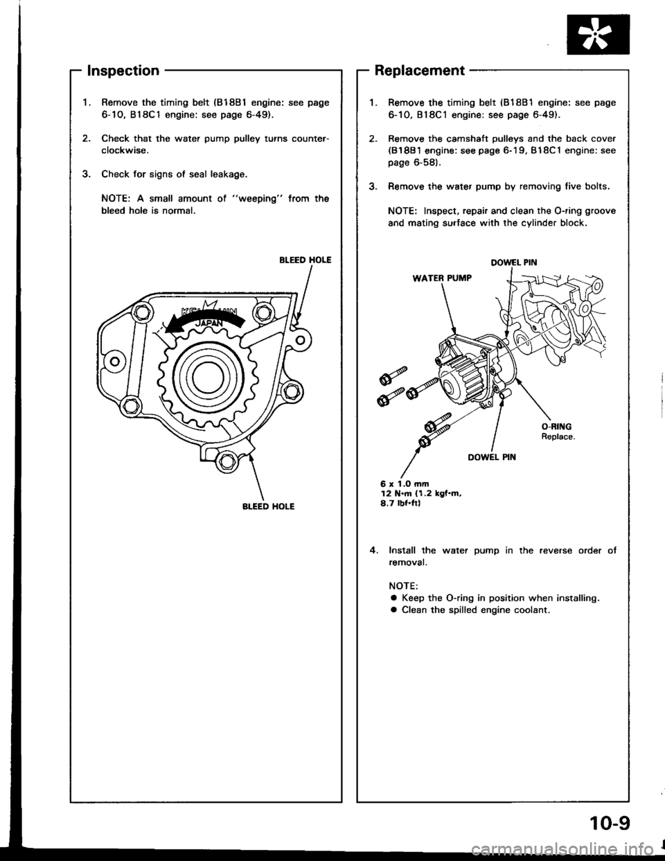
Inspection
Remove the timing belt (81881 engine: see page
6-1O, B18C1 engine: see page 6-49).
Check that the water pump pulley turns counter-
clockwise,
Check for signs ol seal leakage.
NOTE: A small amount ot "weeping" from the
bleed holo is normal,
BLEED HOLE
2.
J.
J.
Replacement
6 r 1.O rnm12 N.m {1.2 kgf.m,4.7 bf.ftl
4. lnstall the water pump in the reverse order
removat.
NOTE:
a Keep the O-ring in position when installing.
a Clean the spilled engine coolant.
Remove the timing belt (818B1 engine: see page
6-10,818C1 engine: see page 6-49).
Remove the camshaft pulleys and the back cover(81881 engine: see page 6-19. B18C1 engine: see
page 6-581.
Remove the water pump by removing five bolts,
NOTE: Inspect, repair and clean the O-ring groove
and mating su.lace with the cylinder block.
DOWEL PIN
BI-EED HOI-E
10-9