alternator ACURA INTEGRA 1998 Service User Guide
[x] Cancel search | Manufacturer: ACURA, Model Year: 1998, Model line: INTEGRA, Model: ACURA INTEGRA 1998Pages: 1680, PDF Size: 53.14 MB
Page 305 of 1680
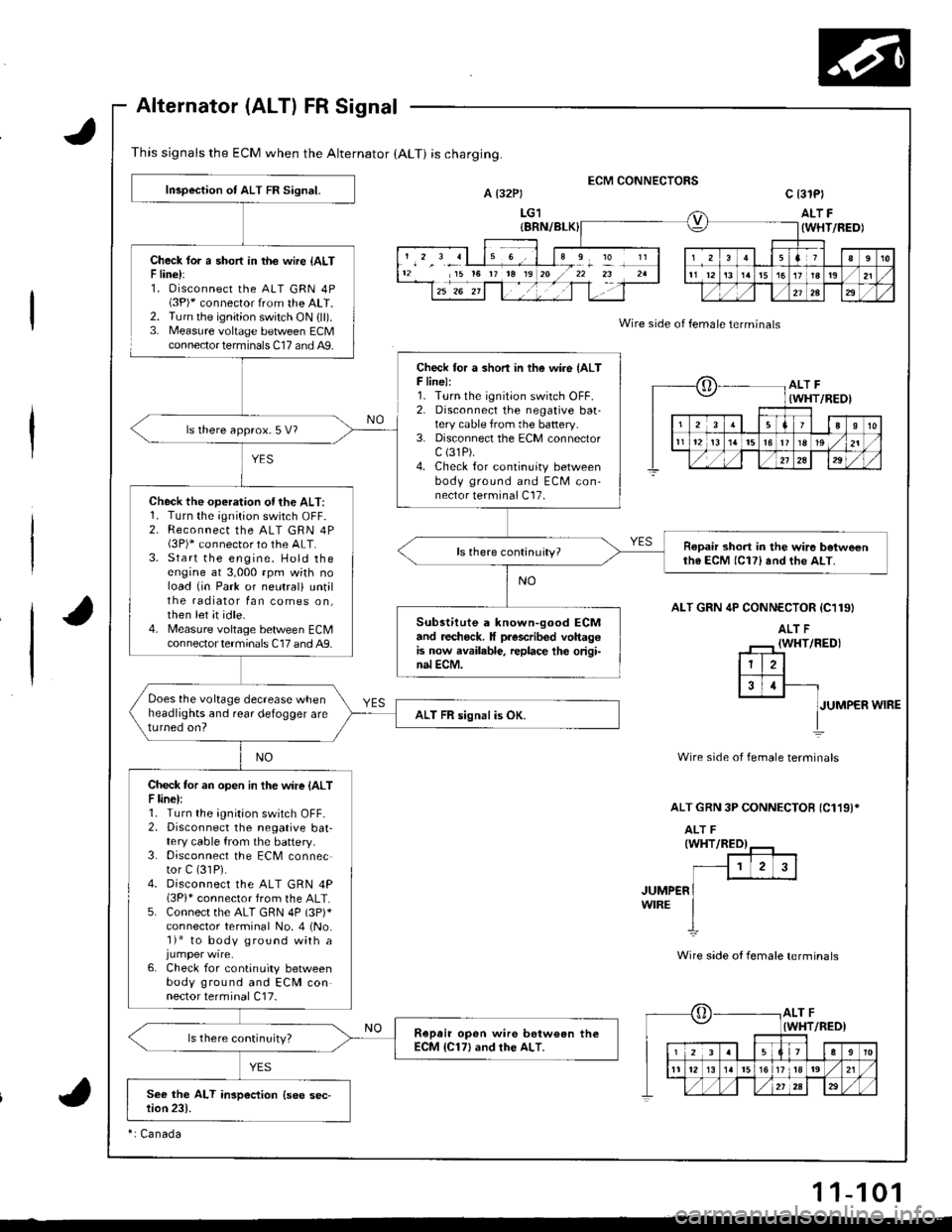
This signals the ECM when the Alternator (ALT) is charging.
Alternator (ALT) FR Signal
Check lor a short in th€ wire {ALTF line):1. Oisconnect the ALT GRN 4P(3P)* connector from the ALT.2. Turn the ignition switch ON {ll).3. Measure voltage between ECMconnector terminals C17 and A9.
ECM CONNECTORSA t32Pt
LG1
c 13lPl
ALT F(WHT/FEDI
Wire side of female terminals
ALT GRN 4P CONN€CTOR {C119}
JUMPER WIRE
Wire side of female terminals
ALT GRN 3P CONNECTOB {C119)*
JUMP€RWIRE
Wire side ot female terminals
12 15 t6 rr t8 19I
?
oALT F(WHT/REOI
23aI10
t112t3t5l6r819 ,/21
./,/,/2a29
[,ALT FIWHT/RED)
12339
11 12l517 tla19 ,/21
Inspection of ALT FR Signal.
Check for a shon in the wire {ALTF line):1. Turn the ignition switch OFF.2. Disconnecl the negative baatery cable from the battery.3. Disconnect the ECM connectorc (31P).
4. Check for continuity betweenbody ground and ECM con-nector terminal C17.
ls there approx.5 V?
Check the operation ofthe ALT:1. Turn the;Onition switch OFF-2. Reconnect the ALT GRN 4P(3P)* connector to the ALT.3. Start the engine. Hold theengine at 3,000 rpm wkh noload {in Park or neutral) untilthe radiator fan comes on,then let it idle.4. Measure voltage bet/veen ECMcon nector termina ls C17 and A9.
Ropair short in the wir6 betweenth6 ECM (C17) and the ALT.
Substitute a known-good ECMand recheck. It prescribed voltagGis now available, replace th€ origi-nal ECM.
Does the voltage decrease whenheadlights and rear defogger areturned on?ALT FR signal is OK.
Check tor an open in the wire {ALTF line):1. Turn the ignition switch OFF-2. Disconnect the negative bat-tery cable from the battery.3. Disconnect the ECM connector C (31P).
4. Disconnect the ALT GRN 4P(3Pi* connector from the ALT.5. Connect the ALT GRN 4P (3p)*
connector terminal No. 4 (No.'l)* to body ground with a
6. Check for continuity betweenbody ground and ECM connector terminal C17.
Ropair open wire bstw€an theECM {C17} and rhe ALT.ls there continuity?
ri Canada
11-101
Page 354 of 1680
fIr
Emission Control System
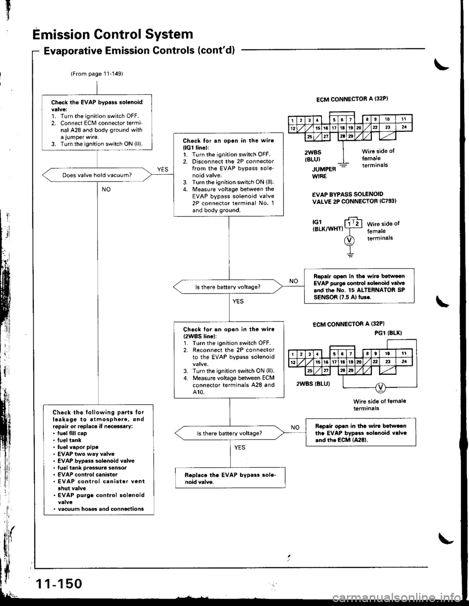
Evaporative Emission Controls (cont'dl
t
ECM CONNECTOR A I32PI
JUMPERWIRE
EVAP BYPASS SOLENOIDVALVE 2P CONNECTOB (C793I
tGl(BLK/WHTIWire side of
femaleterminals
\
ECM CONNECTOR A (32PI
PGl (BLKI
Wire side of lem6l6termrnals
(From page 11-149)
Check iho EVAP bypass solanoid
1. Turn the ignitioo switch OFF.2. Connect ECM connector terminal A28 and body ground witha ,umper wrre.3. Turn the ignition switch ON ill).Chock for an opon in the wire(lGr linell1. Turn the ignition switch OFF.2. Disconnect tho 2P connectorfrom the EVAP bypass sole-noid valve.3. Turn the ignition switch ON (ll).
4. Measure voltage between theEVAP bypass solenoid valve2P connector terminal No. 1and body ground.
Does valve hold vacuum?
Roprir opon in tha wiro batwatanEVAP pu.g6 control solcnoid valvcand thc No. 15 ALTERNATOR SPSENSOR {7.5 Al fu3..
Ch6ck tor an opon in the wile
I2WBS lin6l:'L Tlrrn the ignition switch OFF.2. Reconnect the 2P connectorto the EVAP bypass solenoid
3. Turn the ignition switch ON (ll).
4. Measure voltage between ECMconnector terminals A28 andA10.
Check the following parts lorleakage to atmosphere, andrepsir or roplace if n6ce$try:. fuel fill cap. fuel tank' fuel vapor pipe. EVAP two wsy valve. EVAP bvpess solenoid valve. tuel tank ore33urc son3ot. EVAP control canister. EVAP control canist6r veni3hut valve. EVAP purg. control solenoid
. vacuum hoses and conn6ctions
Rcpair opan in thc wira botwa.nth. EVAP byp!.s sobnoid valvc.nd tfi. ECM lA28l.
3Ia10't1
12l61611t8t9dta22a2a
x272tz3
2WBSIBLUI
wire side ol
femal€terminals
1 1-150
Page 1057 of 1680
J
Electrical
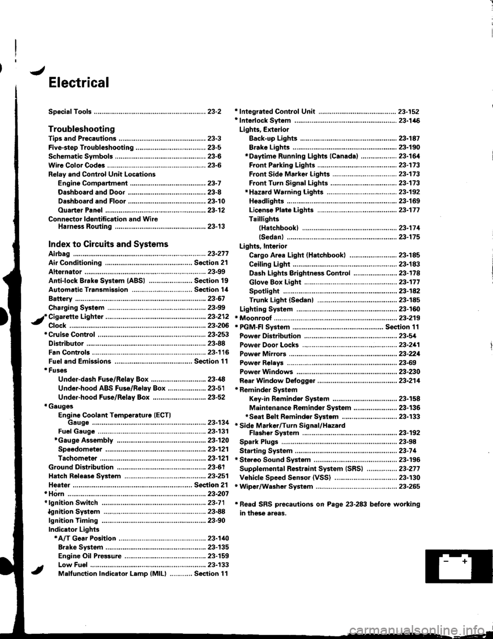
Speciaf Toofs ..........................23-2
Troubleshooting
Tips 8nd Precautions .......................,..,.,.,.,.,......,..., 23-3
Five-step Troubleshooting ............,......,.,.,...,..,....., 23-5
Schsmatic Svmbols ...............23-6
Wire Color Code3 .. ................. 23-6
Relay and Control Unit Locations
Engine Compartment ......,.,.................,.,.,.,.,.,,,, 23-7
Dashboard and Door .........,...........,.....,.,....,.,.... 23-8
Dashboard and Floor ......................................... 23-10
Ouarter Pan€f .,,.,...,.,..,...,,,23-12
Connector ldontification and WireHarness Routing ......,.,......23-'13
Index to Circuits and Systems
Airbag
* Integrated Control Unit .....,.,.,.....23-152* Interlock Sytem .,...,.,...........,. 23.146
Lights, Exterior
Eack-up LighB ..................23.187
Brake Ligh$ ......................23-190*Daytime Running Lights (Canada) ................... 23"164
Front Parking Lights .......................................... 23-173
Front Side Marker Lights .................................. 23-173
Front Turn Signal Lights ..................-.......,...,.,. 23-173* Hazard Warning Lights ....................,........,....... 23-192
Headlights.....23-169
23-253 powerDistribution..................... 23-5/r
Air Conditioning.....,....... Soction 21
Alternator ..........,................... 23.99
iCigarette Lighter .........23-212
*Cruise Control
Distributor
'.'.,.'.'.,.'...,,,,.,''.'.,.',.'''.' 23.277
.............................. 23.88
................... 23-90lgnition Timing ......
Indicator Lights
Key-in Reminder System
Maintenance Reminder System*Seat Belt R€mindor System .,...........................* Side Marker/Turn Signal/HazardFlashcr Svstem .................23-192
Spark Plugs ............................23-98
Starting System .....................23-74* Stereo Sound System ...,......,..........,...,......,.,.,.,..,., 23-196
Supplemental Restraint System (SRS) ................ 23-277
Vshicle Speed Sensor (VSS) ................................. 23.130r Wiper/Washer System .........................................., 23-265
*Read SRS precautions on Psge 23-283 before working
in those areas,
23-154
23.136
23"133
Page 1059 of 1680

Troubleshooting
Tips and Precautions
Never try to disconnect connectors by pulling on their
wires; pull on lhe connector halves instead.
Alwavs reinstall Dlastic covers.
Before connecting connectors, make sure the termi-
nals are in Dlace and not bent.
a Check lor loose retainer and rubber seals.
The backs of some connectors are packed with
grease. Add grease if needed. lf the grease is contami-
nated, reolace it.
(cont'd )
RETAINER
K
Bef ore Troubleshooting
a Check applicable tuses in the appropriate fuse/relay
box.
Check the battery for damage, state of charge, and
clean and tight connections.
Check the alternator belt tension.
CAUTION:
a Do not quick-charge a battely unless the battery
ground cable has been disconnected. otherwise
you will damage the alternator diod€s.
a Do not attempt to crank the engine with the bat-
tery ground cable loosely connected or you willse-
verely damage the wiring.
a The originsl radio has a coded theft plotection cir-
cuit. Be sure to get the customel's code numbel
before- disconnecting the battsry.- removing the No. 47 (7.5 A) fuse from tho
under-hood luse/relay box.- removing the radio.
Atter service. leconnect Dower to the radio and
tum it on. When the word "CODE" is displayed,
enter the customer's 5-digit code to restore radio
ooeration.
Handling Connectors
a Make sure the connectors are clean and have no loose
wire terminals.
a Make sure multiple cavity connectors are packed with
grease (except watertight connectors).
a All connectors have push-down release type locks.
LOCKING TAB
LOCKING TAB
Some connectors have a clip on their side used to at-
tach them to a mount bracket on the body or on
another component. This clip has a pull type lock.
Some mounted connectors cannot be disconnected
unless you tirst release the lock and remove the con-
nector from its bracket.
LOCKINGPAWL ONOTHERHALF OFCONNECTORPull todisengageBRACKET
Page 1072 of 1680

Connector ldentification and Wire Harness Routing
Connectot or
Terminal
Numbel of
CavitiesLocationConnects toNotes
c'to 1
c102
c103
c'1 04
c105
c106
c 107
c108
c108
c109
c110
c112
c113
c'r 14
c115
c116
c117
c118
ct'l9
c119
c120
c121
c122
c124
c't 26
c127
c128
c129
c130
c111
4
10
14
6
I
1
2
2
10
2
3
2
J
4
3
3
2
2
I
3
2
2
2
2
2
I
2
14
Right side of engine compartment
Right side of engine compartment
Right side ot engine compartment
Right side of engine compartment
Right side oI engine compartment
Right side of engine
Right side of engine
Transmission
Transmission
Middle ot engine
Middle ot engine
Right side of engine
Right side of engine compartment
Middle rear of engine compartment
N4iddle of engine
N4iddle ol engine
Middle oI engine
Nliddle ot engine
Middle of engine
Lelt side of engine
Left side of engine
Middle of engine
Middle oI engine
Middle of engine
Middle of engine
Middle ot engine
Left side of engine compartment
Lelt side ot engine compartment
Left side of engine compartment
Transmission
Transmission
Transmission
Main wire harness (C221)
Main wire harness (C222)
Main wire harness 1C223)
lvlain wire harness (C220)
Starter solenoid
Engine coolant temperature (ECT)
sensor
Engine coolant temperature (ECT)
gauge sending unit
Back-up light switch
Lock-up control solenoid valve A and B
Distributor
Crankshatt speed fluctuation (CKF)
sensor
Engine coolant temperature (ECT)
switch
Vehicle speed sensor (VSS)
Primary HO2S
MAP sensor
Throttle position (TP) sensor
ldle air control (lAC) valve
EVAP purge control solenoid valve
Engine oil pressure switch
Alternator
Alternator
lntake air temperature (lAT) sensor
No. 1 fuel injector
No. 2 fuel injector
No. 3 fuel injector
No. 4 fu€l injector
Junction connector
Engine compartment wire harness
(c304)
Engine compartment wire harness
(c30s)
Shift control solenoid valve A and B
Countershaft speed sensor
lvlainshaft speed sensor
M/T
NT
USA
Canada
Afi
Afi
T101
T102
Left side oI engine
Right side of engine compartment
Alternator
Under hood fuse/relay box
G'1 01Right side oI engineEngine ground. via engine wire
harness
Engine Wire Harness (B188l enginel
23-16
Page 1074 of 1680

Connector ldentification and Wire Harness Routing
Engine Wire Harness (B18Cl enginel
Connectol ol
Terminal
Number of
CavitiesLocationConnects toNotes
c 101
c102
c103
c104
c105
c106
c101
c108
cr09
c110
c'r 11
cl12
c1't3
c114
c115
c116
cl17
c118
c119
c119
c120
cI2'l
cl24
c126
c127
cl31
c132
c133
c134
10
14
3
1
2
1
2
10
2
'I
3
2
2
2
I
1
2
2
?
3
2
14
Right side of engine compartment
Right side of engine compartment
Right side of engine compartment
Right side ol engine compartment
Right side of engine compartment
Righr side oI engine
Right side of engine
Transmission
Middle of engine
Middle of engine
Right side of engine
Right side of engine compartment
Middle rear of engine compartment
Middle of engine
Middle of engine
Middle of engine
Middle of engine
i/iddle of engine
Left side ot engine
Lelt side ot engine
Middle ot engine
Middle of engine
Middle of engine
Middle of engine
Middle of engine
Left side of engine companment
Left side of engine compartment
Lelt side of engine compartment
Right side of engine
Right side of engine
Middle of engine
Middle of engine
lvlain wire harness (C221 )
Main wire harness {C222)
Main wire harness (C223)
Main wire harness (C220)
Starter solenoid
Engine coolant temperature (ECT)
sensor
Engine coolant temperature (ECT)
gauge sending unit
Back-up light switch
Distributor
Crankshalt speed fluctuation (CKFI
sensor
Engine coolant temperature {ECT)
switch
Vehicle speed sensor (VSS)
Primary HO2S
MAP sensor
Throttle position {TP) sensor
ldle air control (lAC) valve
EVAP purge control solenoid valve
Engine oil pressure switch
Alternator
Alternator
Intake air temperature llAT) sensor
No. 1 fuel injector
No. 2 fuel injector
No. 3 tuel injector
No. 4 tuel injector
Junctron connector
Engine compartment wire harness(c304)
Engine companment wire harness(c30s)
VTEC solenoid valve
VTEC oil pressure switch
Knock sensor (KS)
Intake air bypass {lAB) control sole-
noid valve
USA
Canada
T101
r 102
Left side ot engine
Right side of engine compartment
Alternator
Under-hood fuse/relay box
G 101Right side of engineEngine ground, via engine wire
naaness
23-18
Page 1105 of 1680
T
I
1
J)
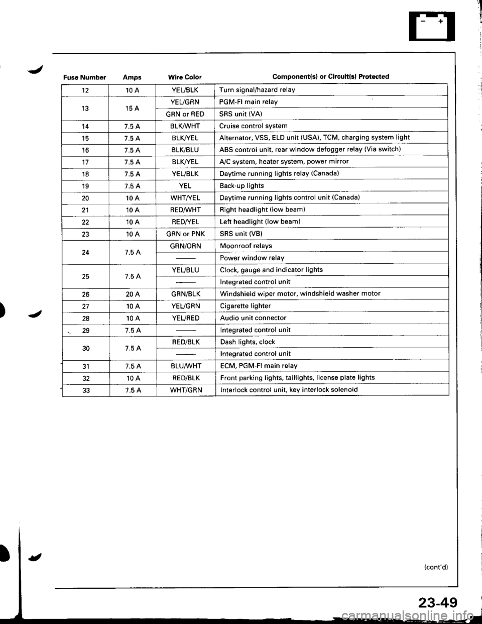
Fuso NumberWire ColorComponent{s} or Circuit(rl ftqt6cted
't210AYEUBLKTurn signal/hazard relay
15 AYEUGRNPGM-Fl main relay
GRN or REDSRS unit (VA)
147.5 ABLK/WHTCruise control system
15BLK/YE LAlternator, VSS, ELD unit (USA), TCM, charging system light
't67.5 ABLVBLUABS control unit, rear window defogger relay (Via switch)
117.5 ABLK//ELAVC system, heater system, power marror
187.5 AYEUBLKDaytime running lights relay (Canada)
197.5 AYELEack-up lights
2010 AWHT/YELDaytime running lights control unit (Canada)
2110 ARED/WHTRight headlight (low beam)
2210 ARE D|YE LLett headlight (low beam)
2310 AGRN or PNKSRS unit (VB)
247.5 AGRN/ORNMoonroof relays
Power window relay
7.5 AYEUBLUClock, gauge and indicator lights
Integrated control unit
2620AGRN/BLKWindshield wiper motor, windshield washer motor
10AYEUGRNCigarette lighter
2810AYEUREDAudio unit connector
29Integrated control unit
30RED/BLKDash lights, clock
Integrated control unit
317.5 A8LU/WHTECM. PGM-Fl main relav
10ARE D/BLKFront parking lights, taillights, license plate lights
7.5 AWHT/GRNInterlock control unit, key interlock solenoid
23-49
Page 1110 of 1680
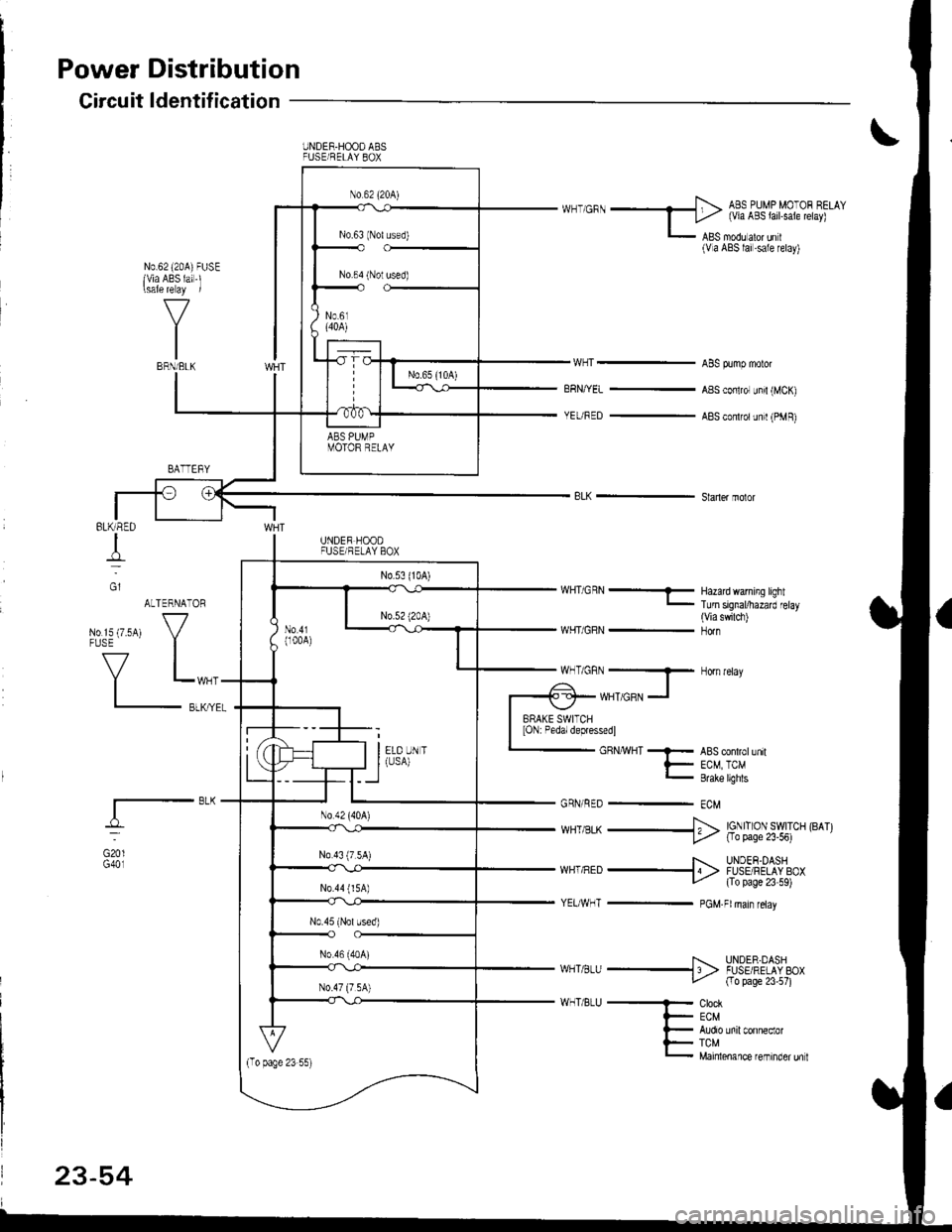
Power
Circuit
Distribution
ldentification
UNDER.HOOO ABSFUSE/RELAY 8OX
ABS OUMP MO'OF CELAY
I Li,z (via ABS lail.sale telay)
L lgS moou aror un r(Va ABS lai.sale retay)
N0.62 (20A)FUSElvia ABS lai-l\sale re ay /
ABS pump motor
ABS conlrol unir (MCK)
ABS con$olunit (PMR)
Hazad warning lightTurn signal/hazard elay(Viaswilch)Horn
BRN/YEL
YEUFED
8LK - Shner molor
BLK/RED
T
G1
GmlG401
ALTERNATORwHriGRN---
WHT/GRN -No rs {7.5A1 V"LL,,r,
_f,-"*
GRNMHT -F ABS conlrollnrt
t- EcM TcM_ &eke ughts
GRN/RED - ECM
*HT,BLK --+ ig|ryJ,itil.* F^r
F UNDEF OASHvlHi.nED -I4 > FUSE FELAY BOXLz {To page 23 59)
YEITWHT - PGM.Flmain retav
T. UNDER.DASHI/HT a_U -l 'l > .uSE RELAV 8OXfro page 23 57)
ClockECM
TCMMainlenance reminder unl
MT/GRN --T Horn relav
-ol- WHTTGRN -l
BRAKE SWITCHION: Pedal depressedl
23-54
Page 1155 of 1680
)
)
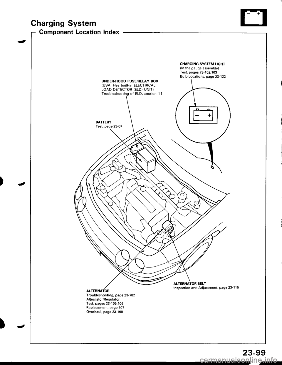
Charging System
Component Locationlndex
CHARGING SYSTEM LIGHT(ln the gauge assembly)Test, pages 23-102,103Bulb Locations, page 23-122
UNDER-HOOD FUSE/RELAY BOX(USA: HAS bUiIt-iN ELECTRICALLOAD DETECTOR (ELD) UNIT}Troubleshooting of ELD, secrion 11
BATTERYTest,
ALTERNATOR BELTInsp€ction and Adiustment, page 23_115ALTERNATORTroubleshooting, page 23'102Alternator/FegulatorTosl, pages 23-105,'106Replacement, page 107Overhaul, page 23-108
23-99
.t-
Page 1156 of 1680
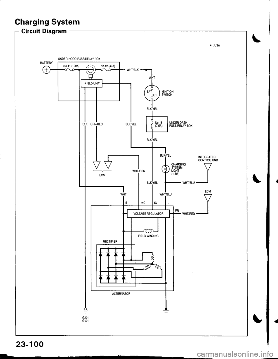
a
Charging System
Circuit Diagram
INTEGRATEOCONTROL UNIT
V
II
ECM
V
II
UNDER.HOOD FUSE/RELAY BOX
No41 (1tl0A) /^ N0.42 (40A)
FIETDWINOING
WHT/8LU
L
GFN/REO
I
I
I
I-t
-"
ALTERNATOR
BLK/YEL
23-100
I-