relay ACURA INTEGRA 1998 Service User Guide
[x] Cancel search | Manufacturer: ACURA, Model Year: 1998, Model line: INTEGRA, Model: ACURA INTEGRA 1998Pages: 1680, PDF Size: 53.14 MB
Page 240 of 1680
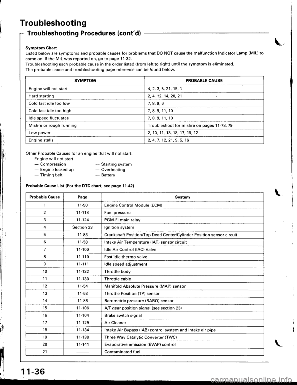
Troubleshooting
Troubleshooting Procedures (cont'd)
Symptom Chart
Listed below are symptoms and probable causes for problems that DO NOT cause the malfunction Indicator Lamp (MlL) to
come on. lf the MIL was reported on, go to page 11-32.
Troubleshooting each probable cause in the order listed (from left to right) until the symptom is eliminated.
The probable cause and troubleshooting page relerence can be found below.
Other Probable Causes for an engine that will not start:
Engine will not sta rt- Compression- Engine locked up- Timing belt
\_
- Starting system- Overheating- Battery
'4,
It
Probable Cause List (For the DTC chart. see page 11-421
Probable CausePageSystem
111-50Engine Control Module (ECM)
211118Fuel pressure
311-124PGM-Fl main relay
4Section 23lgnition system
51 1-83Crankshaft Position/ToD Dead Center/Cylinder Position sensor circuit
11-58Intake Air Temperature (lAT) sensor circuit
71 '�t- 100ldle Air Control (lAC) Valve
811110Fast idle thermo valve
I11lllldle speed adjustment
'1011-132Throttle body
111 1-130Throttle cable
1211-54lvlanifold Absolute Pressure {MAP) sensor
IJ1163Throttle Position {TP) sensor
1411-86Barometric pressure (BARO) sensor
1 '1 106A/T gear position signal {see section 23)
16'1 1 104Brake switch signal
1711 129Air Cleaner
181 1- 134Intake Air Bypass {lAB} control system and intake air pipe
19'1 1 138Three Way Catalytic Convener (TWC)
2011-141Evaporative emission (EVAP) control
21Contaminated fuelll ll 21 | - | cont"-in"t"o tu"
11 l-
I
,l 11-36
-
SYMPTOMPROBABLE CAUSE
Engine will not stan4, 2, 3,5, 21, 15, 1
Hard starting2, 4, 12, 14,20,21
Cold fast idle too low
Cold fast idle too high7, 8, 9, 11, r0
ldle speed fluctuates7,8,9,11,10
Misfire or rough runningTroubleshoot for misfire on pages 11-78,79
Low power2, 10,'t1, 13, 14, 17, 19, 12
Engine stalls2, 4,1 , 12,21,9, 5, 16
Page 243 of 1680
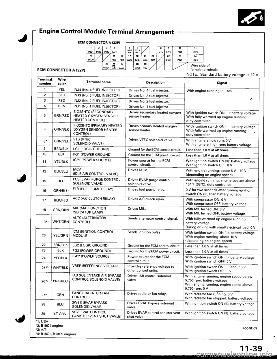
Engine Control Module Terminal Arrangement
ECM CONNECTOR A I32P}
ECM CONNECTOR A I32PI
*1: USA*2:818C1 engine*3:A,/T*4: 818C1, 818C5 engines
female terminals
NOTEr Standard battery voltageis 12 V.
{cont'di
LG22A
TerminalWireTerminal nameDescriptionSignal
YELlNJ4 (No. 4 FUEL INJECTOR)Drives No. 4 fuel iniector.With engine running: pulses2BLUlNJ3 (No.3 FUEL INJECTOR)Drives No. 3 fuel injector.
3REDlNJ2 (No.2 FUEL INJECTOB)Drives No.2 fuel injector.
BRNlNJl (No. 1 FUEL INJECTOR)Drives No. l Iuel iniector.
5GRN/REDS 02SHTC (SECONDARY
HEATED OXYGEN SENSORHEATER CONTROL)
Drives secondary heated oxygensensor heater,With ignition switch ON (ll)i battery volrageWith fully warmed up engine runningiduty controlled
6ORN/BLKP O2SHTC {PRIMARY HEAIEDOXYGEN SENSOB HEAIERCONTFOL)
Draves primary heated oxygensensor heater,With ignition swirch ON (ll): battery voltageWith lully warmed up engine running:duty controlled
84G RNI/ELVTS (VTEC
SOLENOID VALVE)Drives VTEC solenoid valve.With engine at low rpm: 0 VWith engine at high rpm: battery voltageIBRN/BLKLG1 (LOGIC GROUND)Ground for the ECM control circuit.Less than 1.0 V at alltimes10BLKPGl (POWER GROUND)Ground for the EC[, power circuit.Less than 1.0 V at all times't'lYEUBLKIGPl {POWER SOURCE)Power source for the ECMcontrolcircuit.With ignition switch ON 1ll): battery voltageWith ignition switch OFF| 0 V
12BLI(8LUIACV(IDLE AIR CONTROL VALVE}Drives IACV.With engine running: about 6 V 10 V(depending on engine speed)
REDPCS (EVAP PURGE CONTROLSOLENOID VALVE)Drives EVAP purge controlsolenoid valve.Wilh engane running, engine coolant above154"F (68'C): duty controlled
GRN/BLUFLR (FUEL PUMP RELAY)Drives fuel pump relay.0 V for two seconds after turning ignitionswitch ON (ll), then battery voltage
17B LVBEDACC (fuC CLUTCH RELAY)Drives A,/C clulch relay.With compressor ON: 0 VWith compressor OFFt baftery voltage
18GRN/ORNMIL (I\4ALFUNCTION
INDICATOR LAMPiDrives MlL.With MIL turned ON:0 VWjth MIL turned OFF: battery vottage
19*,WHT/GRNALTC (ALTERNATOR
CONTROL)Sends alternator control signal,With fully warmed up engine runninglbattery voltageDuring driving with small electrical load: 0 V
20YEUGRNICM (IGNITION CONTROLMODULE)Sends ignition pulse.With ignition switch ON (ll): battery voltageWith engine running: about'10 V(depending on engine speed)22BRN/BLKLG2 (LOGIC GROUND)Ground forthe ECM controlcifcuit.Less than 1.0 V at all times8LKPG2 (POWEfl GROUND)Ground for the ECM power circuit.Less than 1.0 V at all times
24YEUELKIGP2 (POWER SOURCE)Power source for the ECMcontrolcircuit,With ignition switch ON {lli: battery voltageWith ignition switch OFF: 0 V
25*3WHT/BLKVREF (REFERENCE VOLTAGE)Provides reference voltage toother control units,With ignition swirch ON (ll): about 5 VWath ignition switch OFF: 0 V
26. 'PNK/8LU
IAB SOL (INTAKE AIR BYPASSCONTROL SOLENOID VALVE)Drives IAB conlrol solenoidWith engrne running, engrae speed betow5,750 rpm: battery voltageWith engine running, engine speed above5,750 rpm: 0 V
27* IGRNFANC (BADIATOR FANCONTROL)Drives radiator fan relay.With radiator {an running: 0 VWith radiator Ian stopped: battery voltage
2ABLU2WBS (EVAP BYPASSSOLENOID VALVE)Drives EVAP bypass solenoidWith ignition switch ON (ll): battery vottage
29LT GRNVSV (EVAP CONlROLCANISTER VENT SHUT VAVLE)Drives EVAP control canister ventshut valve.Wilh ignilion switch ON lll): banery votrasc
1 1-39
Page 252 of 1680
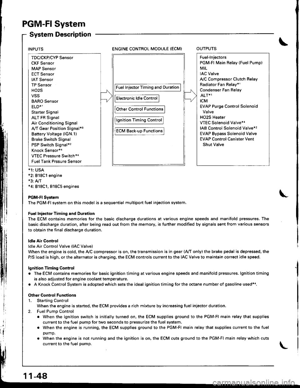
PGM-FI System
System Description
ENGINE CONTROL MODULE (ECM)OUTPUTS
*1: USA*2: 818C1 engine*3: A,/T*4: 818C1, 818C5 engines
PGM-FI Sy3tem
The PGM-Fl system on this model is a sequential multiport fuel injection system.
Fuel lniector Timing and Duration
The ECM contains memories for the basic discharge durations at various engine speeds and manifold pressures. The
basic discharge duration, after being read out from the memory. is further modified by signals sent from various sensors
to obtain the final discharge duration.
ldle Air Control
ldle Ai. Control Valve (lAC Valve)
When the engine is cold, the Ay'C compressor is on. the transmission is in gear (Ay'T only)the brake pedal is depressed, the
P/S load is high, or the alternator is charging, the ECM controls current to the IAC Valve to maintain correct idle speed.
lgnition Timing Control
. The ECM contains memories for basic ignition timing atvarious engine speeds and manifold pressures, lgnitiontiming
is also adjusted for engine coolant temperature.
. AKnockControl System isadoptedwhich sets the ideal ignition timing for the octane n um ber of gasoline used*r,
Other Control Functions
L Starting Control
When the engine is started, the ECM provides a rich mi{ure by increasing fuel injector duration.
2. Fuel PumD Control
. When the ignition switch is initially turned on, the ECM supplies ground to the PGM-FI main relay that supplies
current to the fuel pump for two seconds to pressurize the fuel system.
. When the engine is running, the ECM supplies ground to the PGM-FI main relay that supplies current to the fuel
DUmO.
. When the engine is not running and the ignition is on. the ECM cuts ground to the PGM-FI main relay which cuts
current to the fuel oumo.
INPUTS
TDc/CKP/CYP Sensor
CKF Sensor
MAP Sensor
ECT Sensor
IAT Sensor
TP Sensor
HO2S
VSS
BARO Sensor
ELD*1
Starter Signal
ALT FR Signal
Air Conditioning Signal
A,/T Gear Position Signal*3
Battery Voltage (lGN.1)
Brake Switch Signal
PSP Switch Signal*'�
Knock Sensor*1
VTEC Pressure Switch*4
Fuel Tank Prssure Sensor
Fuel InjectorTiming and Duration
Electronic ldle Control
Other Control Functions
lgnition Timing Control
ECM Back-uD Functions
Fuel-lnjectors
PGM-Fl Main Relay (Fuel Pump)
MIL
IAC Valve
A,/C Compressor Clutch Relay
Radiator Fan Belay*1
Condenser Fan Relay
ALT*1
rcM
EVAP Purge Control Solenoid
Valve
H02S Heater
VTEC Solenoid Valve*'
IAB Control Solenoid Valve*,
EVAP Bypass Solenoid Valve
EVAP Control Canister Vent
Shut Valve
11-48
Page 254 of 1680

I
I
It:
PGM-FI System
Engine Control Module {ECMI
,i
I
{
ili
NOTE: lf this svmotom is intermittent, check for a loose fuse No. 25 METER (7.5A) in the under_
dash fuse/relay box, a ooor connection at ECM terminal A18, or an intermittent open in the
GRN/ORN wire between the ECM (A18) and the gauge assembly.
Wire side of female terminals
I
The Mellunction Indicator Lamp(MlLl never com€3 on leven foltwo secondsl alter ignition islurn6d ON lll).
Turn the ignition switch ON (lli.
- Repair short or open in th€wire betwe€n No. 25 METER{7.5 A}fuse and gauge assem-bty.- ReDlaco No.25 METER 17.5 A)fuse.
ls the low oil pressure light on?
Try to start the engine,
Check for an open in ih6 wires
IPG lines):1. Turnthe ignition switch ON (ll).
2. Measure voltage betweenbody ground and ECM connec-tor terminals A10 and A23 indi-vidually.
Chock for an open in the wire orbulb:1. Turn the ignition sw;tch OFF.2. Connectthe ECM connector terminal 418 to body ground with
3. Turn the ignition switch ON (ll).
Repair open in the wire(slbetween ECM and G101 (located
at thermostat housingl that hadmore than 1.0 V.
ls there less than 1.0 V?
Substitute . known-good ECMand .echeck, lf symptom/indica-tion goes away, replace the origi-nalECM.
- R€pair open in the wiresb€tweon ECM {A18land gaug€
ess€mbly.- Replace the MIL bulb.
ls the MIL on?
Substitute a known-9ood ECMand rech6ck. It symptom/indica-tion goes away, repbce the origi-nal ECM.
ECM CONNECTOR A {32P)
15 16 17 18 19
r 2 3 al 15 Ga910 11
12 ,, t5 16 1tt920/22 23 2a
25 26 211184tt-MILJUMPER(GRN/ORN) I WIRE
Page 255 of 1680

NOTE:. Whon there is no cod6 stored, the MIL willstay on iftho aorvice check conn€ctor is snoned.' lfthis symptom is intermittent. check tor:- A loos6 Fl E/M (15 A) in the undor-hood tuse/relav box- A loose No. 13 FUEL PUMP {SRS UNIT) (15 A) in th6 under-dash fuse/retay box- An intermitt6nt short in the wir€ betwesn the ECM (C7) and th€ sorvice chock conn€qor- An intormittent open in the wire between the sorvice chsck conneclor and G40l- An intermittent short in the wire betwo€n the ECM (A18) and the gaug6 assemDry- An intermittent shon in the wir6 between the ECM (D14) and the MAP sonsor- An intermittent shon in the wire bstween the ECM (Dto), th6 Tp sensor and Fu6l tankpI6SSU16 SOnSOT- PGM-FI Main relay. See th6 OBD ll scan tool or Honda PGM Tester user's manuals for sp6cific operating instruc-!ons.
(To page 11-52)
(cont'd)
Th. M.lfunction Indic.tor LlmplMlll .t!yr on or comlr on ltt .two aaconda.
Ch.ck th! Dirgnoitic tioubl.Cod. IDTC):'1. Connoct a 6can tool or HondaPGM Tester,2. Turn tho ignition switch ON (ll).3. Read tho DTC with the scantool or Honda PGM T6st6r.
Go to trouHorhooting proQduaaa.
koo p.g6 I 1.3:ll
Ch.ct th. DTC by MIL indication:1. Turn th€ ignition switch OFF.2. Connect the SCS seNic€ con-n€ctor to the sorvico checkconnoctor,3. Turn the ignition s1\,itch ON (ll).
Rapair opan or ahort in wirabotw..n thg ECM lCSl .ndData Llnk Conncctor.Go lo troublcrhootlng pro-c.dur.3. {.co pag. 11-32)
Do.s th6 MIL indicate anv DTC?
Try to start tho engine.
Chack lor r 3hort in th. wlr.3lsqg lln.):1. Turn the ignition switch OFFand turn the ignition switchoN { },2. Disconnect th6 SCS serviceconnector,3. M€a6urg voltaOe between theECM connoctor torminal C7and body ground.
Rapah 3hort to body ground inlh. wir. b.lw..n ECM lCTl .ndacwica chack connactor.
ls ther6 approx. 5 V?
\{,
(To page 11-52)
11-51
Page 256 of 1680

PGM.FISystem
Gontrol Module (ECMI (cont'dlEngine
\
L
(From page 11-51)
Choc* tol s short in tho wir6 lMlLlino):1. Turn the ignition switch OFF.2. Disconn€ct the ECM conn6c-tor A (32P).
3. Turn the ignition switch ON (ll).
Repair 3hon to body ground in
rhe wire bstw.on tho ECM (A181
and MlL.
Substituto s known-good ECMend rechock. H 3ymptom/indica-tion goes awry, replacc tho origi-nelECM,
{From page 11-51)
Inspect Fl E/M (15 A) fuse in theunder-hood Iuse/relay box.
- Ropsir short in tha wircbotw.on Fl E/M {'15 Al tu3c'rnd PGM-FI m.in t.lry.- Rool.c. Fl E/M l15A)tu!€.
Inspect No. 13 FUEL PUMP (SRS
UNIT) ('l5A) fuse in the undeFdash fuse/relay box.
- Reo.ir sholt in th. wirobotw..n No. 13 FUEL PUMP
{SRs UNIT) (15 Al fur..ndFGM-FI m.in rclay.- Repl.co No. 13 FUEL PUMP(SRS UNIT) {15 Alturr.
Ch6ck for . shon in a son3or1. Turn the ignition switch ON (ll).
2. Disconnect the 3P connectorfrom oach sensor one at time:. MAP sensor. TP sensor. Fueltank pressure sensor
Rapl.cc tha 3onaor thrt cauaadihe light to 9o out.Does the MIL go OFF?
1-52
(To page 11-53)
Page 257 of 1680
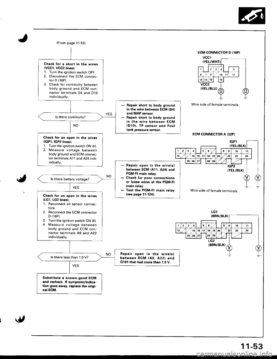
{From page 11 52)
Chock lor a shon in lhe wi.asiVCC1. VCC2lin$l:1. Turn the ignition switch OFF-2. Disconnect the ECM connec,tor D (16P).
3. Check lor continuity betweenbody ground and ECM con-nector terminals D4 and D10individually.
- Repair short to body groundin tho wire between ECM {D4land MAP 3enso..- Rep.ir short to body groundin the wire between ECMlD10l, TP sensor and Fueltank pa6ssure sanso..
Chock lor an op€n in the wire3{lGP1.lGP2lines):1. Turn the ignition switch ON (ll).2, Measure voltage betweenbody ground and ECM connec-torterminals A'11 and A24 indi-vadually.- R6pe;r open in the wire{slbetween ECM 1A11, A24l andPGM-FI main .elay.- Check for poor connectionsor loose wi.es at the PGM-FImain relay.- Test tho PGM-FI main ral.v(see page 11-124).Check for an open in the wires(LG1, LG2line3l:1. Reconnect all sensor connec-tors.2. Reconnect the ECM connectorD (16P).
3. Turn the ignition switch ON (ll).4- M easu re voltage betweenbody ground and ECM connector terminals A9 and A22individually.
Repai. open in the wir€ls)bctween ECM {A9, A22l .ndG101 ihet had more then 1.0 V.
ls there lessthan 1.0 V?
Substitute , known-good ECMand rechock. f symptom/indica-tion goes away, roplac6 the odgi-n3l ECM.
Wire side of female terminals
ECM CONNECTOR A I32P)
a,
Wire side of female terminals
LGl
1 1-53
Page 279 of 1680
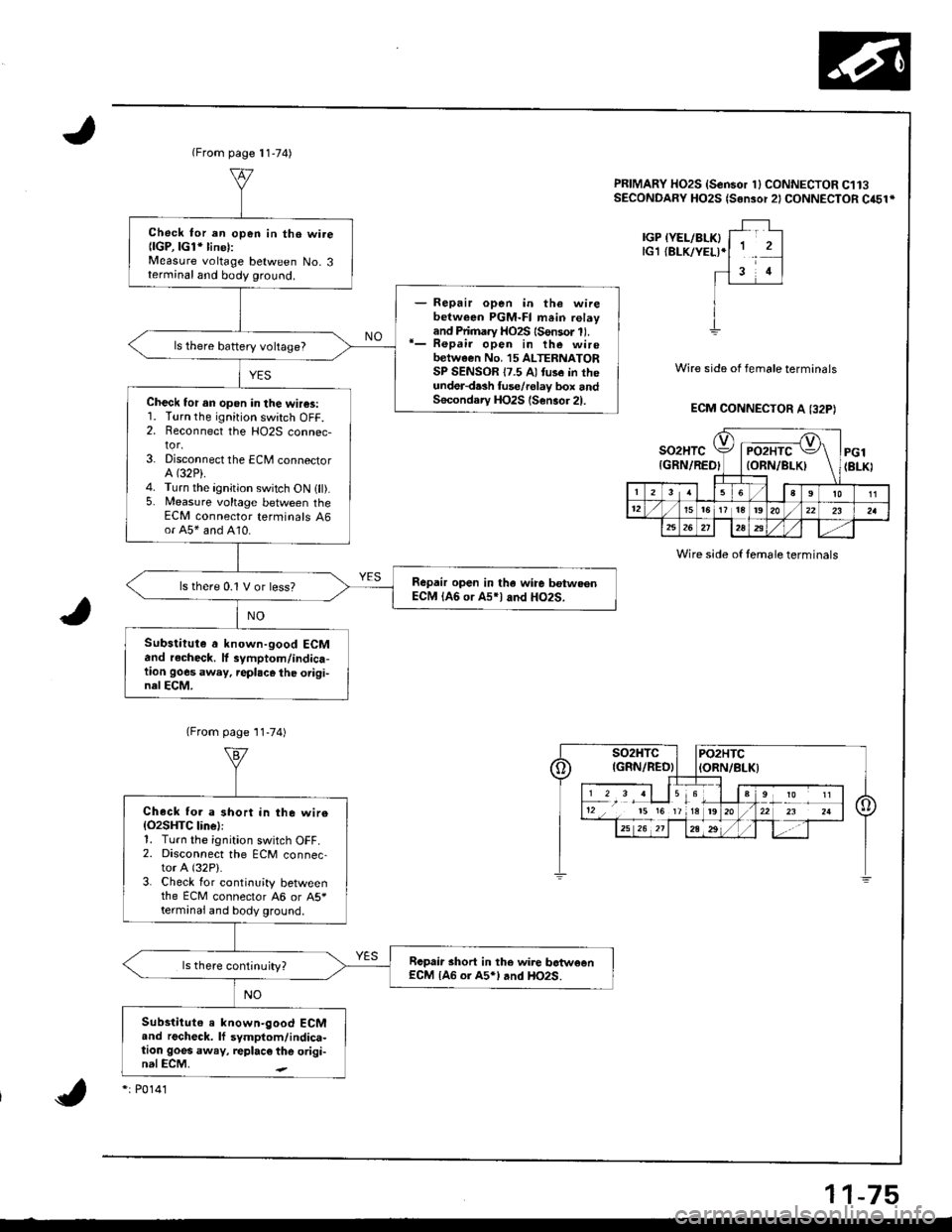
(From page 11-74)
Check tor an op6n in the wire{lGP, lGl* linel:Measure voltage between No. 3terminal and body ground.
Repair open in the wirebetween PGM-Fl mein relayand Pii.nary HO2S {Sonsor 11.Repair open in the wirebetween No. 15 ALTERNATORSP SENSOR 17.5 A) tuse in theund€r-d.sh fuse/rolav box andSecondary HO2S (S€n3or 21.
ls there battery vohage?
Check for an opon in the wh$:1. Turn the ignition switch OFF.2. Reconnect the HO2S connec-tor.3- Disconnect the ECM connectorA (32P).
4. Turn the ignition switch ON 1fl).5. Measure voltage between theECM connector terminals 46or A5* and A10.
Repair open in tha wire betw.enECM {A6 or A5rl and HO2S.ls there 0.1 V or less?
Substitute a known-good ECMand r.chcck. tf 3ymptom/indica-tion goes awey, repl.ce the odgi-nelECM.
PRIMARY HO2S {Sensor 1} CONNECTOR C113SECONDARY HO2S (Sensor 2ICONNECTOR C45tr
Wire side of female terminals
ECM CONNECTOR A I32P)
IGPlG1
so2HTC{GRN/RET
c
4tr
A, 4\'/ | PO2HTC \=/ \ltoRN/BLKt \-T--] \
PGl(BLK)
2a 1f lefil tt12't5t51? t8t92022 23
2526l2823
Wire side of temale terminals
(From page '11-74)
Check fo. a short in the wire(O2SHTC linel:1. Turn the ignition switch OFF.2. Disconnect the ECM connec-tor A (32P).
3. Check for continuity betweenthe ECM connector 46 or A5*termanai and body ground.
Rcpair short in the wire botweenECM IAG or A5*l .nd HO2S.ls there continuity?
Substituto a known-good ECMand recheck. lf symptom/indica-tion goes away, replac€ the origi-nalECM.
3 rl 15 6
15 15 17 lA
*r P0141
11-75
Page 292 of 1680
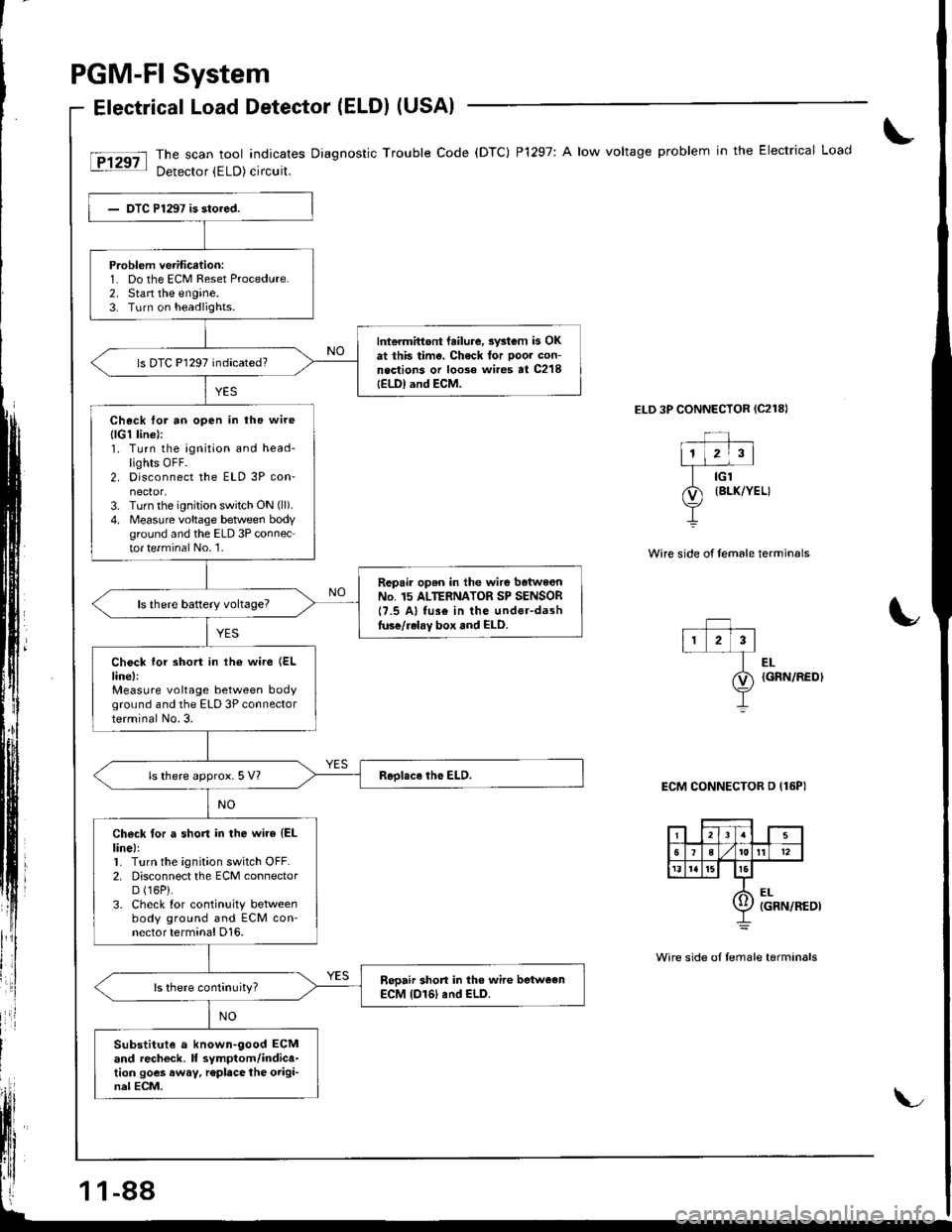
PGM-FI System
Electrical Load Detector (ELDI (USAI
The scan tool indicates Diagnostic Trouble Code (DTC) P1297: A low voltage problem in the Electrical Load
Detector (ELD) circuit.
ELD 3P CONNECTOR {C218)
Wire side of female termin€ls
Problem verification:1- Do the ECM Reset Procedure.2. Stan the engine.3. Turn on headlights.
Int€rmittont failure. swtom b OKat this time. Check tor poor con-neqtions or loose wi.es at C218IELDI and ECM-
ls DTC P1297 indicated?
Check for ao open in the wire
{lG1 linel:1. Turn the ignition and head-lights OFF.2. Disconnect the ELD 3P con-nector,3. Turn the ignition switch ON (ll).
4. Measure voltage betlveen bodyground and the ELD 3P connector te.minal No.'1.
Repair op6n in the wire baiwe€nNo. 15 ALTERNATOR SP SENSOR17.5 Al fus€ in the under-dashluse/relay box and ELD.
Chock lor short in the wire {ELline,:Measure voltage between bodyground and the ELD 3P connectorterminal No.3.
ls there approx. 5 Vl
Check for a short in the wire (EL
linel:1. Turn the ignition switch OFF.2. Disconnect the ECM connectorD (16P).
3. Check for continuity betweenbody ground and ECM con-nector terminal D16.
Sooair short in the wire betweenECM (D161 and ELD.
Substitut€ a known-9ood ECMand recheck. It symptom/indica-tion goes away, r€place the origi-nal ECM.
EL{GRN/REDI
ECM CONNECTOR D {16PI
Wire side oI Iemale tarminals
11-88
Page 300 of 1680
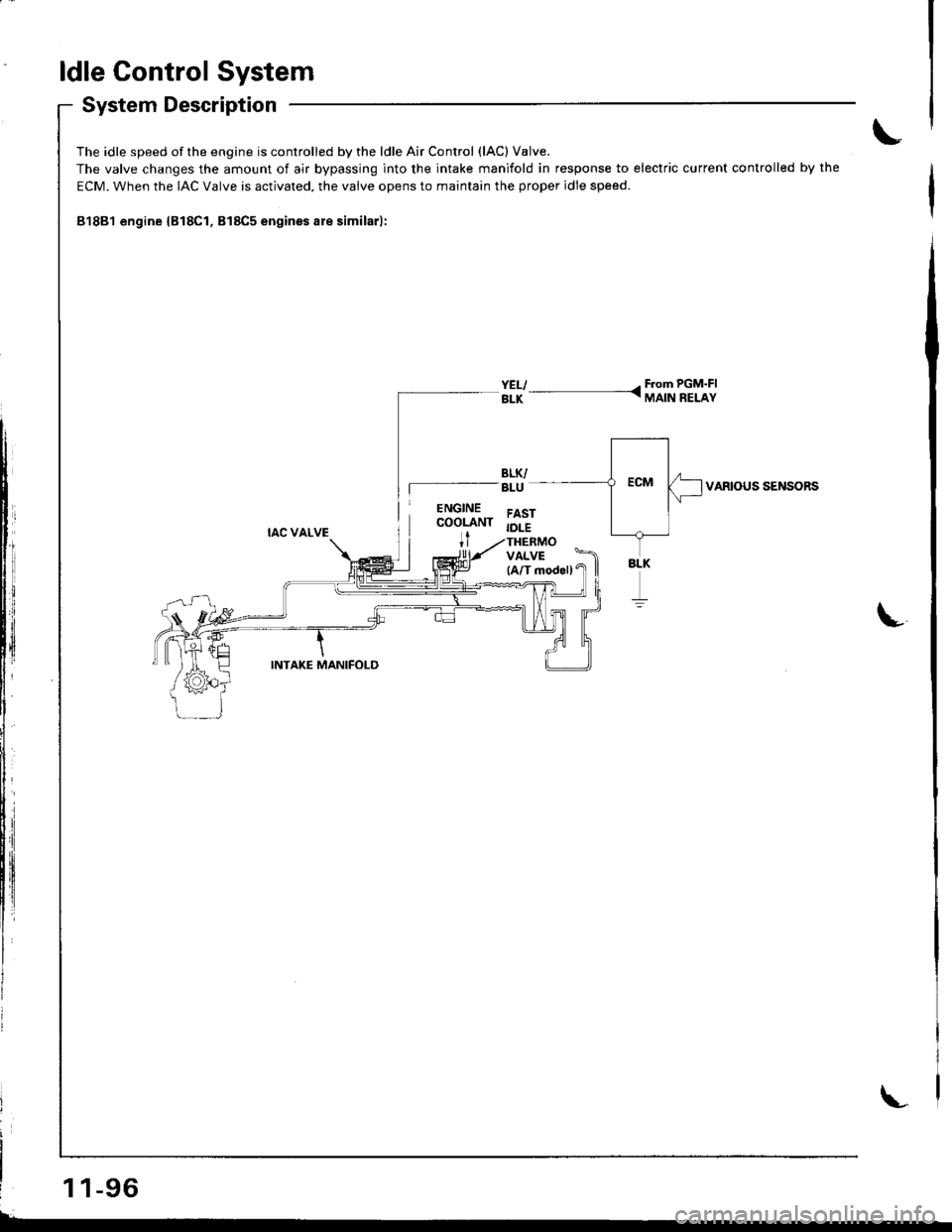
ldle Control System
System Description
The idle speed of the engine is controlled by the ldle Air Control (lAC) V8lve.
The valve changes the amount of air bypassing into the intake manifold in response to electric current controlled by the
ECM. When the IAC Valve is activated. the valve opens to maintain the proper idle speed.
81881 engine {B18Cl, B18C5 engines are similarl:
YELI - F.om PGM'FIBLK - MAIN RELAY
VARIOUS SENSORS
L
1 1-96