frame ACURA INTEGRA 1998 Service Owner's Manual
[x] Cancel search | Manufacturer: ACURA, Model Year: 1998, Model line: INTEGRA, Model: ACURA INTEGRA 1998Pages: 1680, PDF Size: 53.14 MB
Page 1043 of 1680

Evaporator
Replacement
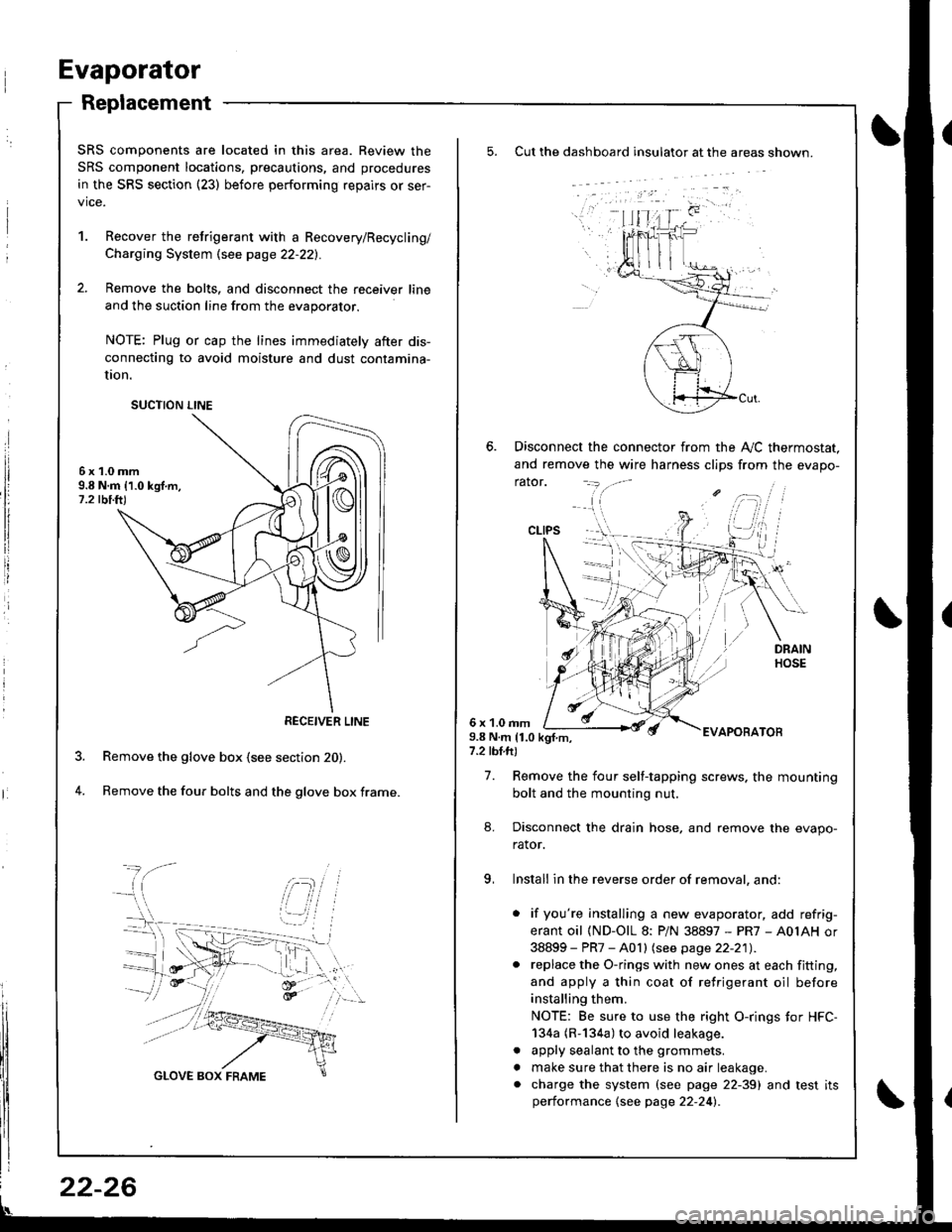
Cut the dashboard insulato. at the areas shown.
Disconnect the connector from the A,,/C thermostat.
and remove the wire harness clips from the evapo-
rator.
6 x 1.0 rnm9.8 N.m 11.0 kgf.m,7.2 tbl.ft)
EVAPOBATOB
7. Remove the four self-tapping screws. the mounting
bolt and the mounting nut.
8. Disconnect the drain hose, and remove the evapo-
rator.
9, Install in the reverse order of removal, and:
. if you're installing a new evaporator, add refrig-
erant oil (ND-OlL 8: PiN 38897 - PR7 - A0IAH or
38899 - PR7 - A0 I I lsee page 22-21) .. replace the O-rings with new ones at each fitting,
and apply a thin coat of refrigerant oil before
installing them.
NOTE: Be sure to use the right O-rings tor HFC-
134a (R-134a) to avoid leakage.
. apply sealant to the grommets.
. make sure that there is no air leakage.. charge the system (see page 22-39) and test itsperformance {see page 22-24l�.
CLIPS
SRS components are located in this area. Review the
SRS component locations, precautions, and procedures
in the SRS section {23) before performing repairs or ser-
vice.
1. Recover the retrigerant with a Recovery/Recycling/
Charging System \see page 22-221.
2. Remove the bolts, and disconnect the receiver line
and the suction line from the evaporator.
NOTE: Plug or cap the lines immediately after dis-
connecting to avoid moisture and dust contamina-
UOn.
6x1.0mm9.8 N.m 11.0 kgf.m,1.2 tbi.ft)
Remove the glove box (see section 20).
Remove the four bolts and the glove box frame.4.
SUCTION LINE
RECEIVER LINE
22-26
Page 1060 of 1680

Troubleshooting
Tips and Precautions (cont'd)
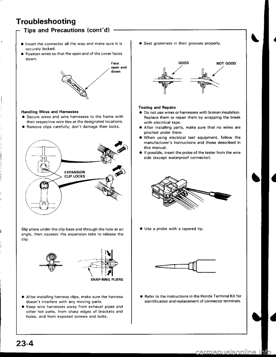
Insert the connector all the way and make sure it is
securely locked.
Position wires so that the open end of the cover faces
down.Faceopen end
V
Handling Wires and Harnesses
I Secure wires and wire harnesses to the frame with
their respective wire ties at the designated locations.
a Remove clips carefully; don't damage their locks.
Slip pliers under the clip base and through the hole at an
angle, then squeez€ the expansion tabs to release the
clro.
sNAP-R|NG PLtERS
After installing harness clips, make sure the harness
doesn't interlere with any moving parts.
Keep wire harnesses away from exhaust pipes and
other hot parts, trom sharp edges ol brackets and
holes, and from exposed screws and bolts.
GOOD NOT GOOD
MA/
lr lr\
Testing and Repairs
a Do not use wires or harnesses with broken insulation.
Replace them or repair them by wrapping the break
with electrical tape.
a Atter installing parts. make sure that no wires are
oinched under them.
a When using electrical test equipment. follow the
manulacturer's instructions and those described in
this manual.
a lI possible, insert the probe of the tester {rom the wire
side {except waterproot connector).
a Seat grommets in their grooves properly.
a Use a probe with a tapered tip.
Reler to the instructions in the Honda Terminal Kit for
identification and replacement oI connector terminals.
23-4
Page 1070 of 1680

Connector ldentification and Wire Harness Routing
Starter Cables
Connectol ot
Terminal
Numbel of
CavitiesLocationConnects toNotes
Tl
r2
Right side of engine compartment
Right side oI engine compartment
Under-hood Iuse/relay box
Starter motor
oBatteryBattery positive terminal
Battely Ground Cable
Connector ol
Terminal
Numbel of
CavitiesLocationConnects toNotes
Right lront shock towerBody ground, via battery ground
caore
oBatteryBattery negative terminal
Engine Ground Cable A
Connector ol
Terminal
Number ol
CavitiesLocationConnects toNotes
T3Left side of engineValve cover
c2Left side oI engine compartmentBody ground. via engine ground
Engine Ground Cable B
Connector ol
Terminal
Numbel of
CavitiesLocationConnects toNot€s
r4Right side of engine compartmentTransmission housing
Right side of front frameBody ground, via engine ground
wire B
A/C Wire Harness
Connector or
Terminal
Number of
CavitiesLocationConnects toNotos
c 151
cl54
c156
8
2,l
Righr side of engine compartment
Left side of engine companment
Left side of engine compartment
Left side of engine compartment
Main wire harness (C207)
A,/C pressure switch
Condenser fan motor
ly'C compressor clutch
Right side of front frame
Under-hood ABS Fuse/Relav Box Cable
Connector or
Telminal
Number of
CavitiesLocationConnects toNotes
T5Right side o'f engine compartmentUnderhood ABS fuse/relay box
@Right side oI engine compaftmentBattery positive terminal
23-14
Page 1226 of 1680

Headlight
Adjustment
Befole adiusting the headlights:
a Park the car on level ground.
a Make sure the fuel tank is full.
The driver or someone who weighs the same should
sit in the driver's seat.
Load the trunk with the items you usually carry (if you
usually pull a trailer, attach jt to the car).
Push down on the front and rear bumpers several
times to make sure the car is sitting normally.
When installing a new headlight assembly, tighten the
four mounting bolts so that the indicator in the verti-
cal gauge comes to the "O" mark.
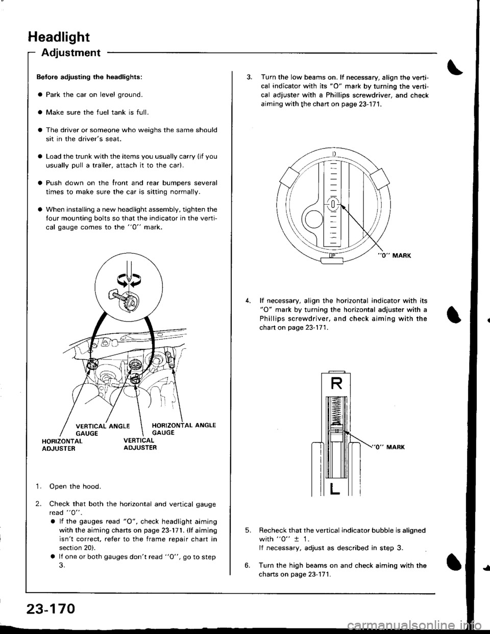
HORIZONTAL ANGLEGAUGE
HORIZONTALADJUSTER
'1. Open the hood.
2. Check that both the horizontal and vertical gauge
rcad "O" .
a lf the gauges tead "O", check headlight aiming
with the aiming charts on page 23-171. (lf aiming
isn't correct. refer to the frame repair chart in
section 20).
a lf one or both gauges don't read "O", go to step
23-170
3. Turn the low beams on. lf necessary, align the verti-
cal indicator with its "O" mark by turning the verti-
cal adjuster with a Phillips screwdriver, and check
aiming with the chan on page 23-171.
lf necessary, align the horizontal indicator with its"O" mark by turning the horizontal adjuster with a
Phillips screwdriver, and check aiming with the
chart on page 23-171.
5.Recheck that the vertical indicator bubble is aligned
with "0" t 1.
lf necessary, adjust as described in step 3.
Turn the high beams on and check aiming with the
charts on page 23-171.
Page 1392 of 1680

How To Use This Manual
Symbols
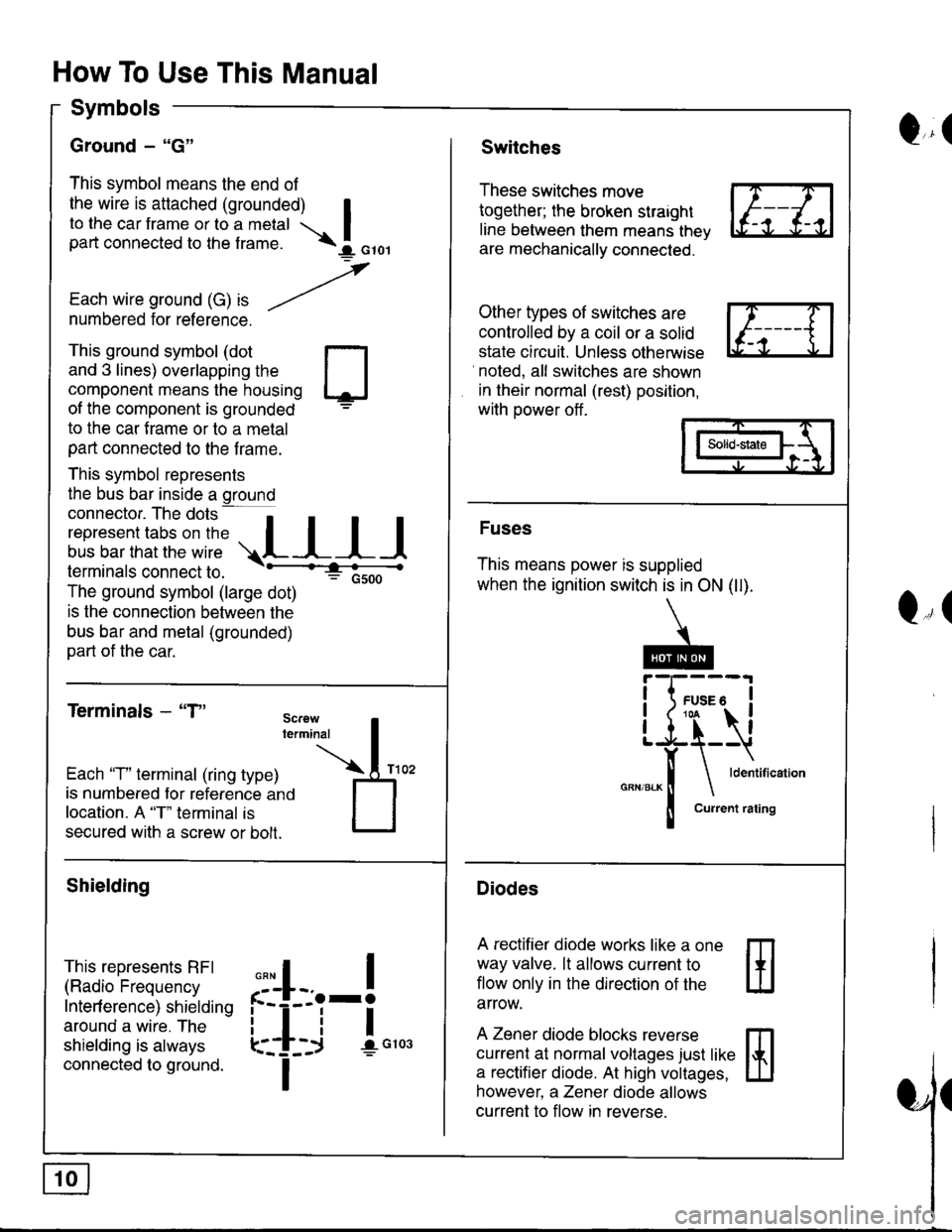
Ground - "G"
This symbol means the end of
the wire is attached (grounded) Ito the car frame or to a metal Ipart connected to the f rame. \I orol
,
Each wire ground (G) ," -/numbered for reference.
Q,(Switches
These switches move
together; the broken straight
line between them means thev
are mechanically connected.
Other types of switches are
controlled by a coil or a solid
state circuit. Unless otherwise
noted, all switches are shown
in their normal (rest) position,
with power off .
This ground symbol (dot
and 3 lines) overlapping the
component means the housing
of the component is grounded
to the car f rame or to a metal
part connected to the f rame.
This symbol represents
the bus bar inside a ground
connector. The dots a
i"r*"""*nn"l,':" .,.L I I I
lermtnals connectto. -'--'-:t"'--------<
The ground symbol (large dot)
: Gsoo
is the connection between the
bus bar and metal (grounded)
part of the car.
Terminals - "T"
m
ffi
Solid-state
Fuses
This means power is supplied
when the ignition switch is in ON (ll).
Diodes
A rectifier diode works like a one
way valve. lt allows current to
flow only in the dlrection of the
arrow.
A Zener diode blocks reverse
currenl at normal voltages just like
a rectifier diode. At high voltages,
however, a Zener diode allows
current to flow in reverse.
Q,(
Each 'T" terminal (ring type)
is numbered for reference ano
location. A "T" terminal is
secured with a screw or bolt.
Shielding
This represents RFI
(Radio Frequency
Interf erence) shielding
around a wire. The
shielding is always
connected to ground.
,,,
n
:'iL.-!
L-_+i !",*
I