relay ACURA INTEGRA 1998 Service Repair Manual
[x] Cancel search | Manufacturer: ACURA, Model Year: 1998, Model line: INTEGRA, Model: ACURA INTEGRA 1998Pages: 1680, PDF Size: 53.14 MB
Page 1547 of 1680
- How the Circuit Works
The immobilizer system is designed to prevent the
car f rom being started without the owner's ignition
key. lf an attempt is made to start the car without
the correct key, the immobilizer system will disable
the car's fuel supply.
The immobilizer system consists of the ignition key,
immobilizer receiver unit, immobilizer indicator
light, PGM-FI main relay, fuel pump, and the PCM
or ECM.
With the ignition switch in ON (ll) or START (lll), the
immobilizer receiver unit and the PCM or ECM
receive an "ignition on" signal through fuse 44 and
the PGM-FI main relay. The PCM or ECM then
sends power to the ignition key transponder through
the immobilizer receiver unit. The transponder then
sends a coded signal back to the PCM or ECM
through the receiver unit. lf the signal is correct, the
PCM or ECM will energize the car's fuel supply
system by grounding the PGM-FI main relay. The
immobilizer indicator light flashes a code to indicate
that the correct key has been inserted. lf the
ignition key signal is not correct, the PCM or ECM
will not energize the car's fuel supply system by not
grounding the PGM-Fl main relay. The immobilizer
indicator light then flashes a code to indicate that an
incorrect key has been inserted.
Refer to the Service Manual (Section 23,
Body Electrical) for specific tests and
troubleshooting procedures.
132-1
Page 1548 of 1680
Security System
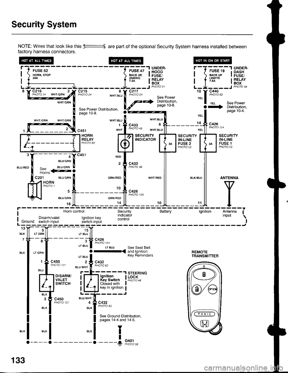
NOTE: Wires that look like this --::= are part of the optional Security System harness installed betlveen
factory harness connectors.
!-l-'*;;--
-----f.-u'?;l
HBB'J' !--T-'u-"-"-13X3"'*-| ) Ho-BN.srop ) B..l\-cj^qp I FUSE/ | ) Flg!!!p I FusE,| 1."^ | lTl"'", I RELAY I a ;'lx'" I RELAY| {--------------- l'* | Box I l -^ lBox
LJ--------.J4---------9----JP4oto21 L-Ja----JPHoro,3"\W27**^ -"hlT'jZn8:,*[:*ift :.1::t*'
seepowerpage 1o-8. a+ Distributjon,See Power Dislribulion. rZ)z----- I page 104.page 10-9.
''"' "t' 1.*"
*', "r:l-
- - - - - -,C **
, f]3,"0u, "1,f ";"3" *",J"11-------;'ff ;;;"
[F=]F;"#,.. kfl
t"ffBr+T'
EilHr{" E
mli
"."".:X-:-S]""'
"T['*-
ll ll
ffi'-"*FL_____r*F_*l
l^y^
c4s1 wnr I t"o'o 'o tn"r ".u | | ".. | | *n' ' '
i Horn control Security Battery lgnition Antenna Ia Horn control Security Battery lgnilion Antenna I
I Drsarm/varet rq indicator 'nPut \
: Ground switch input r.JllXi'lJ;,L control I! Ground switch input s'ivitcn inprlt IL------; ------Jtoy--T|f- -----,;]1
BrK ll rrGRNll LrBLU ll7 Yi- -;-lt- - - - - - -;-:t c426
"-l ,"":l :::lb.i[ri?n'a'fl:. r..rn?.,n| 'eru I Kev Reminders rRANsMlrrER
r
c4so z:L cqgz
:l-il*
",, I
ttu' . *'*'i'f, F;l'o"
rh d.,til i;-fr H{jfJ. I i{",;::*
Ed'"""" LliCir'l':i
":it*t*'
"t--,i[;""
I See Ground Distributron.I pages 14-4 and 14 5.
-.1
I
I
"..1
133
G401
Page 1551 of 1680
J
r-----T-
I r----T--"-==-1 lgnition
| | f--r i[!,iii[ir" lswncn
| | -/ Pase 10 lI I !'gcK < , sraRr I!!3"-.:^.*--1tli"' | |l l tf" p* l" | |I L----J!L----.1 |
T---------erxrwur It li9,o:,2",
M/r BLK wHr
I Nl
STEERINGLOCK
l
".--",f,
-ra
1r:I
10
BLKryI/HT
c413
A/T GEARPOSITIONswtTcHr..1STABTERcuTRELAY\,
ar., I
c413
JBLK/REO
11
l
".r".lt*'"totrba".s.::ri-,**
1 ^ C42ASECURITY
ffi P*tLt*%"*r*r"" I f--------
{ lsrnnren
l}l$!"i',:in'Hll;[* '.' n.1lt15*'
'"f--:
T[**,-- td:':i
! Ur,run:
"':ljl "T:'+-':- -r.sriqrF^
I """'-- rgA i I cros ai.i&li,
"."1 I i:T;li.p"d,El[ ii-";ls8iEl'J"i
l:j L"l:i'*'t- il--i it
1- c+ot L I
= PHero 56 (cont'd)
---a.
133-3
Page 1552 of 1680
Security System (cont'd)
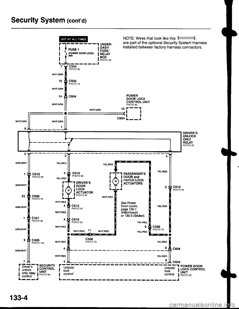
NOTE: Wires that look like this 5--------J
are part of the optional Security System Harness
WHT/GRN
6
r-l-------1 qrygER- l:Ii:"J u'e vPuv"q' vcvu"rv evole"' ' 'o
I I rus. t i P$38 installed between factory harness connectors'
! l s3*"0*"-* !83f"I I I aoros|LJ-------J, Y9,':A,,,rnr,o"n Iurs I csoe
I PHOfO 79
wnicnr I
r+ f, coor B38"tTo"*II CONTNOL UNITwHr GRN ll PHA|O 82
ll ,n",io"u 11i--l
ll--il-L__J
ll """o"n ll
A_______t_A
DRIVER'SUNLOCKONLYRELAYPHO|O 82
GFNAAIHT
GBNAVHT
GFNrI/VHT
GRNAiVHT
GRNAVHT
:4
;-[
@a
85
79
56
124ll n-o
l1
PASSENGER'SDOOR andHATCH LOCKACTUATORS
Seo PowerDoor Locks,page l3G1(Hatchback)or 1sGg (Sodan).
c610
VEL/BED
6
YEVREO
r ii.#:,:.'r sEcuRrw r;-_=----- ----=:-.r powER DooR
| ilril'ir- | fi$,ynol I unrucn/ l:nl@v I Lo.cK coNrRoL
| ::1ffi1"v l;;6ib" I contror controt liri6'ibazL---J L------- _____J
133-4
Page 1554 of 1680
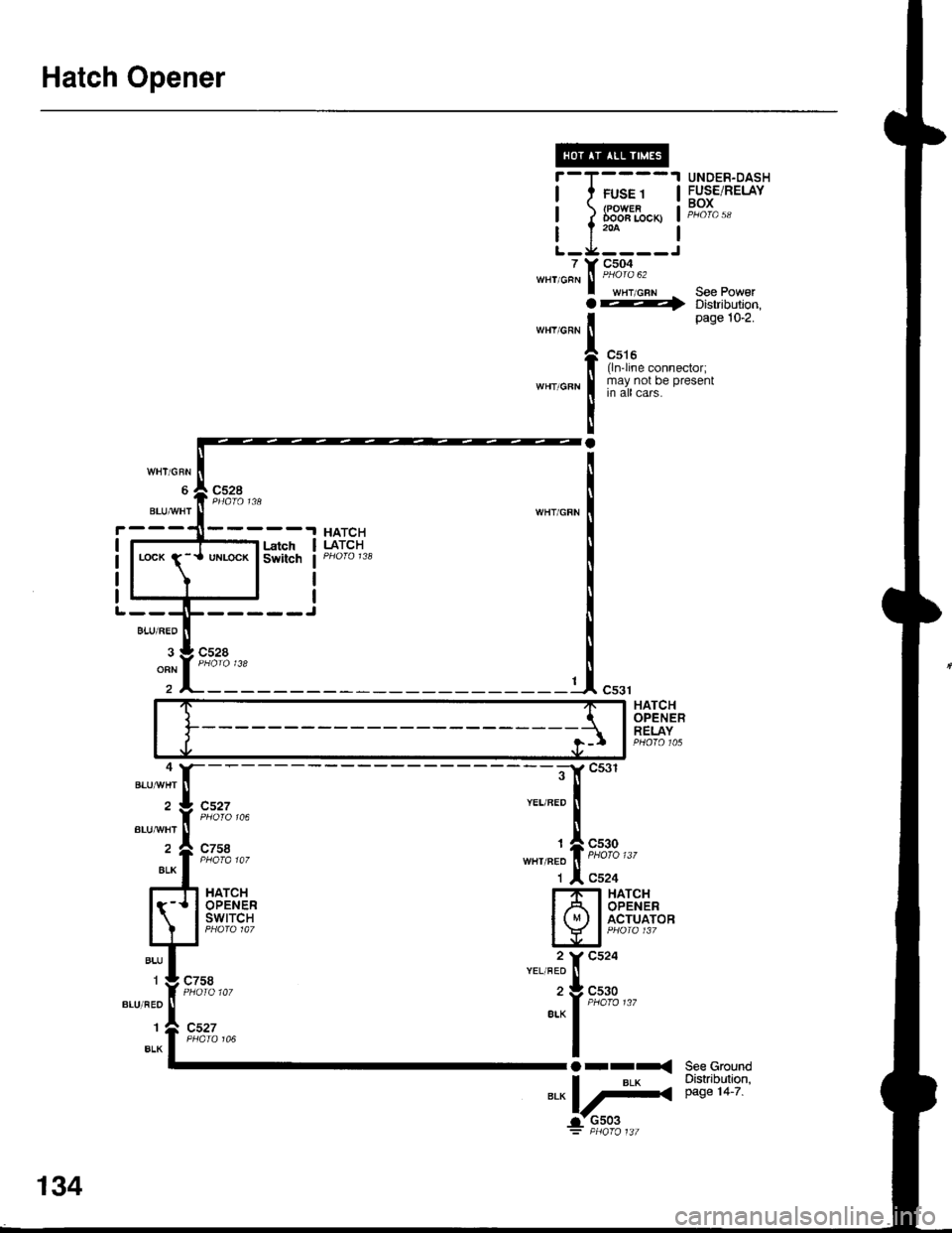
Hatch Opener
7WHT/GRN
WHY/GRN
;il
T(
t
IY
Ia
I
a
FUSE 1(POWERDooa Locx)
c504
wHT,cFN See Power---r> Distribution,page 10-2.
c516(ln'line connector;may not be presentin all cars.
UNDER-DASHFUSE/RELAYBOX
See GroundDistribution,page 14-7.
cs27
c758
c758
BLUAA/HT
cs30
c524HATCHOPENERswtTcH
HATCHOPENERACTUATOR
"":il;;,,,
Orr-<
*"L#
BLUAA/HT
134
Page 1555 of 1680
![ACURA INTEGRA 1998 Service Repair Manual lnterlock System
- 98-99 Models
l
HxPS*. !Til;;----
-i yxRi*I DASH I / rulE rz I HOOD
i[EiF,, i]!orn.o" Bli;;1il ilEjii
!s?T"., Lt::-s::3L j "3T",,. P,vu,d Lg _ _ Lt av ^rra: 8Y C216 16I wx ACURA INTEGRA 1998 Service Repair Manual lnterlock System
- 98-99 Models
l
HxPS*. !Til;;----
-i yxRi*I DASH I / rulE rz I HOOD
i[EiF,, i]!orn.o" Bli;;1il ilEjii
!s?T"., Lt::-s::3L j "3T",,. P,vu,d Lg _ _ Lt av ^rra: 8Y C216 16I wx](/img/32/56983/w960_56983-1554.png)
lnterlock System
- '98-'99 Models
'l
HxPS*. !'Til;;----
-''i yxRi*I DASH I / rulE rz I HOOD
i[EiF,, i]!orn.'o" Bli;;1il ilEjii
!s?T"., Lt::-s::3L j "'3T",,. P,v'u,d Lg _ _ Lt av ^rra: 8Y C216 16I wxlcnr,r PHora 24
J!^_YEUBLI
UNOER.OASHFUSE/RELAYBOX
c440
c432
ll S€o Power Diskibution,I page 10-9.
,n"tto"" I
1c,u'"" 11 | sa31F-I''I BRAKE SWITCH T--1 THROTTLE
I I closed wrth brake | 5"ns6, I lg.qLrlgN fiP)
lq-]J 1"""",i:;*""* t iii*' i "s'H39*
:ilH1fti$;",,"
;lX *Tt r#i*f= ft;1uii,'" 11? I ;:: [S[l 5p,[,"f*,,*""*l
;ny,t;sfl E?[T
l-T;l'"
t, L- t''""t'1"' ---C "0.,, to"-t' I
STEEBINGLOCK
r-=KeyInlerlockSwitchClosed withkey pushsd.
KeylnterlockSolenold
'" I--j"$t'U"t--:t "o', 3*".''
'f 'o"
i
-
r-, gEr-
- - -;;; - - - -: t rmrsu tsstot't ll
L$'e: 1ui ifiin?rri!::::
I
:- - _ _ _ _::{ : _ _ _ _ _ _ __ - - - J "",.
-JWHT]"TEL
INTERLOCKCONTROLUNIT
;,-".t^-l[-
-------;;f[ ":'"'"."'
seeA/rGearr A c+sg ar< Posnon
wHr BL( [ ero'o i28 cn1,,rvxr ll Indicalor
r* "o"* rz | g+r.q -,
l,/ |Bi*:yJL,tx o"nf'$y:-----1a"r.EAR
I G-11 sh,ft rever push ! | "- i a.o, I P/,oSlTloN swlTcH
-il,tii,oJ,tu"o.""""0 | ^ll \, | -'
-iJcni.'
!"L-----. i, !
'g",J"T,F;:'A$l"Y"";%,r, i" ---1 'r a solenord flom enelgrTing
"'^l '";;'"-
R:":.Rt?i# i F 33""'?Ji"" i ::f;',3J3u:"00":"":Ji",",",a-< 3l'Jlilgl L___+_::':_j ;;ff;;;;rr"p,".."dBLK I NOTE: In case olBLK I NOTE: In case ot syslem
Y r ! ccro malfunchon lhesh1fllever
I ",, I paoro to can be released byI --' I oushino the ionition kev
J---r"?r-"*l-f----) Distribution,
I oaoe to-o.
I ruse aa flNTERLocK uNrn( r.5^
i.- - ---- -
Koy Int6rlockCircuitAllows key inlerlocksolenoid to boenergized unlessshift lever is in "P'
138
f __ --__l pushing lhe ignition key
,lt--- il'""J1:oi:'""i,:"0'"d'l-' c4ol
Page 1556 of 1680
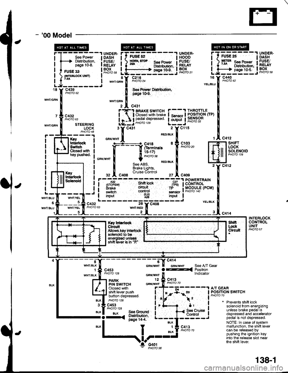
- '00 Model
I
I
FUsg 52I56€ Pow€r Ilxrtdhxbn, :g9:t"t:.i
UNDER.HOODFUSEiRELAYBOXPHOfO 21
Sse Power I DASHDlslribution, : FUSE/page 1G8. I RELAY
c440
c432
WHT/GFNSTEERINGLOCK
rry Ihtsdock :Suhch IClos€d with Il(ey pusned. I
I
I
I
I
I
I
c432
It
I
I
l-
WrtT/BLU
WHT/BLU
KryIr$rdockSdanold
c412-l SHIFT
, I LOCKI I SOLENOIDI lcuoto tzo
Jc412
c414
rAc4
m2Y c4
INtl
.-, I
i/BLX U
-rl"o
POWERTRAINCONTROLMODULE(PCM)
YEVBLX
INTERLOCKCONTROLUNIT
"-*;.'l[-
- - - - - - - -;*f-tr "'"'"'"-,,
r I casr a4
""""#"J;:.
_^ ll"ij*sa*,"
l4J $l't'"ii,''F:^,
*"T't. 3il1;'
;fi;ifJ,t""**o
i"'f- .
*1'
S€e A,/T GsarPositionlndicator
"liiffo,,' a"-BLK I 506 Grourd I-i-. ;*'o' ---;
*"1
I "l! s'*l'"-
Prevents shift locksolenoid trom energizingunless brake pedal isdepressed and acceleratorpedal is not depressed.
NOTE| In case of systemmalfunction, the shilt levercan be released bypushing the ignition keyinto the release slot nearthe shift lever
$l;---l UiSi'"
BRAKE SWITCH F--.t THROTTLE
;'3i:g*s::: !.mnj iffibr-
*,
,V-I'c4ol: PHoro s6
138-1
Page 1558 of 1680
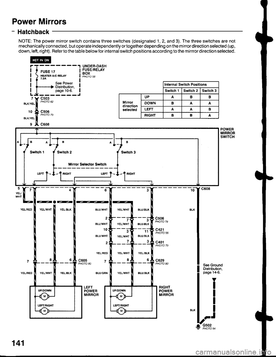
Power Mirrors
- Hatchback
NOTE: The power mirror switch contains three switches (designated 1, 2, and 3). The three switches are not
mechanically connected, but operate independently ortogether depending on the mirror direction selected (up,
down,left, right). Refertothetable belowfor internalswitch positions according to the mirrror direction selected.
@
I I ruse rz I
I xearenrceeuv I
|{754 |I I Uee FOI/ver I! l-----.-.| Distribution. !I I pase 10-6. ILg-------J
UNDER.DASHFUSE/RELAYBOX
7 ll, Cs03
"'-^."..
|
"'otou'
'o ft ffi%,,erxner II x c608
Internal Switch Positlons
Switch 'lSwltch 2Switch 3
Mirordirectionselected
UPAB
oowNA
LEFTAAE
RIGHTBA
B
Swiich 3
Mirror Ssl3clor Switch
LEFT } - I.1 RIGIfI
POWERMIRRORswtTcH
BLU/'WHT
BLU]'IVHI
10
BLU^^/HT
YEL/REO
7
ALU/GRN
YEL/YVHTBLU/ALK
11BLU/BLK
cs06
7
YEL,ryvHTPHOTO 56
c401
c629PHO|O A0c605PHOTA 80
141
Page 1561 of 1680
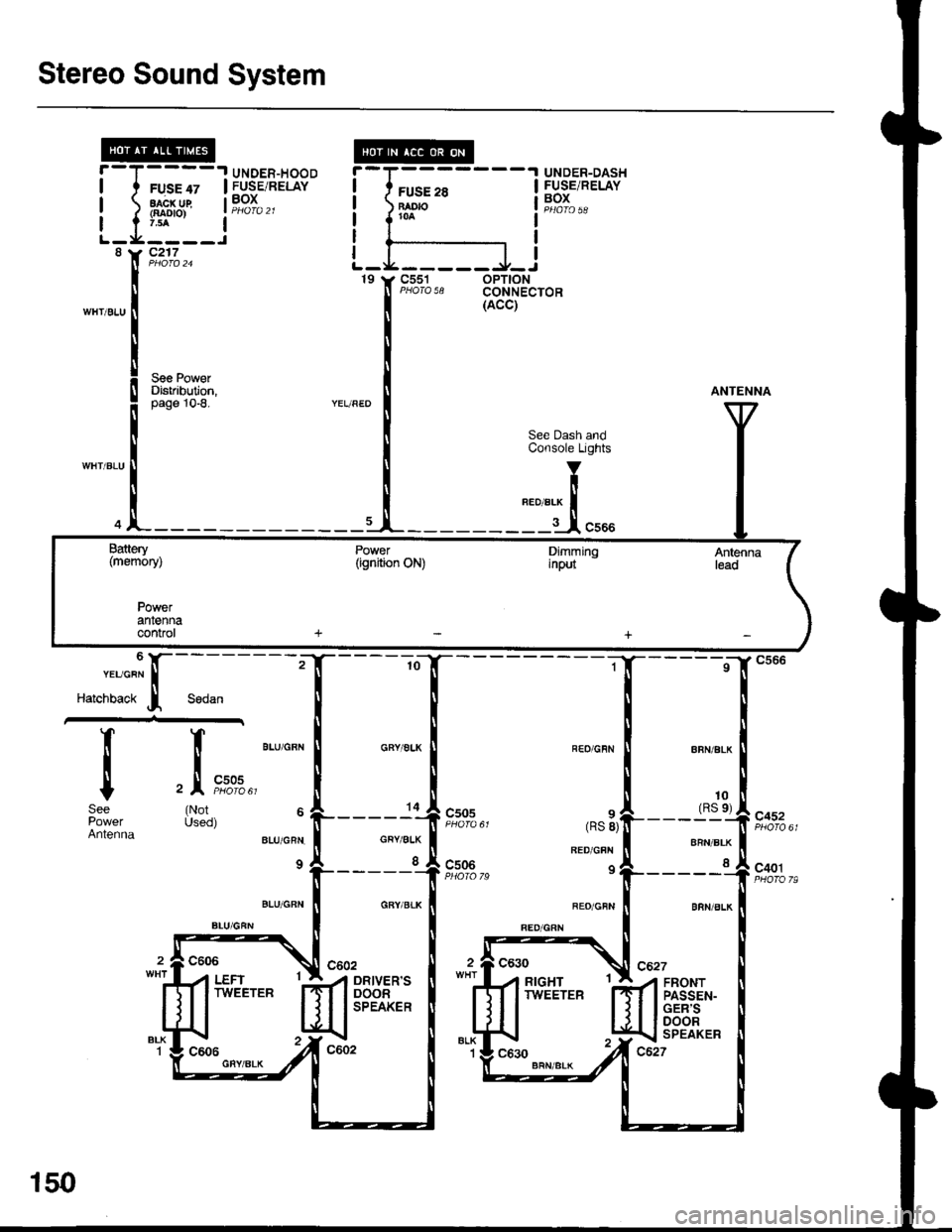
Stereo Sound System
UNDER-HOOD.I UNDER-DASH
I FUSE/RELAYI
I
I
-T',
?j-v,-
:I
rl
I
I
I
8
WH'/BLU
FUSE 28BAO|()roa
L_L____l_J
FUSE 47FUSE/RELAYBOXaacx ug{aao|o)
c217
c551 oPT|ONPHOTA 58 CONNECTOR19 t, C551
See PgwerDistribution,10-8.
10(RS e)
c505
Sodan
It
Itc
(NotUsed)
6 l,-"."'c"" I
Harcnoact j
T_
i
tSee
AntennaCRY/ALK
I
csos
c506
8RN/BLK
I
c452
c401
FRONTPASSEN-GER'SDOORSPEAKER
Battery(memory)
Powerantennaconrol
150
Page 1563 of 1680
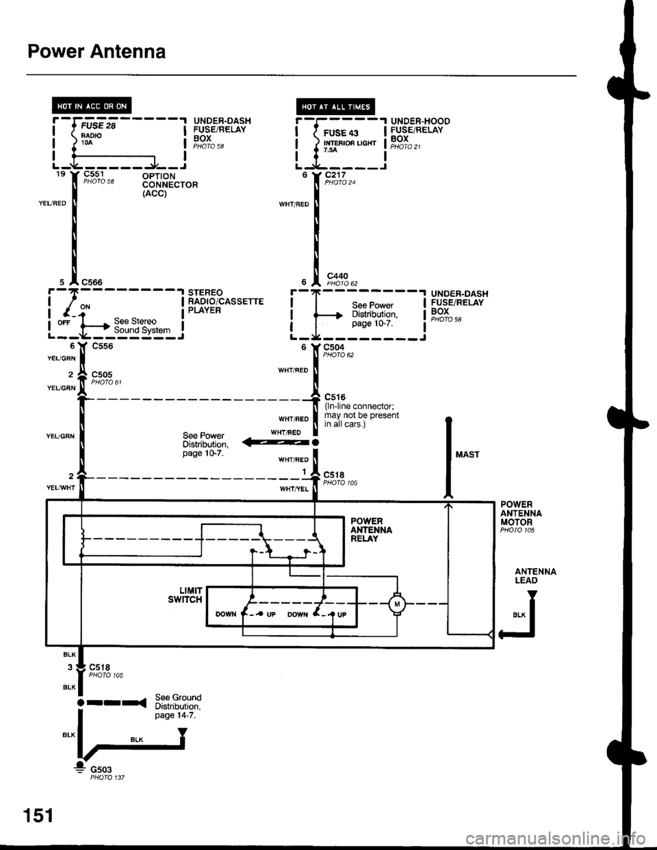
Power Antenna
9_5^s,1 -^ oPloNCONNECTOR(ACC)
c505
UNDER.DASHFUSE/RELAYBOXPHOTO 58
ifsEii'-----'1NAD'O
UNDER-DASHFUSEiRELAYBOXPHOTA 58
STEREORADIO/CASSETTEPLAYER
UNDER-HOODFUSE/RELAYBOX
T--;;--+--{> Distribution,
I__i1':__
f
r*.,
I"."
I
I
I
YEUGBN
2
YEUGFN
l"^"
@.
WHT/BEO
1c5tI
POWERANTENNAMOTOR
ANTENNALEAO
er* I
FJ
c518
See GroundDistribution,page 14-7.
iT;;-r
L-tr:-::i6 Y C217
s A c566
i-I*-------t
I r-i- |
LI-t.-*-3E&"{3::J
151
arrxa