Engine ACURA INTEGRA 1998 Service Repair Manual
[x] Cancel search | Manufacturer: ACURA, Model Year: 1998, Model line: INTEGRA, Model: ACURA INTEGRA 1998Pages: 1680, PDF Size: 53.14 MB
Page 1499 of 1680
Gauges (cont'd)
- How the Circuit Works
When the ignition switch is in ON (ll) or START (lll),
battery voltage is supplied through fuse 25 to the
gauges in the gauge assembly.
Speedometer and Odometer
The odometer and speedometer drive circuits
receive pulses lrom the vehicle speed sensor
(VSS). The pulse rate increases as the car
accelerates. The frequency and duration of these
input pulses are measured and displayed by the
speedometer, odometer and tripmeter.
Tachometer ('98-'99 Models)
The tachometer drive circuit receives oulses from
the ignition control module (lCM) in the distributor
assembly. The solid-state tachometer then displays
these pulses as engine speed. For each 200 pulses
per minute from the ignition control module (lCM),
the tachometer displays 100 RPM.
Tachometer ('00 Model)
The tachometer drive circuit receives pulses f rom
the PCM or ECM. The solid-state tachometer then
displays these pulses as engine speed. For each
200 oulses oer minute trom the PCM or ECM the
tachometer displays 1 00 RPM.
Engine Coolant Temperature Gauge and Fuel
Gauge
The engine coolant temperature gauge has two
intersecting coils wound around a permanent
magnet rotor. Voltage applied to the coils, through
fuse 25, generates a magnetic field. The magnetic
field, controlled by the engine coolant temperature
gauge sending unit, causes the rotor to rotate and
the gauge needle to move. As the resistance in the
sending unit varies, current through the gauge coils
changes. The gauge needle moves toward the coil
with the strongest magnetic tield. The fuel gauge
works the same way.
The engine coolant temperature gauge sending
unit's resistance varies from about 137 ohms at low
engine temperature to between 30-46 ohms at high
temperature (radiator fan running).
The fuel gauge sending unit's resistance varies from
about 2-5 ohms at full, to about 110 ohms at empty.
When you turn the ignition switch to LOCK (0), the
gauge remains at the last reading until you turn lhe
ignition switch to ON (ll) or START (lll) again.
Refer to the Service Manual (Section 23, Electrical)
for specific tests or troubleshooting procedures.
81'2
Page 1546 of 1680
lmmobilizer System ('00 Model)
POWERTRAINol ENGINECONTROL;,6ri iriE' !- - - - -F^-E; -
I 1,'r._,..--:
-'j
!.i3!.* i f ;.-. *-
- -
F ;; ; I H 3BB"(Pclvl or EcM) I ( rri-*." ",ono. rua ruur lsns urrll Firser i o_e,n xrano I FUsEi
ig-r i fl^.ee,ntesra,ed fi;rl,u,:l i iEioi i f
"'-
l
'*"
iEEf'
! :"'ll,l' ! L---g-_'ry_+J-:_E.:gil
"u'*
il.^=---=I-= -i;;eo'�'
io"-r, I B:i,fffil
!4.1ry.. : pase lo-e.RELAY
WHI/GRN
;{---------61'c446 t
i ;;6;;;uno o'"u'u"'on l I GAuGE
""i;i ,.""..1
i*':,:""#'= PHoro2s
| ! (9 ilSi'"ito" I
yffi
i"Yffi i
| ,""o",.,r.*
-'-=--l t;ia;;----'
I "ffi;f:'- ,.!, "ouu ""- I
"..".* i I
I I l"#fl;llF#'*"
, ffi ".,, ILF"l'�
"."
; I "..,
7;:F,
-;:*+
,-�Tr,u-,"*"tilt, f I [-;*tn-
-l
isx,fi^'no"
ul.:ii'o codeinput enabre
I iilfli:lT*, itf$Egf(LGr)-J | 2------J (PCM or20
tr,
c4s7
| :,"#,.,enr erx | ! s." crouna
t g"-:,Bn'*,l l
guW
"""".-U:i' BFN""l--i
i:-f,:g:,, Yffi:
".,"":r------*-";T
^
| ,"!::.," !
-:":fr'*,,
I
[f,"i;. I
".--rr
l N
'lr**"" ,,tr*,
I
i--!r,
*.**il
iltlw
IJ: PHafag4
132
Page 1553 of 1680
- How the Circuit Works
The security system control unit has a 3 position
switch: Manual. Auto. and Auto Lock. Here's what
happens when you arm the system, regardless ol
the switch position:
o The parking lights will flash once.
. The security indicator will flash once per second
after the system is armed.
With the switch in the Manual position, the security
system can only be armed by using the remote
control transmitter, After you remove the key from
the ignition and close all doors, the hood (if
equipped with the optional hood switch), the hatch
or trunk. Dress the lock button on the transmitter
and the system will arm (if the system is in the beep
sound mode, the horn will sound once). The doors
will automatically lock when the system is armed.
With the switch in the Auto position, the security
system will arm itself within about 20 seconds after
you turn the engine off, remove the key from the
ignition, and close the halch or trunk, the hood (if
equipped with the optional hood switch), or last
door. lf a door is opened during the 2o-second exit
delay time, the timer will reset itself . The remote
control transmitler can still be used to arm the
system with the switch in Auto position (see manual
for details).
With the switch in Auto Lock position, the security
system will arm itself and lock the doors about 20
seconds after you turn the engine of{, remove the
key from the ignition, and close the hatch or trunk,
the hood (if equipped with the optional hood
switch), or last door. lf a door is opened during the
2o-second exit delay time, the timer will reset. The
remote control transmitter can still be used to arm
the system in the Auto Lock position.
Triggering the Alarm
After the security system is armed, the sound ot
breaking glass or the opening of a door, hood,
hatch or trunk will trigger the alarm, and cause
the following:
r The horn will sound for30 seconds.
The optional siren will sound lor 60 seconds.
. The parking lights will flash.
. The security indicator LED will flash twice per
second.
. The starter will be disabled.
At the end of the alarm cycle, the system will
automatically rearm.
Disarming the Security System
There are two ways to disarm the security system:
. With the transmitter
o With the disarm/valet switch
When the system is disarmed, regardless of the
method used, the parking lights will flash two times if
the alarm has not been triggered and three times if
the alarm has been triggered. To disarm the system
with the transmitter, press the unlock button (if the
system is in the beep sound mode, the horn will
sound two times if the alarm has not been triggered,
however, will sound three times if the alarm has
been triggered). The driver's door will unlock
(pressing the unlock button twice will unlock all
doors).
To disarm the security system using the
disarm/valet switch, enter the car and turn the
ignition switch to ON (ll) then press the disarm/valet
switch button. lf you open the door when the control
unit switch is in Auto or Auto Lock, a 2o-second
entry delay will give you time to disarm the system.
However, when the system is armed by the
transmitter, the entry delay time is changed to zero
seconds, and the alarm is triggered as soon as you
oDen the door.
ldentifying Tripped Sensors
The system will indicate the sensor which triggered
the alarm through the security indicator LED. While
sitting inside the vehicle wlth the key out of the
ignition switch, all doors, the hood (if equipped with
the optional hood swilch), the hatch or trunk must be
closed. Press and hold the disarm/valet switch.
Press the lock button and then the unlock button of
the transmitter. Belease the disarm/valet switch. The
status LED will blink according to the following code:
Sensors
Door
Trunk/Hatch
System Switches
Glass Breakage
Hood (Optional)
Number ol Flashes
1 blink, pause, repeat
2 blinks, pause, repeat
3 blinks, pause, repeat
4 blinks, pause, repeat
5 blinks, pause, repeat
For further operating instructions and troubleshooting,
see the security system owner's manual.
133-5
Page 1566 of 1680
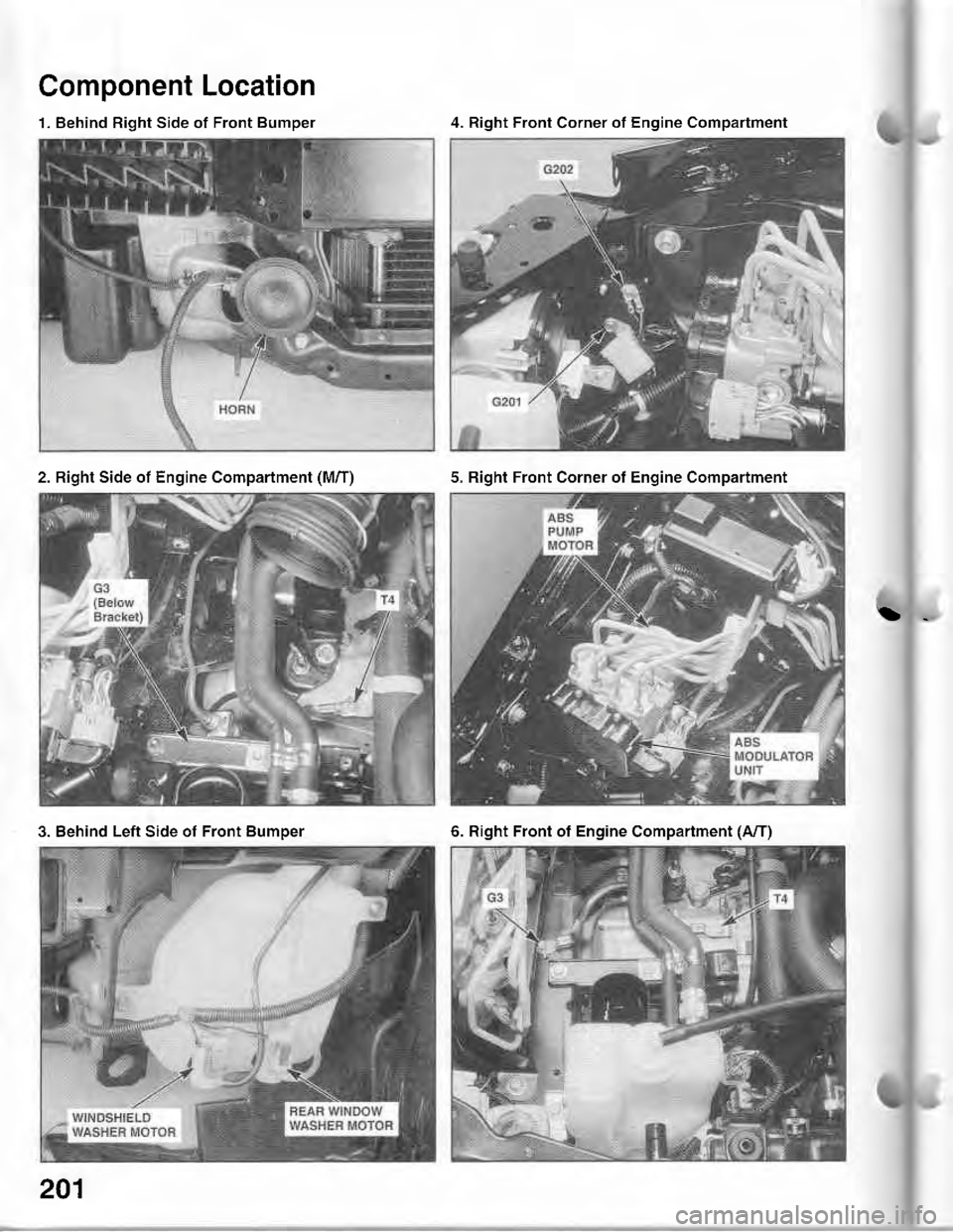
Component Location
1. Behind Right Side of Front Bumper4. Right Front Corner of Engine Compartment
2. Right Side of Engine Compartment (M/T)5. Right Front Corner of Engine Compartment
3. Behind Left Side of Front Bumper6. Right Front of Engine Compartment (A/T)
201
Page 1567 of 1680
)_
)*
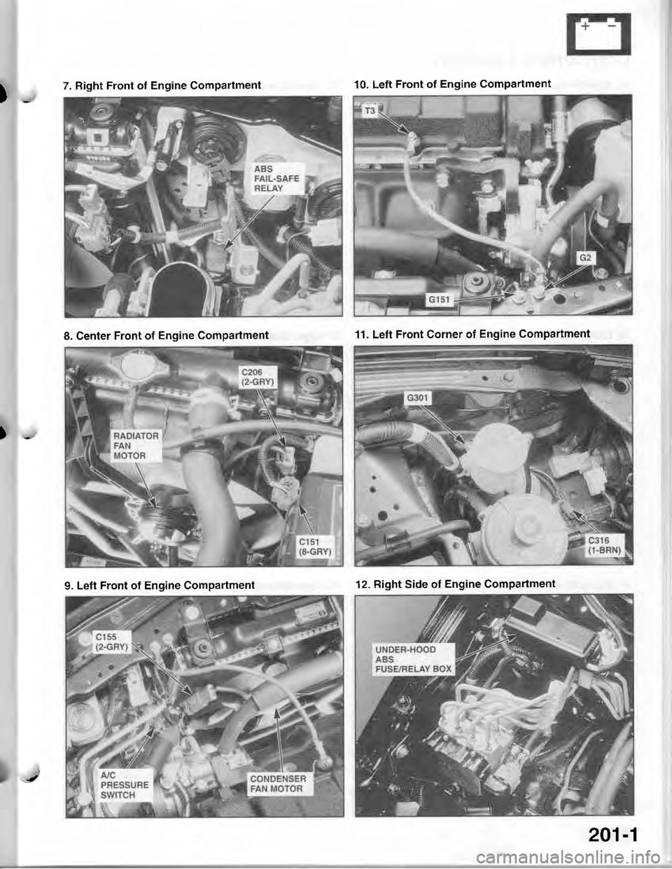
7. Right Front ot Engine Compartment10. Left Front of Engine Compartment
8. Center Front of Engine Compartment11. Left Front Corner of Engine Compartment
9. Left Front of Engine Compartment12. Right Side of Engine Compartment
201-1
Page 1568 of 1680
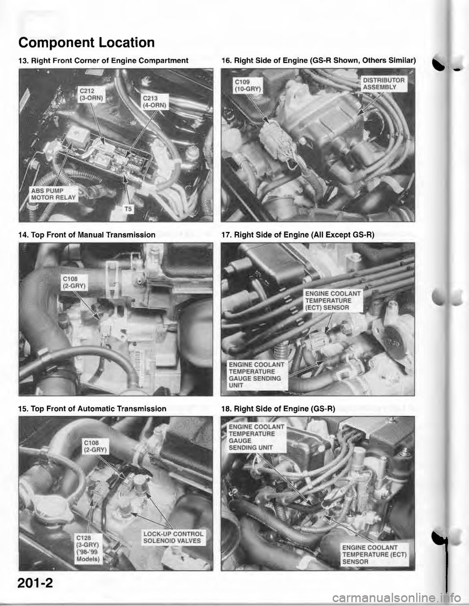
Component Location
b-
13. Right Front Corner of Engine Compartment16. Right Side of Engine (GS-R Shown, Others Similar)
14. Top Front of Manual Transmission17. Right Side of Engine (All Except GS-R)
15, Top Front ot Automatic Transmission18. Right Side of Engine (GS-R)
l201-2
Page 1569 of 1680
)-
)-
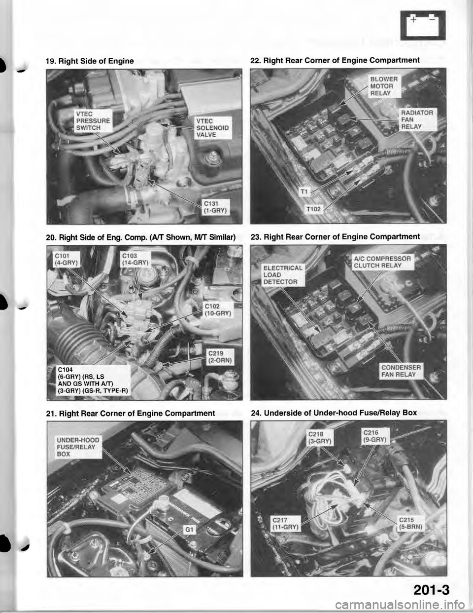
19. Right Side of Engine22. Right Hear Corner of Engine Compartment
20. Right Side of Eng. Comp. (A/I Shown, lvVT Similar)
c104(6-GRY) (RS, LSAND GS WITH A,IT)(3-GRY) (GS-R, TYPE-F)
23. Right Rear Corner of Engine Compartment
21. Right Rear Corner of Engine Compartment24. Underside ot Under-hood Fuse/Relay Box
l.
201-3
Page 1570 of 1680
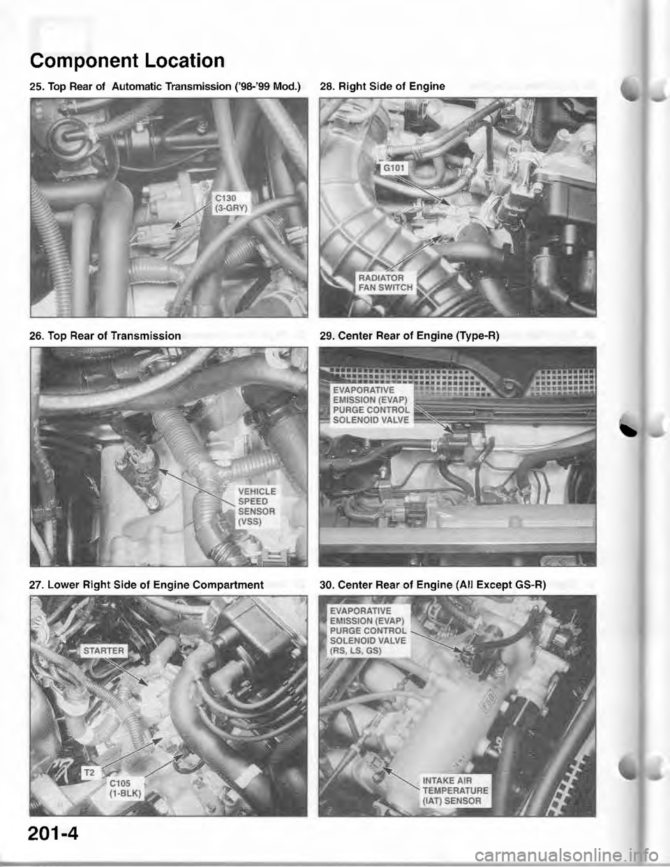
25. Top Rear of Automatic Transmission ('98-'99 Mod.)
Component Location
\
28. Right Side of Engine
26. Too Rear ot Transmission29. Center Rear of Engine (Type-R)
27 . Lower Right Side of Engine Compartment30. Center Rear of Engine (All Except GS-R)
201-4
Page 1571 of 1680
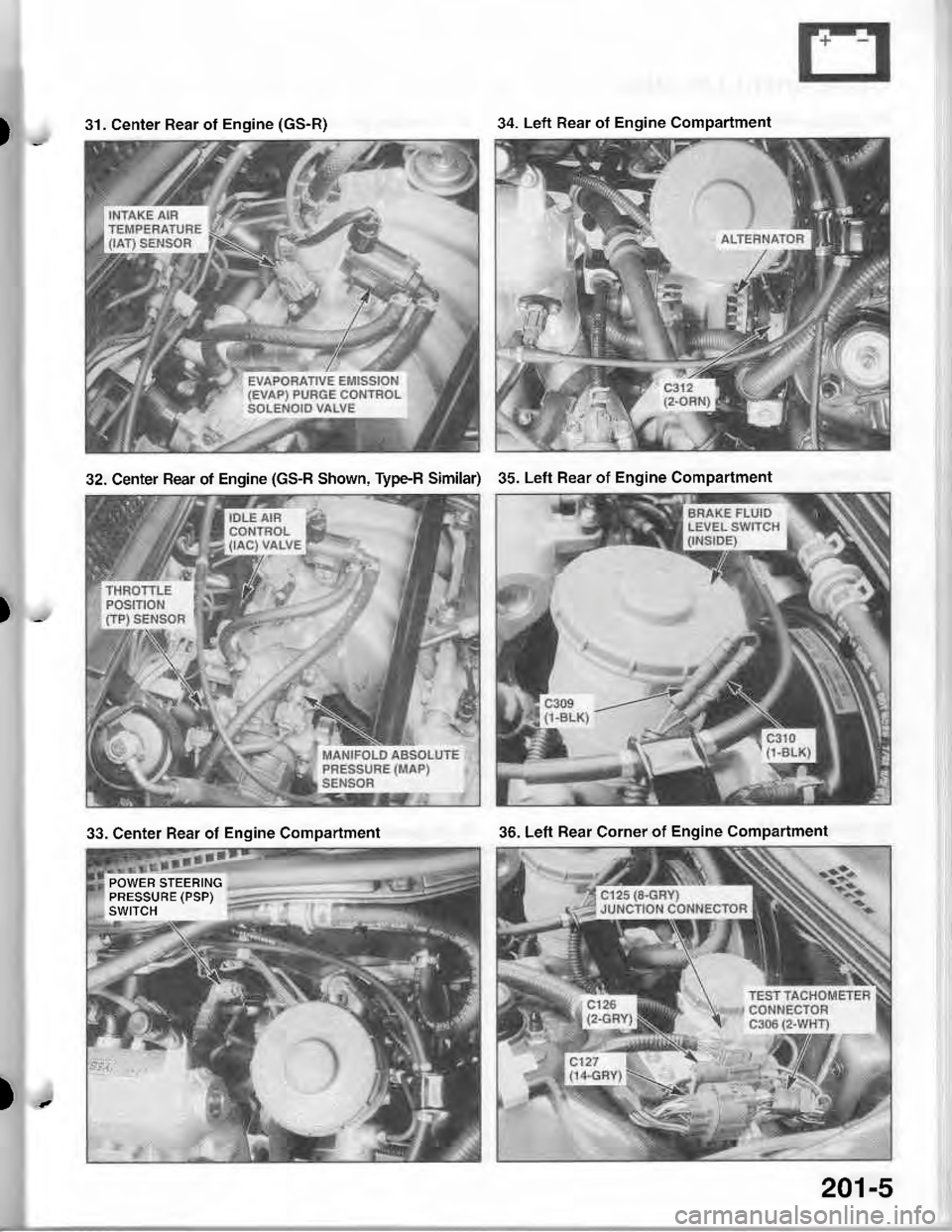
)_
)_
)-
31. Center Rear of Engine (GS-R)34. Left Rear ot Engine Compartment
32. Center Rear ot Engine (GS-B Shown, Type-H Similar)35. Left Rear of Engine Compartment
33. Center Rear of Engine Compartment
POWER STEERINGPRESSUBE (PSP)SWITCH
36. Left Bear Corner of Engine Compartment
201-5
Page 1572 of 1680
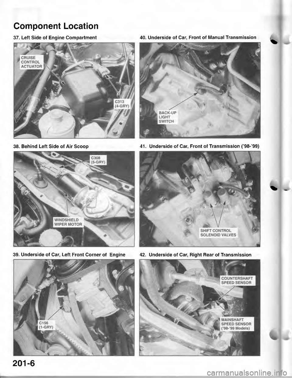
37. Left Side of Engine Compartment
Component Location
!
42. Underside of Car. Bight Bear ot Transmission
40. Underside of Car. Front of Manual Transmission
38. Behind Left Side of Air Scooo41. Underside of Car, Front of Transmission ('98-'99)
39. Underside of Car, Left Front Corner of Engine
201-6