Cooling fan ACURA INTEGRA 1998 Service Repair Manual
[x] Cancel search | Manufacturer: ACURA, Model Year: 1998, Model line: INTEGRA, Model: ACURA INTEGRA 1998Pages: 1680, PDF Size: 53.14 MB
Page 195 of 1680
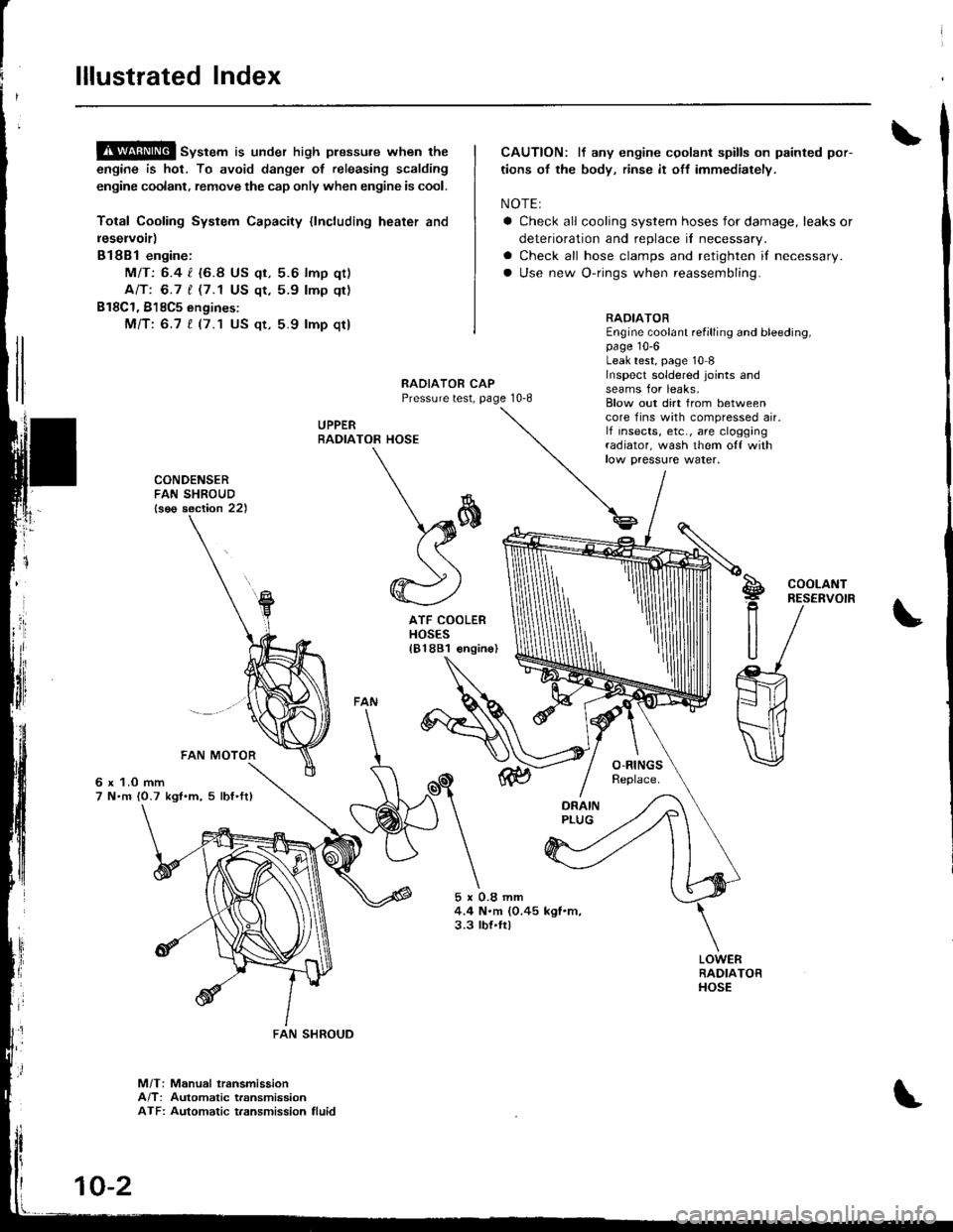
lllustrated Index
!$!!@ sv"t"m is under high plessure when the
engine is hot, To avoid dangei of releasing scalding
engine coolant, remove the cap only when engine is cool.
Total Cooling System Capacity {lncluding heater and
leservoir)
Bl8Bl engine:
MIT: 6.4 l. {6.8 US qt, 5.6 lmp qt)
Ant 6.7 t (7.1 US qt,5.9 lmp qt)
B18C1, 818C5 engines:
Mfi:6.7 t (7.1 US qt, 5.9 lmp qt)
CAUTION: lf any engine cgolant spills on painted por-
tions of the body, rinse it off immediately.
NOTE:
a Check all cooling system hoses for damage, leaks or
deterioration and replace il necessary.
a Check all hose clamps and retighten if necessary.
a Use new O-rings when reassembling.
RADIATOREngine coolant refilling and bleeding,page 10-6Leak test, page 10 8Inspecl soldered joints andseams for leaks,RAOIATOR CAPPressure test, page 10-8
UPPERRADIA
rl
]
CONDENSERFAN SHROUD{s€o section 22)
6 x 1.0 mm7 N.m {0.7 kgl.m, 5 lbf'ftl
5x0.8mm4.4 N.m (0.45 kgl.m,3.3 tbt.ft)
Blow out dirt from betweencore fins with compressed air.lf insects, etc., are cloggingradiator, wash them o{f withlow paessure water,
TOR HOSE
\*
\sffi((
@)
ATF COOLERHOSES181881 €ngin
S!g
R
U
COOLANTRESERVOIR
M/T: Manual lransmissionA/T: Automatic transmissionATF: Automatic t.ansmission fluid
FAN SHROUD
10-2
Page 198 of 1680
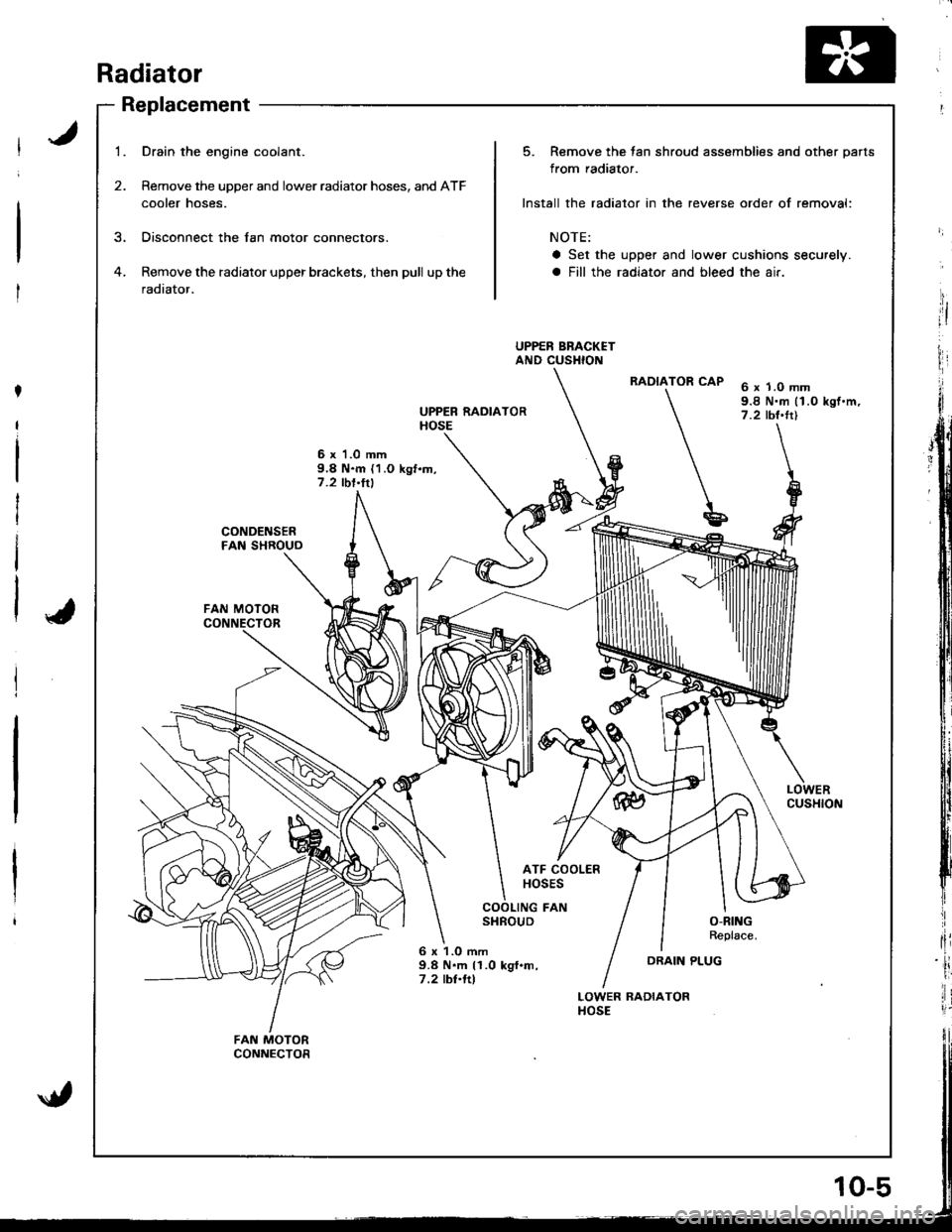
Radiator
Replacement
1.
2.
Drain the engine coolant.
Remove the upper and lower radiator hoses, and ATF
cooler hoses.
Disconnect the lan motor connectors.
Remove the radiator upper brackets, then pull up the
radiator.
6 x 'l .0 mm9,8 N.m {1.O kgf.m,7.2 tbl'ltl
UPPER RADIATORHOSE
6 x 1.0 mm9.8 N.m (1.0 kgf.m,7.2 tbt'trl
LOWERCUSHION
CONDENSERFAN SHROUO
FAN MOTOR
ATF COOLERHOSES
COOLING FANSHROUDO-RINGReplace.
6 x 1.O mm9.8 N.m 11.0 kgf.m,7 .2 tbl.ftl
LOWER RADIATORHOSE
FAN MOTORCONNECTOR
5. Remove the tan shroud assemblies and other parts
from radiator.
Install the radiator in the reverse order of removal:
NOTE:
a Set the upper and lower cushions securely.
a Fill the radiator and bleed the air.
UPPER BRACKETAND CUSHION
RADIATOR CAP
u
DRAIN PLUG
jit
I
HI
I
fli
ii
lir
Page 200 of 1680
8.Mix the recommended antifreeze with an equal
amount of water in a clean container.
NOTE:
a Use only genuine Honda antifreeze/coolant.
a For best corrosion protection, the coolant concen-
tration must be maintained year-round at 500,6
minimum. Coolant concentrations less than 507o
may not provide sufficient protection against cor,
rosion or freezing.
a Coolant concentrations greater than 60% will im-
pair cooling efliciency and are not recommended.
CAUTION:
a Do not mix different brands of anti-lrcezel
coolants.
a Do not use additional rust inhibitots or anti-tustproducts; they may not be compatible with the
coolant.
Engine Coolant Refill Capacity [including reservoir
{0.6 { (0.6 US qt, 0.5 lmp qr)ll:
81881 engine:
Ml7:1-1t {/t.6 US qt. 3.9 lmp qtl
818B1, 818C1 engin€s:
AlTt 1.7 | 15.0 US qt, 4.1 lmp qt)
818C1, B18C5 engines:
MlTt 1.7 t 15.0 US $, 4.1 lmp qtl
FILLER NECK
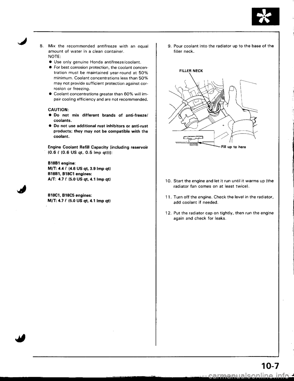
9.Pour coolant into the radiator up to the base of the
tiller neck.
10. Startthe engine and let jt run until itwarmsup(the
radiator fan comes on at least twice).
1 1 . Turn olf the engine. Check the level in the radiator,
add coolant if needed.
'12. Put the radiator cap on tightly, then run the engine
again and check for leaks.
10-7
Page 253 of 1680
3.Fuel Cut-off Control
. Du ring dece leration with the th rottle va lve closed, cu rrent to the fuel injectors is cutoffto improvefuel economyat
speeds over following rpm:. B'1881 engine: 970 rpm {Canada model: 1.050 rpm). B18C1 engine:970 rpm {Canada model: 1.050 rpm). 818C5 engine: 1,300 rpm (Canada model: 1,400 rpm)
. Fuel cut-off action also takes place when engine speed exceeds 7,000 rpm (B'1881 engine), 8.100 rpm (818C1
engine) or 8,600 rpm (818C5 engine), regardless ol the position of the thronle valve, to protect the engine from
over-revving.
A,,/C ComDressor Clutch Relav
When the ECM receives a demand for cooling from the air conditioning system, it delays the compressor from being
energized, and enriches the mixture to assure smooth transition to the A,/C mode.
Evaporative Emission (EVAP) Purge Control Solenoid Valve
When the engine coolanl temperature is above '154'F (68'C) and the air conditioner on. the ECM controls the EVAPpurge control solenoid valve which controls vacuum to the EVAP purge control canister.
Intake Air Eypass (lAB) Control Solenoid Valve*a
When the engine rpm is below 5,750 rpm, rhe IAB control solenoid valve is activated by a signal from the ECM, intake
air flows through the long intake path, then high torque is delivered. At speeds higher than 5,750 rpm, the solenoidvalve is deactivated by the ECM, and intake air flows through the short intake path in order to reduce the resistance in
airflow.
Sell-diagnosis Function lMalfunction Indicator Lamp {MlL)lWhen an abnormality occurs in a signal from a sensor, the ECM supplies ground for the MIL and stores the code in
erasable memory. When the ignition is initially turned on, the ECM supplies ground for the N4lL tor two seconds to
check the MIL bulb condition.
Two Driving Cycle Detection Method
To prevent false indications, the Two Driving Cycle Detection Method is used for the HO2S, fuel metering-related, idle
control system, ECT sensor, TWC and EVAP control system and other self-diagnostic functions, When an abnormality
occurs, the ECM stores it in its memory. When the same abnormality recurs after the ignition switch is turned OFFand ON (ll)again, the ECM informs the driver by lighting the MlL.
However, to ease troubleshooting, this function is cancelled when you shon the service check connector. The MIL will
then blink immediately when an abnormality occurs.
4.
5.
6.
3.
4.
ECM Fail-safe/8ack.up F0nctions
1. Fail-sate Function
When an abnormality occurs in a signal from a sensor, the ECM ignores that signal and assumes a pre-programmed
value for that sensor that allows the enqine to continue to run.
2. Back-uo Function
When an abnormality occurs in the ECM itself, the fuel injectors are controlled by a back-up circuit independent of the
system in order to permit minimal driving.
11-49
Page 342 of 1680
t"iI
Emission Gontrol System
System Description
Three Way Catalytic Converter (TWCI
\
t
The emission control system includes a Three Way
Catalytic Converter (TWC), Positive Crankcase Ventilation
(PCV) system and Evaporative Emission (EVAP) Control
system. The emission control system is designed to meet
tederal and state emission standards.
InsDeciion
!@@ Do not smoke during this procedure. Keep
any open llame away from your work area.
1. Start the engine. Hold the engine at 3,000 rpm with
no load {in Park or neutral) until the radiator fan
comes on, then let it idle.
2. Connect a tachometer.
Check and adjust the idle speed, if necessary (see
page '11-11 ! ).
Warm up and calibrate the CO meter according to the
meter manufacturer's instructions.
Check idle CO with rhe headlights, heater blower,
rear window defogger, cooling fan, and air condition-
er off.
NOTE: {Canada) Pull the parking brake lever up.
Start the engine, then check that the headlights are
olf.
CO meter should indicste 0.17o maximum.
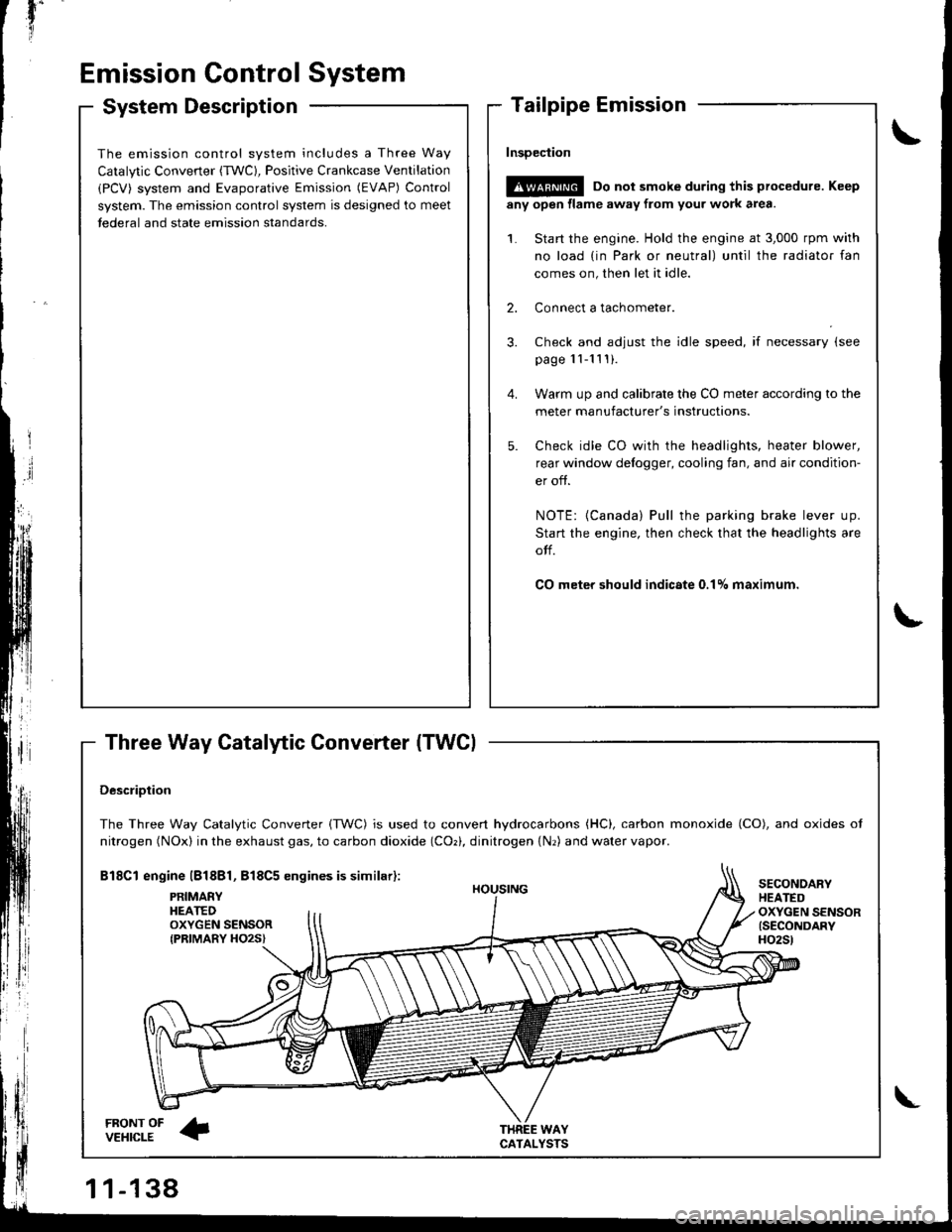
DescriDtion
The Three Way Catalytic Converter {TWC) is used to convert hydrocarbons (HC), carbon monoxide (CO), and oxides of
nitrogen (NOx) in the exhaust gas, to carbon dioxide (COr), dinitrogen {Nr) and water vapor.
Bl8Cl engine l818Bl, 818C5 engines is similar):
FRONT OFVEHICLE
PRIMAEYHEATEDOXYGEN SENSORIPRIMARY HO2S}
HOUSING
WAYCATALYSTS
SECONOARYHEATEDOXYGEN SENSOR{SECONDARYH02St
\
Page 513 of 1680
Stall Speed
V
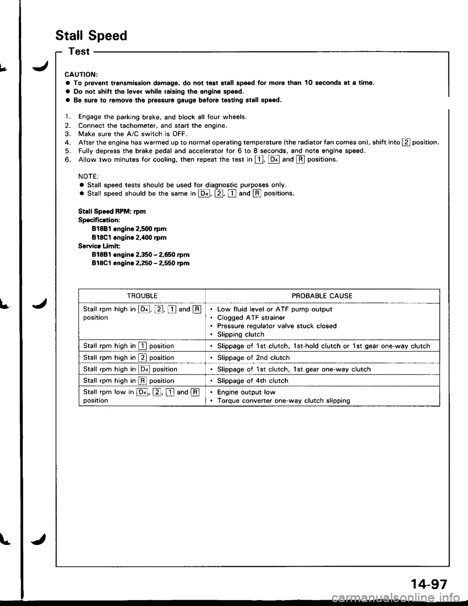
€nt transmission damage, do not tost stall speod for mol€ than
shitt tho lever while raising the engina speed,
10 soconds at a time.
L
CAUTION:
a To prev€nt transmission damage, do not tost stall speod for mol€ than 10 soconds at a time.
a Do not shitt tho lever while raising the engina speed,
a Be suro to remove tho plossule gaugo bolore testing st8ll spe€d.
1. Engage the parking brake. and block all lour wheels.
2. Connect the tachometer, and start the engine,
3. Make sure the A/C switch is OFF.
4. After the engine has warmed up to normal operating temperature {the radiator fan comes on), shift into g position.
5. Fully depress the brake pedal and accelerator for 6 to I seconds. and note engine speed.
6. Allow two minutes for cooling, then repeat the test in [, [Dll and @ oositions.
NOTE:
a Stall speed tests should be used tor diagnostic purposes only.
. Stall speed should be the same in E, tr, tr and @ Fositions.
Stall Speed FPM: rpm
Specification:
Bl88l €ngine 2,5q) rpm
Bl8Cl engine 2.i|{10 .pm
Sorvice Limit:
81881 engins 2,350 - 2,650 rpm
Bl8Ct ongine 2,250 - 2,550 rpm
TROUBLEPROBABLE CAUSE
Stall rpm hish in E, E, I and @position
Low tluid level or ATF pump output
Clogged ATF strainer
Pressure regulator valve stuck closed
Slipping clutch
Stall rpm high in I positionSlippage of 1st clutch, 1st-hold clutch or 1st gear one-way clutch
Stall rpm high in E positionSlippage of 2nd clutch
Stall rpm high in ldnl posirionSlippage of 1st clutch. 1st gear one-way clutch
Stall rpm high in [!l positionSlippage of 4th clutch
Stall rpm low in E, E. I and @position
Engine output low
Torque convener one-way clutch slipping
14-97
Page 594 of 1680
Throttle Control Cable
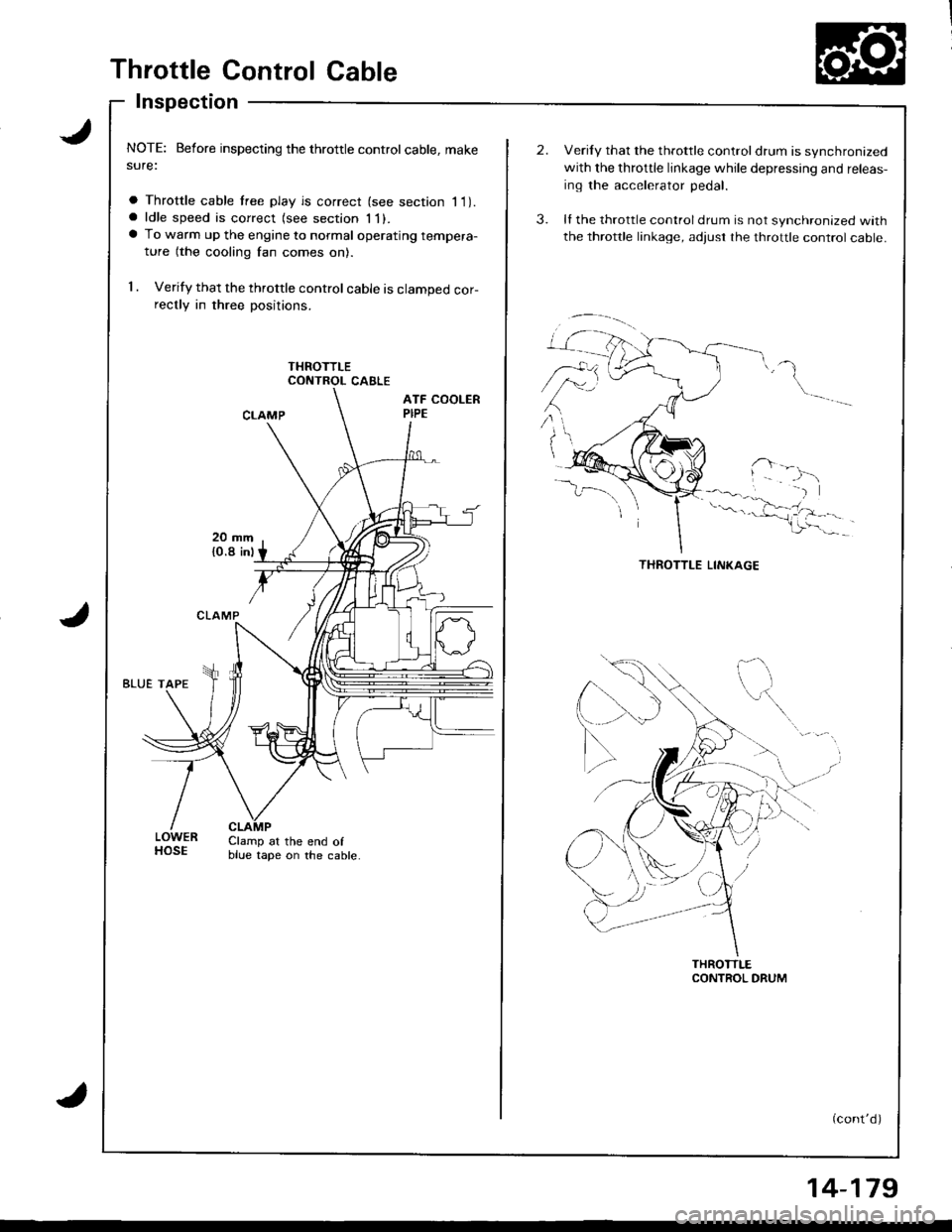
Inspection
NOTE: Before inspecting the throttle controlcable, makesure:
a Throttle cable tree play is correct (see section I 1).a ldle speed is correct (see section 1l).a To warm up the engine to normal operating tempera-
ture (the cooling fan comes on).
1 . Verify that the throttle control cable is clamped cor-rectly in three positions.
CONTROL CABLE
LOWERHOSEClamp at the end ofblue tape on the cable.
Verily that the throttle controldrum is synchronized
with the throttle linkage while depressing and releas-
ing the accelerator pedal.
ll the throttle control drum is not synchronized with
the throttle linkage, adjust rhe throttle control cable.
(cont'd)
14-179
Page 596 of 1680
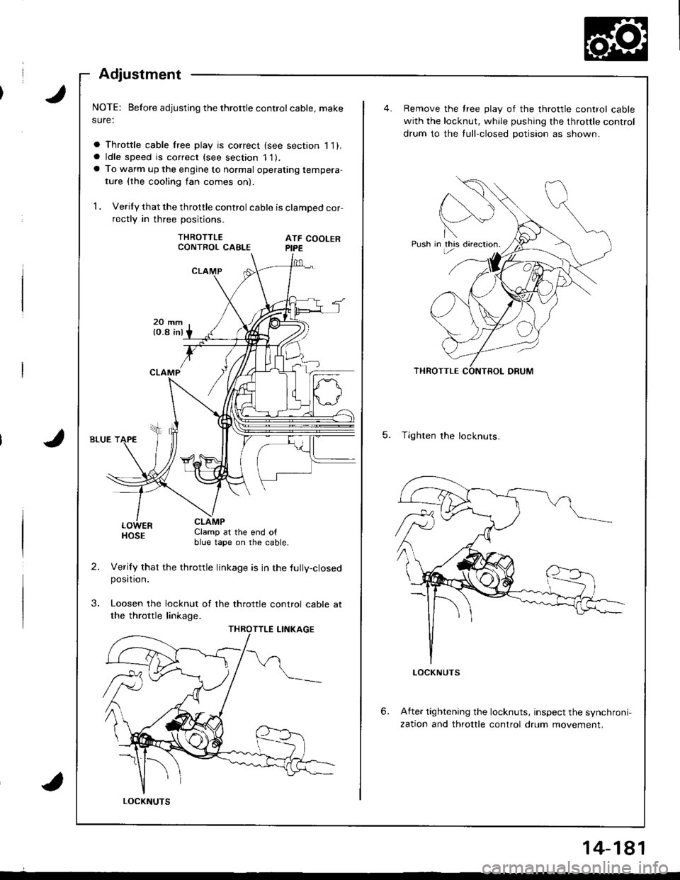
Adjustment
NOTE: Before adjusting the throttle controlcable, make
sure:
a Throttle cable lree play is correct (see section 11).a ldle speed is correct (see section 11).a To warm up the engine to normal operating tempera-
ture {the cooling fan comes on)
1 . Verify that the throttle control cable is clamped correctly in three positions.
THROTTLEATF COOLERPIPE
LOWERHOSEClamp at the end ofblue tape on the cable.
Verily that the throttle linkage is in the fully-closedposttron.
Loosen the locknut of the throttle control cable at
the throttle linkage.
CONTROL CABLE
LOCKNUTS
14-181
Push in this directron.
Remove the free play of the throttle control cable
with the locknut, while pushing the throttle control
drum to the tull-closed potision as shown.
5. Tighten the locknuts.
6.After tightening the locknuts, inspect the synchroni-
zation and throttle control drum movement.
Page 1024 of 1680

J
Troubleshooting
Reference Chart
. Any abnormality must be corrected before continuing the test.. Because of the precise measurements needed, use a multimeter when testing.
Before performing any troubleshooting procedures check:. Fuses No, 56 (20 A), No. 57 (20 A) in the under-hood fuse/relay box, and No. 17 {7.5 A) in rhe under-dash fuse/relay box.. Grounds No. G401, G201, G151, G101. Cleanliness and tightness of all connectors
I'IT
I
I
SYMPTOMREMEDY
Radiator fan does not run at all.Perform the procedures in the flowchart {see page 22-8).
Condenser fan does not run at all,Perform the procedures in the flowchart (see page 22-1O1.
Both fans {radiator and condenser) do not
run for engine cooling, but they both run
with the IVC on.
Perform the procedures in the tlowchart (see page 22-12).
Both fans do not run at all.Perform the procedures in the flowchart (see page 22-13).
Compressor clutch does not engage.Perform the procedures in the flowchart (see page 22-14).
l'lc system does not come on
{compressor and both fans).Perform the procedures in the flowchart (see page 22-15).
22-7
Page 1029 of 1680
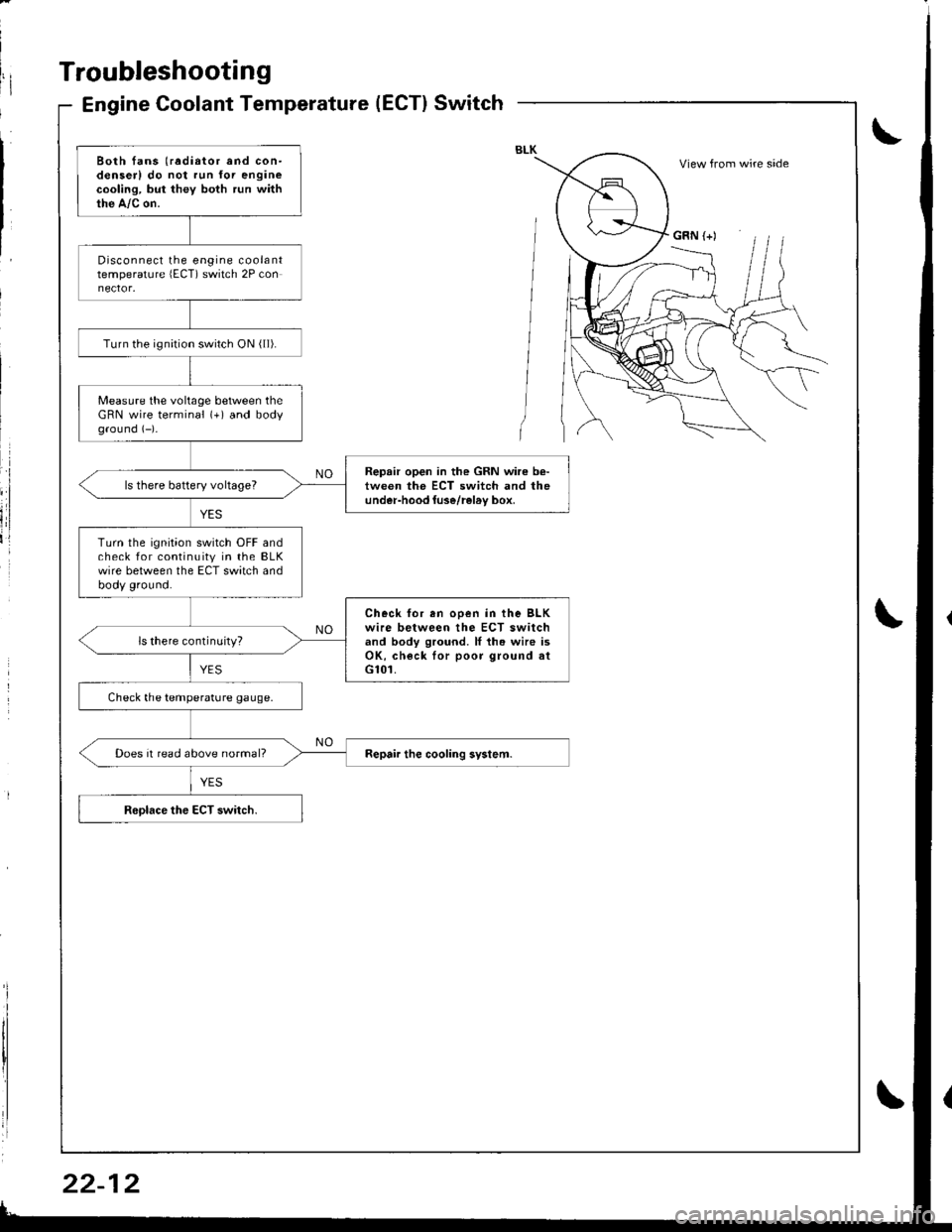
Troubleshooting
Engine Coolant Temperature(ECT}Switch
Both fans (radiator and con-denserl do not run for enginecooling, but they both run withthe A,/c on.
Disconnect the engine coolanttemperature lECT) switch 2P con
Turn the ignirion switch ON ( ll).
Measure the voltage between theGRN wire terminal (+) and bodyground (-)-
Repair open in the GRN wire b€-tween the ECT switch and theunder-hood luse/rel6v box,ls there battery voltageT
Turn the ignition switch OFF andcheck for continuity in the BLKwire between the ECT switch andbody ground.
Check for en ooen in the BLKwire between the ECT switchand body ground. ll th. wire isOK, check lor poor ground atG101.
ls there continuity?
Check the temperature gauge.
Does it read above normal?
View from wire side
GRN (+)