ESP ACURA INTEGRA 1998 Service Repair Manual
[x] Cancel search | Manufacturer: ACURA, Model Year: 1998, Model line: INTEGRA, Model: ACURA INTEGRA 1998Pages: 1680, PDF Size: 53.14 MB
Page 86 of 1680
\-
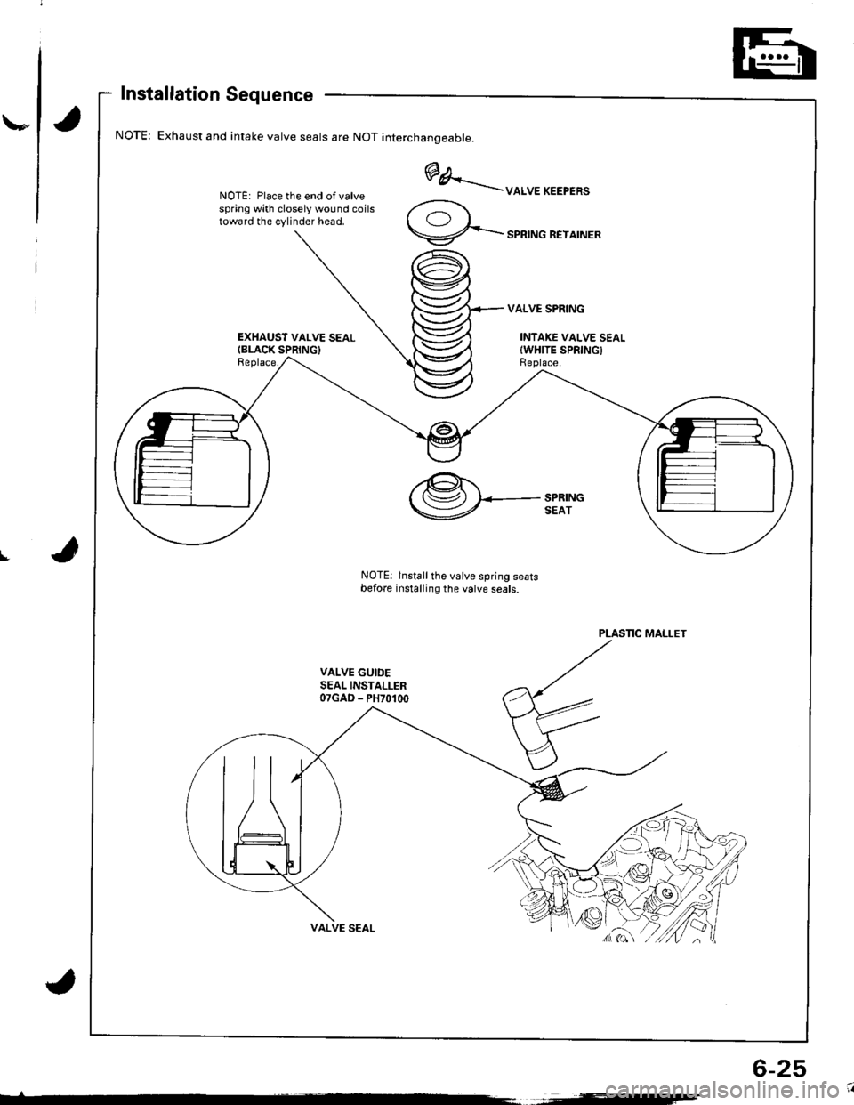
Installation Sequence
Exhaust and intake valve seals are NOT interchanoeable.
NOTE: Place the end of valvespring with closely wound coilstoward the cylinder head.
EXHAUST VALVE SEALIBLACK SPRING}Replace.
@A..'..--uoruEKEEPER'
9-...-'PRTNGREYATNER
VALVE SPRING
INTAKE VALVE SEALIWHITE SPRINGIReplace.
I
PLASTIC MALLET
VALVE GUIDESEAL INSTALLER07GAD - PH70100
,@.t.'( (Sz) I<-- SPRING
V SEAT
NOTE: lnstall the valve spring seatsbefore installing the valve seals.
6-25
Page 88 of 1680
\,
Replacement
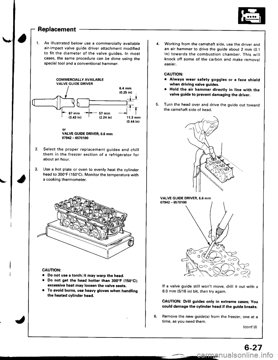
1. As illustrated below use a commercially available
air-impact valve guide driver attachment modified
to fit the diameter of the valve guides, In most
cases, the same procedure can be done using thespecial tool and a conventional hammer.
6.il mm{0.25 inl
rr
*f-::rtl1-r87 mm{3.43 in)11.3 mm10.44 inl
orVALVE GUIDE DBIVER, 6.6 mm07942 - 6570100
Select the proper replacement guides and chillthem in the freezer section of a refrigerator forabout an hour.
Use a hot plate or oven to evenly heat the cylinderhead to 300"F (150"C). Monitor the temperature witha cooking thermometer.
CAUTION:
. Do not use a torch; it may warp the hoad.. Do not ger tho head hotter than 300.F ltS0"C);exces3ive heat may loo3en the valvo seats.. To avoid burns, uss heaw gloves when handlingthe heat€d cylinder head.
12.21inl
6-27
Working trom the camshaft side, use the driver and8n air hammer to drive the guide about 2 mm (0.1
in) towards the combustion chamber. This willknock off some of the carbon and make removaleaster.
CAUTION:
. Always wear safety goggles or a face shieldwhen driving valve guides.
. Hold the air hammer direcfly in line with thevalve guide to prevent damaging the driver.
Turn the head over and drive the guide out towardthe camshaft side of head.
5.
VALVE GUIDE DRIVER.079i12 - 65701006.6 mm
lf a valve guide still won't move. drill it out with a
8.0 mm (5/16 in) bit, then try again.
CAUTION: Drill guides only in extreme cases; You
could damage the cylinder head it the guide breaks.
6. Remove the new guide{s) from the freezer, one at atime, as you need them.
{cont'd)
OO
'o c,
Page 154 of 1680
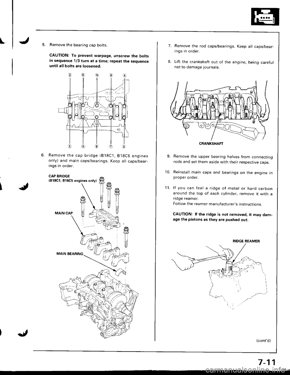
IRemove the bearing cap bolts.
CAUTION: To prevent warpage, unscrew the boltsin sequence 1/3 turn at a time; repeat the sequenceuntil all bolts are loosened.
\J
?, .ia --10) 3r O
Remove the cap bridge (818C1, B18Cb enginesonly) and main caps/bearings. Keep all caps/bear-ings in order.
CAP BRIDGE{818C1, 818C5 engines only}
MAIN CAP
MAIN BEARING
11
T
T
TI
7.Remove the rod caps/bearings. Keep all caps/bearings in order.
Lift the crankshaft out o{ the engine, being care{ulnot to damage journals.
CRANKSHAFT
9. Remove the upper bearing halves from connectingrods and set them aside with their respective caps.
10. Reinstall main caps and bearings on the engine inproper order.
11. lf you can feel a ridge oI metal or hard carbonaround the top of each cylinder, remove it with afldge reamer.
Follow the reamer manufacturer's instructions.
CAUTIONT lf the ridge is not lemoved, it may dam-age the pistons as they are pushed out.
(cont'd)
7-11
RIDGE REAMER
Page 176 of 1680
lllustrated Index
(cont'dl
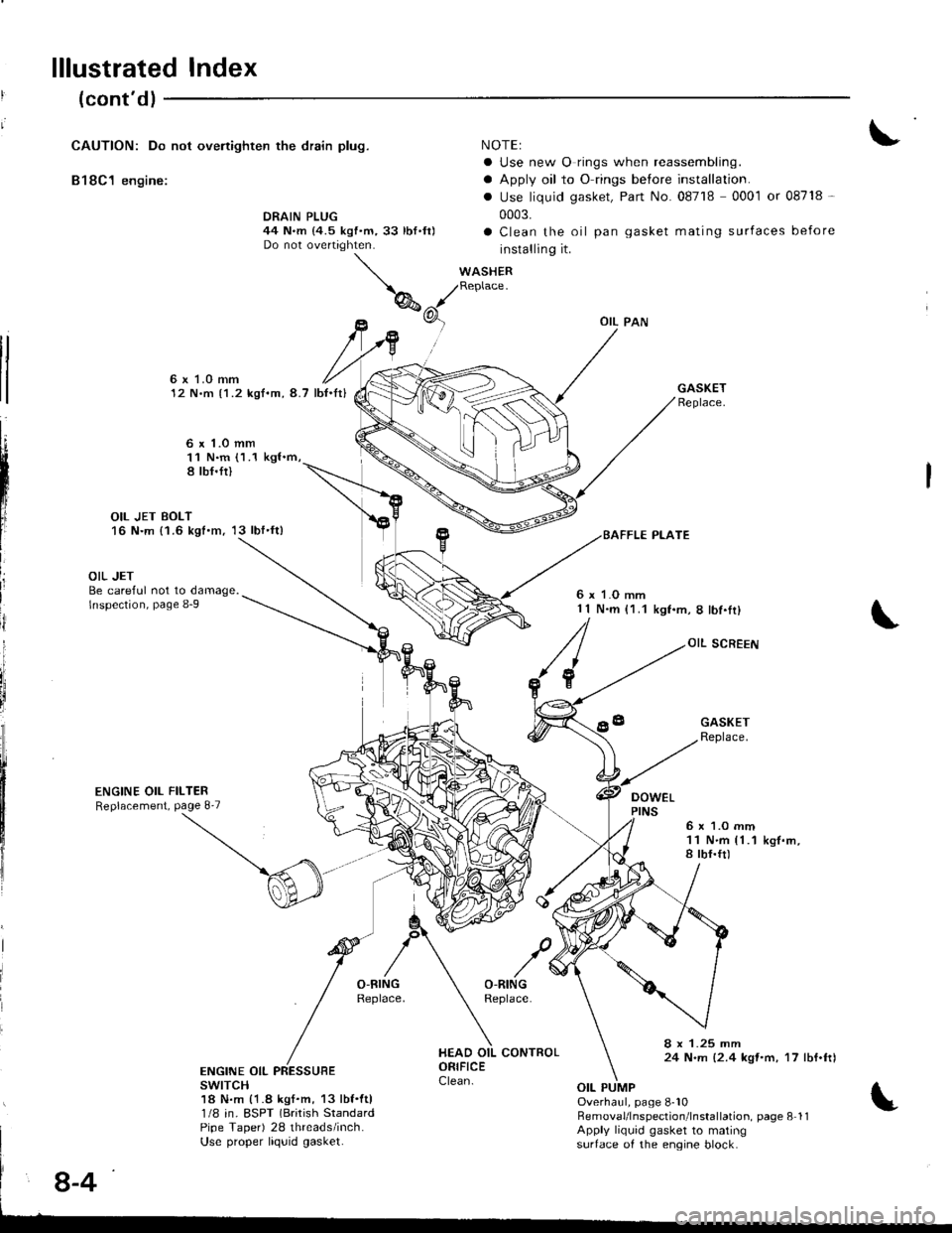
CAUTION: Do not ovenighten the drain plug.
B18C1 engine:
NOTEI
a Use new O rings when reassembling.
a Apply oil to O rings before installation.
. Use liquid gasket, Part No. 08718 0001 or 08718 -
0003.
a Clean the oil pan gasket mating surfaces before
installing it.
WASHERReplace.
DRAIN PLUG44 N.m {4.5 kgf.m,33 lbf.ft)Do not overtighten.
tl
tl
6x LO mm12 N.m {1.2 kgf.m, 8.7 lb{.It}
6 x 1.o mm11 N.m (1.1 kgl.m,8 tbf.fi)
OIL JET BOLT16 N.m {1.6 kgt.m, 13 lbf'ft)
L
III
ij
i
OIL JETBe careful not to damage.lnspection, page 8-9
ENGINE OIL FILTERReplacement, Page 8'7
6 x 1.O mm1 1 N.m (1.1kgf.m,8lbf.Ir)
OIL SCREEN
DOWEL
GASKETReplace.
6x 1.O mm11 N.m {1.1a tbf.ft)k9f.m,
8 x 1.25 mm24 N.m {2.4 kqt'm, 17 lbf.ftlENGINE OIL PRESSUBEswrTcH18 N.m {1.8 kgf.m, 13 lbf.ftl1/8 in. ESPT (Brirish StandardPipe Taper) 28 threads/inch.Use proper liquid gasket.
Overhaul, page 8-10RemovaUlnspection'lnstallation. page 8 11Apply liquid gasket to matingsurtace of the engine block.
8-4
Page 241 of 1680
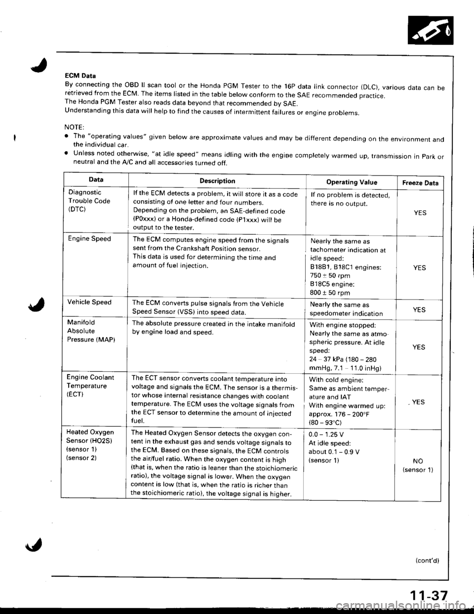
ECM Data
By connecting the OBD ll scan tool or the Honda PGM Tester to the 16P data link connector (DLC), various data can beretrieved from the EcM The items risted in the tabre berow conform to the sAE recommended practice.The Honda PGM Tester also reads data beyond that recommended bv SAE.understanding this data wirl herp to rind the causes of intermiftent fairures or engine probrems.
NOTE:
' The "operatlng values" given below are approximate values and may be different depending on the environment andthe individual car.' Unless noted otherwise, "at idle speed" means idling with the engiFe completely warmed up, transmissron in park orneutral and the A,/C and all accessories turned off.
DataDescriptionOperating ValueFreeze Data
Diagnostic
Trouble Code(DTC)
lf the ECM detects a problem, it will store tt as a cocteconsisting ot one letter and four numbers.Depending on the problem, an SAE-defined code{Poxxx) or a Honda-defined code (plxxx) will beoutput to the lester.
lf no problem is detected,
there is no output.
YES
Engine SpeedThe ECM computes engine speed from the signalssent from the Crankshaft Position sensor.This data is used for determining the I|me andamount of fuel injection.
Nearly the same as
tachometer indication at
idle speed:
81881,818C1 engines:
750 t 50 rpm
818C5 engine:
800 1 50 rpm
YES
Vehicle SpeedThe ECM converts pulse signals trom the VehicleSpeed Sensor (VSS) into speed data.
Nearly the same as
speedometer indicationYES
Manitold
Absolute
Pressure {MAP)
The absolute pressure created in the intake manifoldby engine load and speed.With engine stopped:
Nearly the same as atmo
spheric pressure. At idle
speed:
24 - 37 kPa (180 - 280
mmHg,7.1 1'1.0 inHg)
YES
Engine Coolant
Temperature
(ECT)
The ECT sensor converts coolant temperature intovoltage and signals the ECM. The sensor is a thermis-tor whose internal resistance changes with coolanttemperature. The ECM uses the voltage signals fromlhe ECT sensor to determine the amount of iniectedfuel.
With cold engine:
Same as ambient temper
ature and IAT
With engine warmed up:
approx. 176 - 200'F
{80 - 93.C)
, YES
Heated Oxygen
Sensor (HO2S)
{sensor 1)(sensor 2)
The Heated Oxygen Sensor detects the oxygen con-tent in the exhaust gas and sends voltage signals tothe ECM. Based on these signals,lhe ECM controlsthe airlfuel ratio. When the oxygen content is high{that is, when the ratio is leaner than the stoichiomericratio), the voltage signal is lower. When the oxygencontent is low (that is, when the ratio is richer thanthe stoichiomeric ratio), the voltage signal is higher.
0.0 - 1.25 V
At idle speed:
abour 0.'1 - 0.9 V(sensor I )NO(sensor 1)
(conl'd)
11-37
Page 245 of 1680
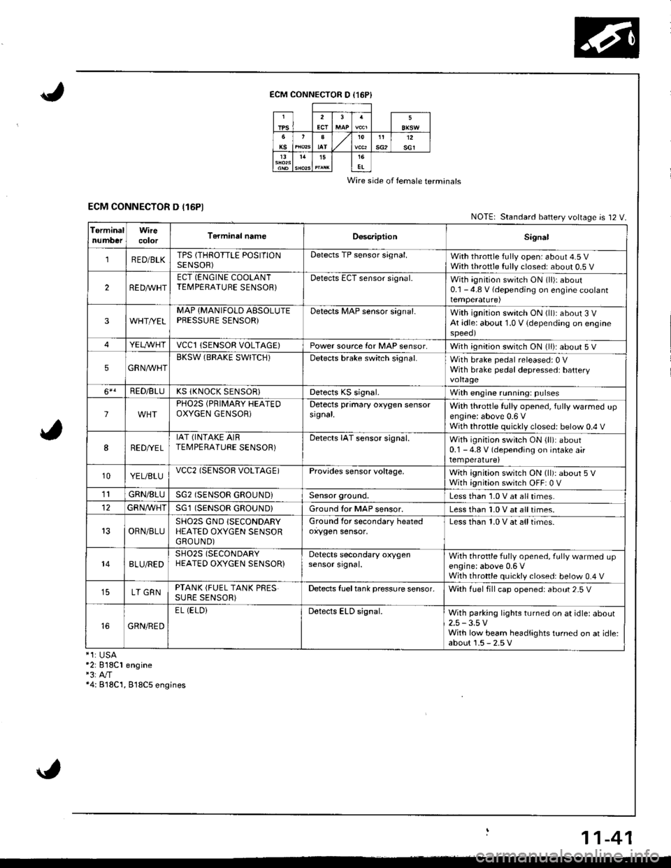
ECM CONNECTOR D (16P}
Wire side of female terminals
ECM CONNECTOR D (16P1NOTE| Standard battery voltage is 12 V.
TerminalnumberWirecolorT6rminal nameDoscriptionSignal
1RED/BLKTPS (THROTTLE POSITIONSENSOR)Detects TP sensor s;gnal.With throttle fully open: about 4.5 VWith throttle fully closed: about 0.5 V
2REDAr'r'HTECT (ENGINE COOLANTTEMPERATUBE SENSOB}Detects ECT sensor signal.With ignition switch ON (ll)r about0.1 - 4.8 V (depending on engine coolanttemperalure)
3WHT//ELMAP {MANIFOLD AESOLUTEPBESSURE SENSOR)Detects MAP sensor signal.With ignition switch ON (ll)iabout 3 VAt idle: about 1.0 V {depending on enginespeeol
4YELA/VHTvccl{SENSOR VOLTAGE)Power source for MAP sensor,With ignition switch ON (ll): about 5 V
5GRNAVHTBKSW (BRAKE SWITCH)Detects brake switch signal.With brake pedal released: 0 VWith brake pedal depressed: batteryvoltage
6*!RED/BLUKS (KNOCK SENSOR}Detects KS signal.With engine running: pulses
lPHO2S (PRIMARY HEATEDOXYGEN GENSOR)Detects primary oxygen sensorsignal.With throttle fully opened, fully warmed upengine: above 0.6 VWith throttle quickly closed: below 0.4 V
8RED/VEL
IAT (INTAKE AIRTEMPERATURE SENSOR)Detects IAT sensor signal.With ignition switch ON {ll): about0.1 - 4.8 V (depending on intake airtemperature)
10YEL/BLUvcc2(SENSOB VOLTAGE)Provides sensor voltage,With ignition switch ON (ll): about 5 VWith ignition switch OFF: 0 V
1lGRN/8LUSG2 (SENSOR GROUND}Sensor ground.Less than 1.0 V at all times.
GFNA/VHT(SENSOR GROUND}Ground tor MAP sensor.Less than 1.0 V at all times.
OBN/BLUSHO2S GND (SECONDARY
HEATED OXYGEN SENSORGROUND)
Ground for secondary heatedoxygen sensor,Less than 1.0 V at alltimes.
148LU/REDSH02S (SECONDARY
HEATED OXYGEN SENSOR}Detects secondary oxygensensor srgnal.With throttle fully opened. fully warmed upengine: above 0,6 VWith throttle quickly closed: below 0.4 V
LT GRNPTANK (FUEL TANK PRESSURE SENSOR)Detects fueltank pressure sensor.With luel fill cap opened: about 2-5 V
GRN/RED
EL (ELOiDetects ELD signal.With parking lights turned on at idle: about2.5 -3.5 VWith low beam headlights turned on at idle:about 1.5 - 2.5 V*1:USA*2: 818C1 engine"3:A"/T*4: B18C'1, 818C5 engines
11-41
Page 246 of 1680

1l
Troubleshooting
Diagnostic Trouble Gode (DTCI Chart
*: These DTCS will be indicated by the blinking ot the lvalfunction Indicator Lamp (MlL) with the SCS service connector
connected.
Ia
\
\
il
\
DTC
lMlL indication*lDetection ltemProbabls CausePage
P0107 (3)
Manifold Absolute
Pressure Circuit
Low Input
Open or short in MAP sensor circuit
MAP sensor
ECM
'11-54
P0108 (31
Manifold Absolute
Pressure Circuit
High Input
Open in MAP sensor circuit
MAP sensor
ECM
tt-5t,
P0112 (10)
Intake Air
Temperature Circuit
Low Input
Short in IAT sensor circuit
IAT sensor
ECM
11.58
P0113 {10)
lntake Air
Temperature Circuit
High Input
Open in IAT sensor circuit
IAT sensor
ECM
1'�1-59
P0116 (86)
Engine Coolant
Temperature Circuit
Range/Performance Problem
. ECT sensor' Cooling system11-60
P0117 (6)
Engine Coolant
Temperature Circuit
Low Input
Short in ECT sensor circuit
ECT sensor
ECM
1 '�t-61
P0118 {6)
Engine Coolant
Temperature Circuit
High Input
Open in ECT sensor circuit
ECT sensor
ECt\,4
1't -62
P0122l7l
Throttle Position
Circuit
Low Input
Open or shon in TP sensor circuit
TP sensor
ECM
11,63
P0123 (7)
Throttle Position
Circuit
High Input
Open in TP sensor circuit
TP sensor
ECM
I t-oc
P0131 (1 )
Primary Heated Oxygen Sensor
Circuit Low Voltage (Sensor 1)
Shon in Primary HO2S (Sensor'l) circuit
Primary H02S {Sensor 1)
Fuel supply system
ECM
11-67
P0132 (1)Primary Heated Oxygen Sensor
Circuit High Voitage (Sensor 1)
Open in Primary HO2S (Sensor 1) circuit
Primary HO2S (Sensor 1)
ECM
11-69
P0133 (61)Primary Heated Oxygen Sensor
Slow Response (Sensor 1)
. Primary HO2S (Sensor 1). Exhaust system1 1-70
,r:' 11-42
L
Page 247 of 1680
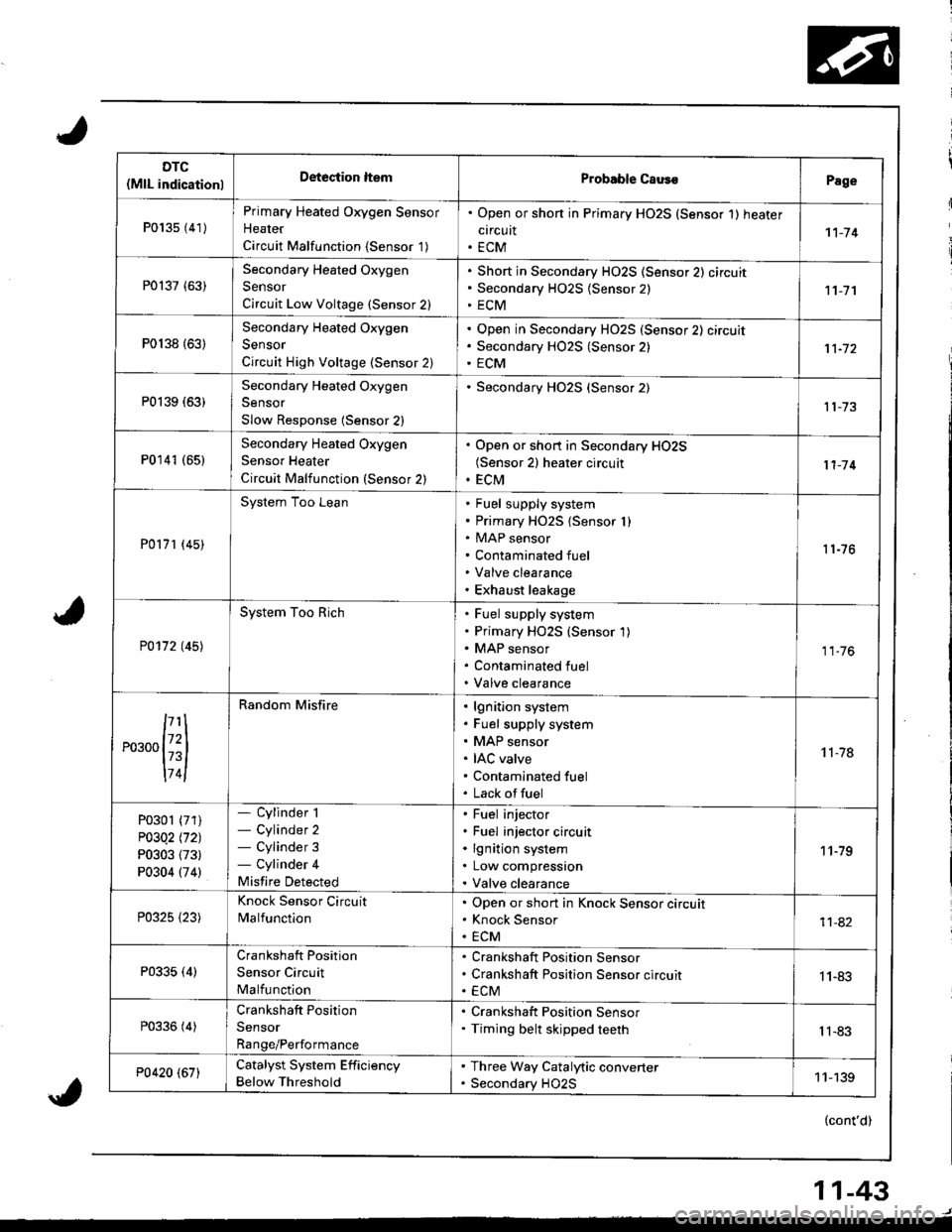
DTC(MlL indicationlDeteciion ltemProbable CausoPage
P013s {41)
Primary Heated Oxygen Sensor
Heater
Circuit Malfunction {Sensor '1)
. Open or shon in Primary HO2S (Sensor 1) heater
circuit. ECM1't-74
P0137 (63)Secondary Heated Oxygen
Sensor
Circuit Low Voltage (Sensor 2)
Short in Secondary HO2S (Sensor 2) circuit
Secondary H02S {Sensor 2)
ECM11-7'l
P0138 {63)
Secondary Heated Oxygen
Sensor
Circuit High Voltage (Sensor 2)
Open in Secondary HO2S (Sensor 2) circuit
Secondary HO2S (Sensor 2)
ECM
P0139 (63)Secondary Heated Oxygen
Sensor
Slow Response (Sensor 2)
Secondary HO2S (Sensor 2)
P0141 (651Secondary Heated Oxygen
Sensor Heater
Circuit Malfunction (Sensor 2)
. Open or short in Secondary HO2S(Sensor 2) heater circuit. ECM11-'14
P0171 (45)
System Too LeanFuel supply system
Primary HO2S {Sensor I )MAP sensor
Contaminated fuel
Valve clearance
Exhaust leakage
11-76
P0172 t45l
System Too RichFuel supply system
Primary HO2S (Sensor 1)
MAP sensor
Contaminated fuel
Valve clearance
11.76
,...,{iil
174l
Random Misfirelgnition system
Fuel supply system
MAP sensor
IAC valve
Contaminated fuel
Lack offuel
't 1-78
P0301 (71)
P03Q2 l'121
P0303 (73)
P0304 (74)
- Cylinder 1- Cylinder 2- Cylinder 3- Cylinder 4
Misfire Detected
Fuel injector
Fuel injector circuit
lgnition system
Low compression
Valve clearance
11-79
P0325 {23)
Knock Sensor Circuit
MalfunctionOpen or short in Knock Sensor circuit
Knock Sensor
ECM11-82
P0335 (4)Crankshaft Position
Sensor Circuit
Malfunction
Crankshaft Position Sensor
Crankshaft Position Sensor circuit
ECM1 1-83
P0336 (4)Crankshaft Position
Sensor
Range/Performance
. Crankshaft Position Sensor. Timing belt skipped teethIl-83
P0420 (67)Catalyst System Efficiency
Below Threshold
. Three Way Catalytic converter. Secondary HO2S11-139
(cont'd)
11-43
Page 274 of 1680
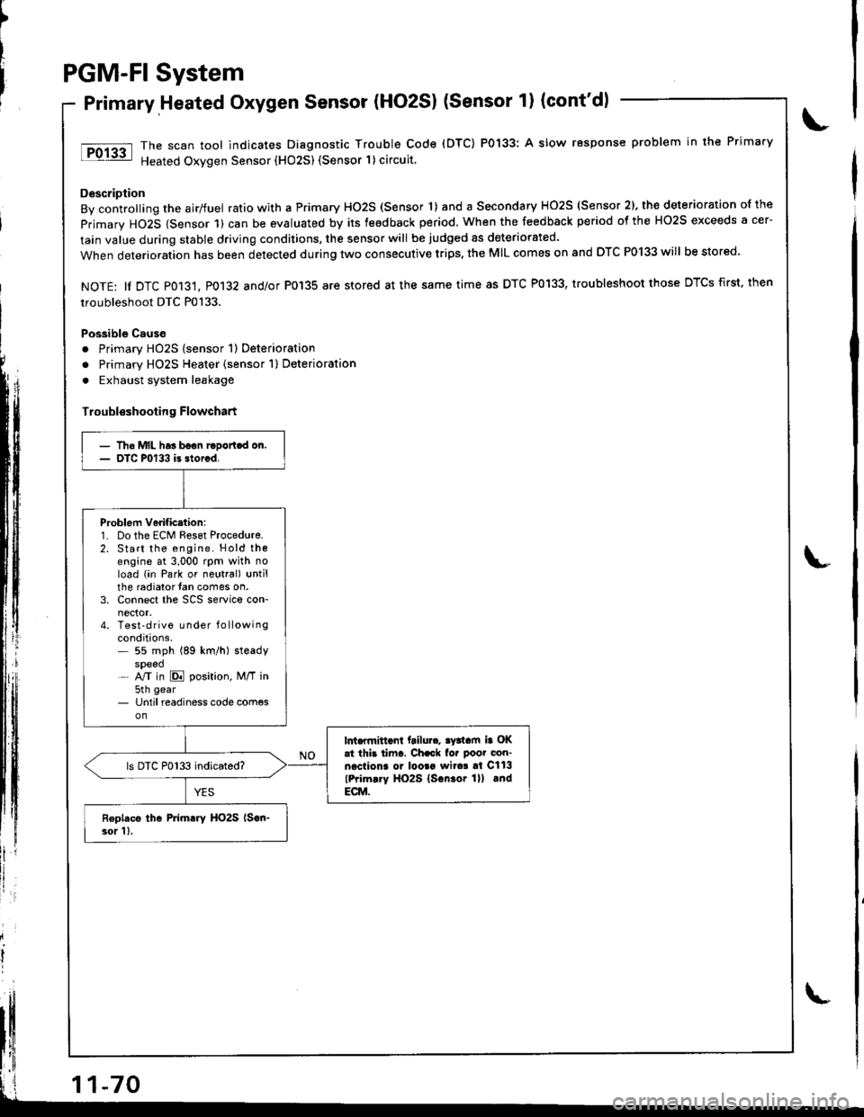
PGM-FI System
Primary,Heated Oxygen Sensor (HO2S) (Sensor 1) (cont'dl
The scan tool indicates Diagnostic Trouble Code (DTC) P0133: A slow response problem in the Primary
Heated Oxygen Sensor (HO25) (Sensor 1) circuit.
Description
By controlling the airlfuel ratio with a Primary HO2S (Sensor 'l) and a Secondary HO2S (Sensor 2), the deterioration of the
primary HO2S {Sensor 1) can be evaluated by its teedback period. When the feedback period of the HO2S exceeds a cer-
lain value during stable driving conditions, the sensor will be judged as deteriorated.
When deterioration has been detected during two consecutive trips, the MIL comes on and DTC P0133 will be stored
NOTE: ll DTC P013't, P0132 and/or P0'135 are stored at the same time as DTC P0133, troubleshoot those DTCS first, then
troubleshoot DTC P0133.
Possible Cause
. Primary HO2S (sensor 1) Deterioration
o Primary HO2S Heater (sensor 1) Deterioration
. Exhaust system leakage
Troubl€shooting Flowchart
')
litll r
- Tho MIL has boon raDortcd on.- DTC P0133 is storcd.
Problem verificttion:1. Do the ECM Reset Procedure.2. Start the engine. Hold thoengine at 3,000 rpm with noload (in Park or neutral) untilthe radiator fan comes on.3. Connect the SCS service con-
4. Test'drive Lrnder f o llowingconditions.* 55 mph (89 km/h) steadyspeed- NT in E position, M/T in5th gear- Until readiness code com€son
lnt.flnittcnt ftilu... ay3tam ia OKat thb tiinr. Ch.ck fo. poor con-necliona o. looaa wita! al Cll3
lPrim.ry HO2S lscn.or lll lndECM.
ls DTC P0133 indicated?
Roplacs the Primary HO2S lscn-3or 1),
Page 277 of 1680
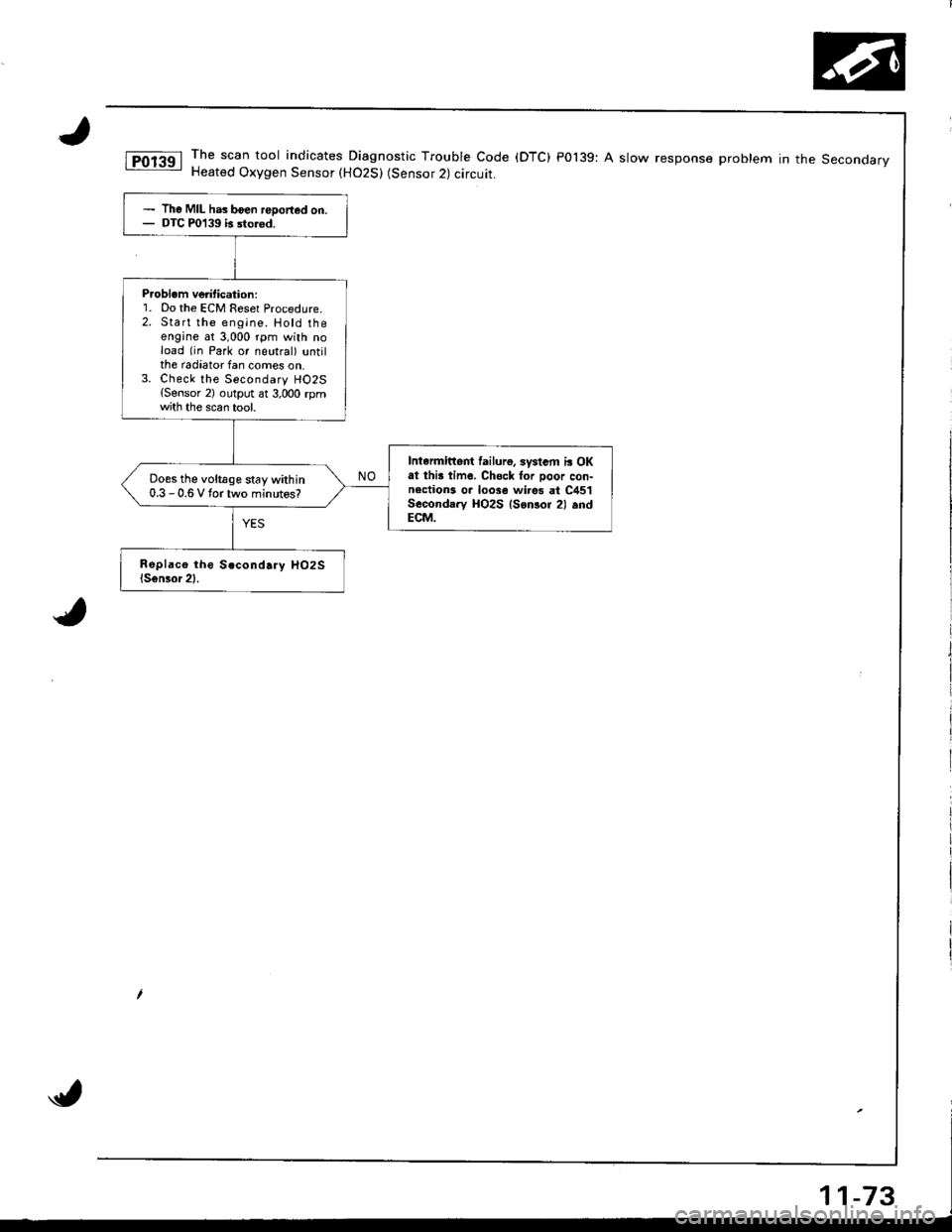
The scan tool indicates Diagnostic Trouble Code (DTC) P0139: A slow response problem in the SeconoarvHeated Oxygen Sensor (H02S) (Sensor 2) circuit.
The MIL has boen reDorted on.DTC P0139 b sto.od.
P.oblem ve tication:1. Do the ECM Reset Procedure.2. Start the engine. Hotd theengine at 3,000 rpm with noload (in Park or neutral) untilthe radiator fan comes on,3. Check the Secondary HO2S{Sensor 2) output ar 3,000 rpmth the scan tool.
Intarmittert lailurg, systsm i! OKat thi! time. Chsck for Door con-nections o. loose wi.es at C451Secondary HO2S lsonsor 2) .ndECM.
Does the voltage stay within0.3 - 0.6 V tortwo minutos?