air conditioner ACURA INTEGRA 1998 Service Repair Manual
[x] Cancel search | Manufacturer: ACURA, Model Year: 1998, Model line: INTEGRA, Model: ACURA INTEGRA 1998Pages: 1680, PDF Size: 53.14 MB
Page 253 of 1680
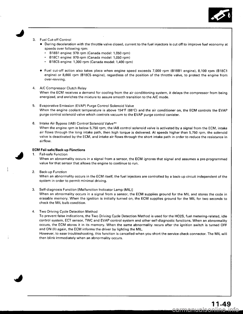
3.Fuel Cut-off Control
. Du ring dece leration with the th rottle va lve closed, cu rrent to the fuel injectors is cutoffto improvefuel economyat
speeds over following rpm:. B'1881 engine: 970 rpm {Canada model: 1.050 rpm). B18C1 engine:970 rpm {Canada model: 1.050 rpm). 818C5 engine: 1,300 rpm (Canada model: 1,400 rpm)
. Fuel cut-off action also takes place when engine speed exceeds 7,000 rpm (B'1881 engine), 8.100 rpm (818C1
engine) or 8,600 rpm (818C5 engine), regardless ol the position of the thronle valve, to protect the engine from
over-revving.
A,,/C ComDressor Clutch Relav
When the ECM receives a demand for cooling from the air conditioning system, it delays the compressor from being
energized, and enriches the mixture to assure smooth transition to the A,/C mode.
Evaporative Emission (EVAP) Purge Control Solenoid Valve
When the engine coolanl temperature is above '154'F (68'C) and the air conditioner on. the ECM controls the EVAPpurge control solenoid valve which controls vacuum to the EVAP purge control canister.
Intake Air Eypass (lAB) Control Solenoid Valve*a
When the engine rpm is below 5,750 rpm, rhe IAB control solenoid valve is activated by a signal from the ECM, intake
air flows through the long intake path, then high torque is delivered. At speeds higher than 5,750 rpm, the solenoidvalve is deactivated by the ECM, and intake air flows through the short intake path in order to reduce the resistance in
airflow.
Sell-diagnosis Function lMalfunction Indicator Lamp {MlL)lWhen an abnormality occurs in a signal from a sensor, the ECM supplies ground for the MIL and stores the code in
erasable memory. When the ignition is initially turned on, the ECM supplies ground for the N4lL tor two seconds to
check the MIL bulb condition.
Two Driving Cycle Detection Method
To prevent false indications, the Two Driving Cycle Detection Method is used for the HO2S, fuel metering-related, idle
control system, ECT sensor, TWC and EVAP control system and other self-diagnostic functions, When an abnormality
occurs, the ECM stores it in its memory. When the same abnormality recurs after the ignition switch is turned OFFand ON (ll)again, the ECM informs the driver by lighting the MlL.
However, to ease troubleshooting, this function is cancelled when you shon the service check connector. The MIL will
then blink immediately when an abnormality occurs.
4.
5.
6.
3.
4.
ECM Fail-safe/8ack.up F0nctions
1. Fail-sate Function
When an abnormality occurs in a signal from a sensor, the ECM ignores that signal and assumes a pre-programmed
value for that sensor that allows the enqine to continue to run.
2. Back-uo Function
When an abnormality occurs in the ECM itself, the fuel injectors are controlled by a back-up circuit independent of the
system in order to permit minimal driving.
11-49
Page 302 of 1680
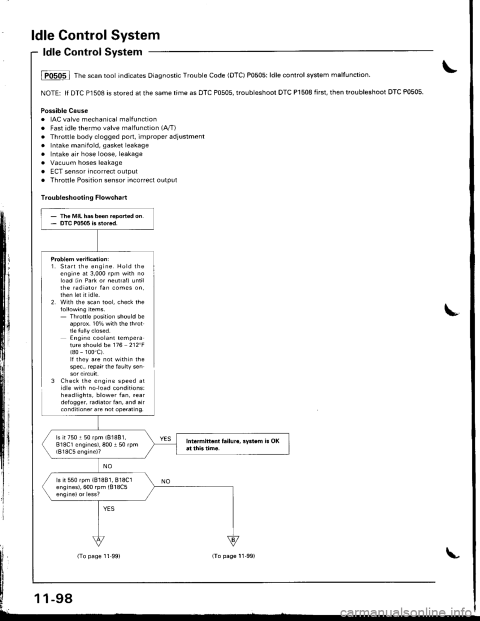
ldle Control System
ldle Control System
i P0505 | fne scan tool indicates Diagnostic Trouble Code (DTC) P0505: ldle control system malfunction,
NOTE: ll DTC Pl508 is stored at the same time as DTC P0505, troubleshoor DTC P1508 first. then troubleshoot DTC P0505.
Possible Cause
. IAC valve mechanical malfunctiorr
. Fast idle thermo valve malfunction (A"/T)
. Throttle body clogged port, improper adjustment
. Intake manifold, gasket leakage
. Intake air hose loose, leakage
a Vacuum hoses leakage
. ECT sensor incorrect output
. Throttle Position sensor incorrect output
Troubleshooting Flowchart
Problem verification:1. Start the engine. Hold theengine at 3,000 rpm wath noload 1in Park or neutral) untilthe radiator fan comes on,then let it idle.2. With the scan tool, check thefollowing items.- Throttle position should beapprox. 10% with the throttle fully closed.Engine coolant tempera-ture should be 116 212F(80 - 100'c).lf they are not within thespec., repair the faulty sensor crrcuft,3 Check the engine speed atidle with no-load conditions:headlights, blower fan, reardefogger, radiator fan, and airconditioner are not operating,
- The MIL has been reported on.- DTC P0505 is stored.
ls it 750 t 50 rpm (81881,
818C1 engines), 800 I 50 rpm(818C5 engine)?
Intermittent failur6, svstsm is OKat this tim€.
ls it 550 rpm (81881,818C1
engines), 600 rpm {818C5enginelor less?
-98
(To page 11'99)(To page 11-99)
Page 315 of 1680
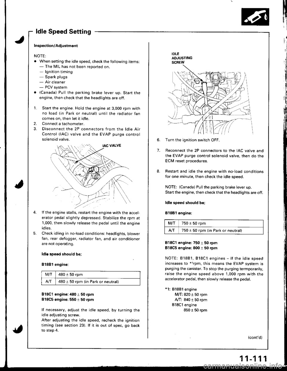
ldle Speed Setting
IDLEADJUSTINGSCREW
7.
6.Turn the ignition switch OFF.
Reconnect the 2P connectors to the IAC valve and
the EVAP purge control solenoid valve, then do the
ECM reset procedures.
Restart and idle the engine with no-load conditions
for one minute, then check the idle speed.
NOTE: (Canada) Pullthe parking brake lever up.
Start the engine, then check that the headlights are off.
ldle speed should be;
Bl88l €ngine:
Mfi750 i 50 rpm
A/T750150 rpm (in Park or neutral)
818C1 engine:750 i 50 rpm
818C5 engine: 800 i 50 rpm
NOTE: 81881, Bl8Cl engines - It the idle speed
increases to *1rpm, this means the EVAP system ispurging the canister. To stop the purging termporarily.
raise the engine speed above 1,000 rpm with the
accelerator pedal, then slowly release the pedal.
*1: 81881 engine
M/T: 820 i 50 rpm
Ay'T: 840 t 50 rpm
818Cl engine
850 I 50 rpm
(cont'd)
Inspection/Adiustmont
NOTE:
. When setting the idle speed, checkthe following items:- The MIL has not been reported on.- lgnition timing
Spark plugs- Air cleaner- PCV system
. (Canada) Pull the parking brake lever up. Start the
engine, then check that the headlights are off.
1. Start the engine. Hold the engine at 3,000 rpm with
no load (in Park or neutral) until the radiator fan
comes on, then let it idle,
Connect a tachometer.
Disconnect the 2P connectors from the ldle Air
Control (lAC) valve and the EVAP purge control
solenoid valve.
2.
5.
if the engine stalls, restan the engine with the accel
erator pedal slightly depressed. Stabilize the rpm at
1,000, then slowly release the pedal until the engine
idles.
Check idling in no-load conditions: headlights, blower
fan, rear defogger, radiator fan, and air conditioner
are not ope€tlng.
ldlo speed should be;
B188l engine:
Mlf480 :l 50 rpm
A/T480 i 50 rpm (in Park or neutral)
B18C1 engine: /t80 t 50 rpm
818C5 sngine:550 t 50 rpm
lf necessary, adjust the idle speed, by turning theidle adjusting screw.
After adjusting the idle speed, recheck the ignition
timing {see section 23). lf it is out of spec, go back
to steo 4.
Page 316 of 1680
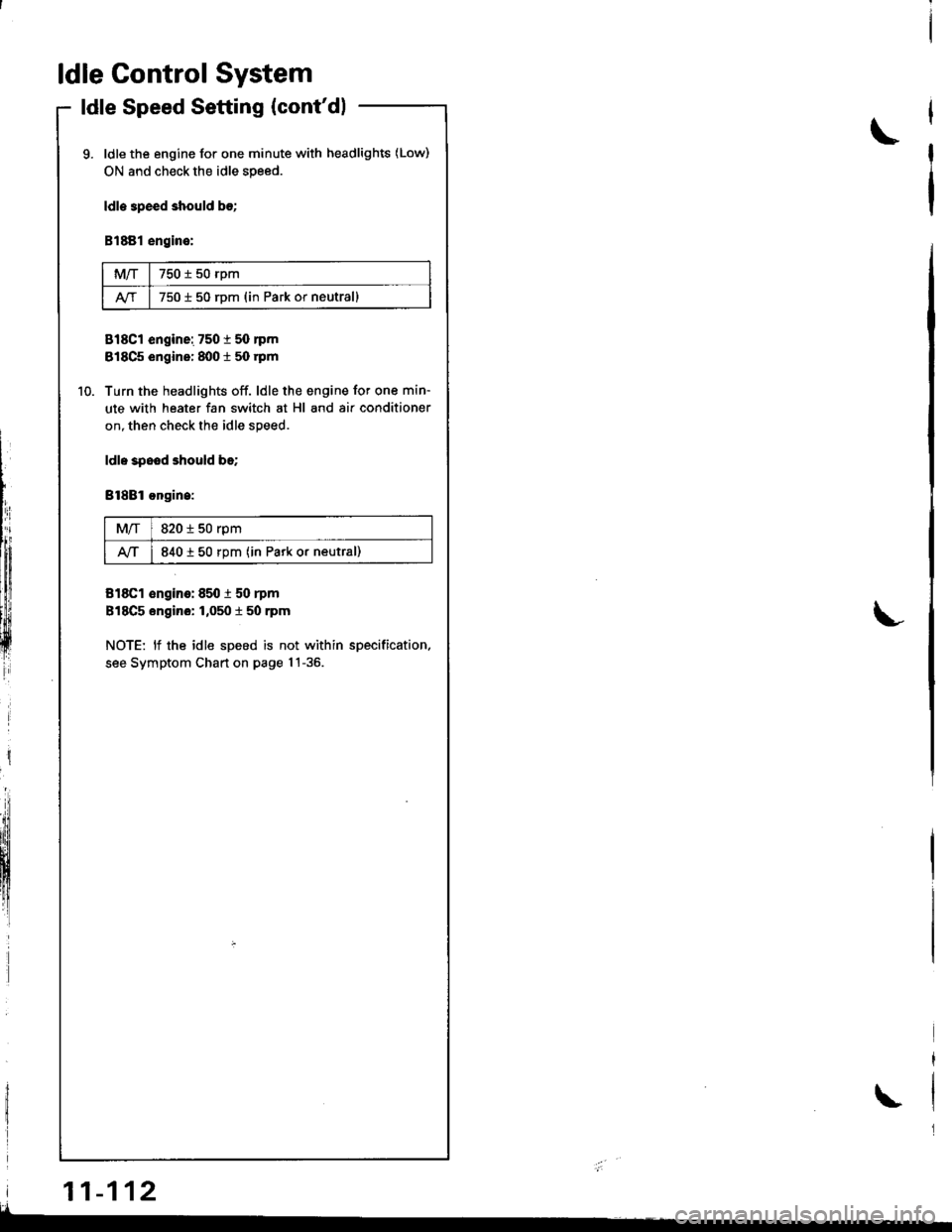
ldle Control System
ldle Speed Setting (cont'dl
ldle the engine for one minute with headlights (Low)
ON and check the idle speed.
ldle 3peed should b€;
B1881 engine:
MIT750 t 50 rpm
750 i 50 rDm (in Park or neutrall
818C1 engine: 7501 50 nm
818C5 engine: 8001 50 rpm
Turn the headlights off. ldle the engine for one min-
ute with heater fan switch at Hl and air conditioner
on, then check the idle speed.
ldl. spood should be;
Bl8Bl ongin.:
M/T820 i 50 rpm
lvT840 t 50 rpm (in Park or neutral)
818C1 €ngino: 850 i 50 rpm
818C5 engino: 1,050 t 50 rpm
NOTE: lf the idle speed is not within specification.
see Symptom Chart on page 1!-36.
\
L
i
lIh:
lffiiltfl!
ffi
| 11-112
\
I
Page 1023 of 1680
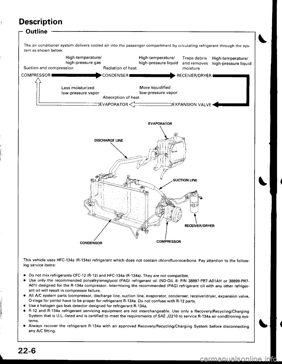
Description
Outline
The air conditioner system delivers cooled air into the passenger companment by circulating retrigerant through the sys-
tem as shown below.
High-temperature/ H ig h-tem peratu rel Traps debris High-temperature/high-pressure gas high-pressure liquid and removes high-pressure liquidSuction and compression Radiation of heat moisture
covpnEsson -tl4con oetsen -rr{ REcEIvER/DRvER
More liqu idified
low-pressure vapor
Absorption of heat
Less moisturized
low-pressure vapor
EVAPORATOR -TEXPANS|ON VALVE
EVAPORATOR
CONDENSOR
This vehicle uses HFC-134a (R-134a) refrigerant which does not contain chlorofluorocarbons. Pay attention to the follow-ing service items:
. Do not mix refrigerants CFC-12 (R-12) and HFC-134a (R-134a). They are not compatible.. Use only the recommended polyalkyleneglycol (PAG) refrigerant oil (ND-OIL 8: P/N 38897-PR7-A01AH or 38899-PR7-A01) designed for the R-134a compressor. Intermixing the recommended (PAG) refrigerant oil with any other refriger-ant oil will result in compressor failure.
. All AVC system parts (compressor, discharge line, suction line. evaporator, condenser, receiver/dryer, expansion valve.O-rings for joints) have to be proper for refrigerant R-134a. Do not confuse with R-12 parts.
. Use a halogen gas leak detector designed for refrigerant R-134a.. R-12 and R-134a refrigerant servicing equipment are not interchangeable. Use only a Recovery/Recycling/ChargingSystem that is U.L.-listed and is certified to meet the requirements of SAE J2210 to service R-134a air conditioning sys-tems.
. Always recover the refrigerant R-134a with an approved Recovery/Recycling/Charging System before disconnectingany Ay'C fitting.
22-6
Page 1038 of 1680
A/C Service Tips and Precautions
The air conditioner system uses HFC-134a (R-134a) refrigerant and polyalkyleneglycol {PAG) refrigerant oil (ND-OlL 8: P/N
38897-PR7-A01AH or 38899 - PR7 - A01), which are not compatible with CFC-12 (R-12) refrigerant and mineral oil. Do not
use R-12 refrigerant or mineral oil in this system. and do not attempt to use R-12 servicing equipment; damage to the air
conditioner system or your servicing equipment will result.
Use only service equipment that is U.L.-listed and is certified to meet the requirements of SAE J2210 to remove R-l34a
from the air conditioner system.
CAUTION: Exposure to air conditioner refrigerant and lubricant vapor ot mist can irritate eyos, nose.nd throat, Avoid
breathing th€ air conditionsr rofrigerant 8nd lubricant vapo. or mist.
lf accidental system discharge occurs, ventilate work area before resuming service.
R-134a service equipment or vehicle air conditioner systems should not be pressure tested or leak tested with comp.essed
atf,
@ some mixtures ol air and R-13i[a have been shown to be combustible at olevat6d pre3sures and cln resuh
in fire or explosion causing iniury or property damage. Nover uso compressed air to prossure te3t R-13,[8 service equip-
ment or vehicle air condition6r systems.
Additional health and safety information may be obtained from the refrigerant and lubricant manufacturers,
1. Always disconnect the negative cable from the battery whenever replacing air conditioning parts.
2. Keep moisture and dust out of the system. When disconnecting any lines. plug or cap the Jittings immediately; don't
remove the caps or plugs until just before you reconnect each line.
3. Before connecting any hose or line, apply a few drops of refrigerant oilto the O-ring,
4. When tightening or loosening a fitting, use a second wrench to support the matching fitting.
5. When recovering the system. use a R-134a refrigerant Recovery/Recycling/Charging System; don't release refrigerant
into the atmosphere.
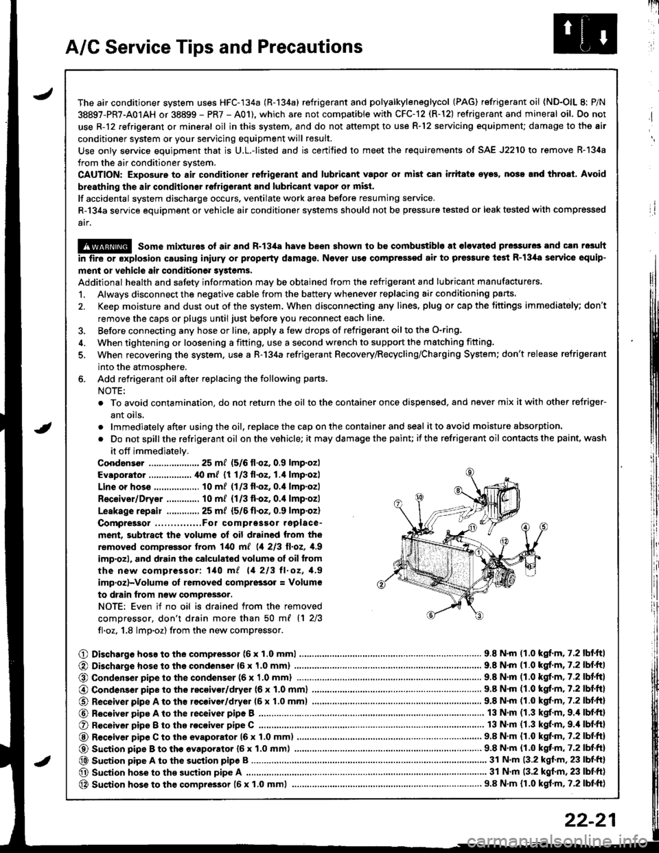
6. Add refrigerant oil after replacing the following parts.
NOTE:
. To avoid contamination, do not return the oil tothe container once dispensed, and never mix itwith other refriger-
ant oils.
.lmmediatelyafterusingtheoil,replacethecaponthecontainerandseal it to avoid moisture absorption.
. Do notspillthe refrigerant oil onthevehicle; it maydamagethe painu itthe refrigerant oil contacts the paint, wash
it off immediately.
Coodansor ..-.-.-............. 25 mt (5/6 ll.oz. 0.9 lmp.oz)
Evaporator ................. ,[0 m/ (1 1/3 fl.oz, 1.4 lmp.ozl
Line or hoss .................. 10 m? {1/3fl.oz, 0.'l lmp.ozl
Receiver/Dryer ............. 10 m/ (1/3 fl.oz, 0.4 lmp.ozl
Leskage repair .............25 m/ {5/6 fl.oZ, 0.9 lmp.oz)
Compreigor .....,......,..Fo1 comprgssor replace-
ment, subtract the volum€ of oil drained from the
removed comprassor lrom l/t{l m[ (1 213 ll.oz, 1,9
imp'ozl, and drain the calculated volume ot oil from
the new compressor: 140 m/ 11 213 ll.oz, 1.9
imp.oz)-Volum€ oI removed comprsssor = Volum€
to drain trom n€w compressor.
NOTE: Even if no oil is drained from the removed
comDressor, don't drain more than 50 m{ {1 2/3
fl.oz. 1.8 lmp.oz) from the new compressor.
O Dischargo hoso to the compressol (6 x 1.0 mml............................... 9.8 N'm (1.0 kgf.m, 7.2 lbf'ftl
@ Di3charge hose to the condenser {6 x 1,0 mm)
@ Condonser pipe to the condenser (6 x '1.0 mml
9.8 N'm (1.0 kgl.m, 7.2 lbf.ftl
.. 9.8 N.m (1.0 kgf.m,7.2lbl.ltl
@ Condenser pipe to the rec€ivor/dryer (6 x 1.0 mml
O Receiver pipe A to th8 recoiver/dryer (6 x 1.0 mml
@ Receiyar pipe A to lhe receiver pipe B ,...........
O Receiver pipe B to th8 .ocoiver pipe C ............
@ R€ceiver pipe C to the evaporator 16 x 1.0 mm)
@ Suction pipe B to th€ evaporator {6 x 1.0 mm) .......,.
@ Suqtion pipe A to the suction pipe B
O Suction hose to the suction pipe A ...........,.
@ Suction hose to the compressor 16 x 1.0 mml
9.8 N.m (1.0 kgf.m, 7.2 lbf.ftl
9.8 N'm (1.0 kgf.m, 7.2 lbf.fr)
13 N.m (1.3 kgf.m. 9.4 lbf.ft)
13 N.m (1.3 kgf.m,9.'l lbf.ftl
9.8 N.m (1.0 kgt m. 7.2 lbf.ftl
...... 9.8 N.m {1.0 kqf'm, 7.2 lbf.ft)
........ 31 N'm (3.2 kgf.m, 23 lbf.ft)
............ 31 N.m (3.2 kgf.m,23 lbtft)
..................... 9.8 N.m {r.0 kgf.m, 7.2 lbtft)
22-21
Page 1039 of 1680
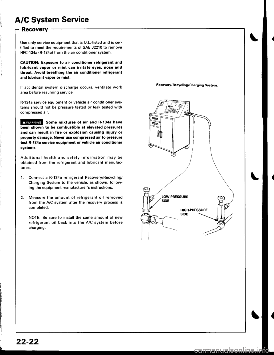
A/C System Service
Recovery
Use only service equipment that is U.L.-listed and is cer-
tified to meet the requirements of SAE J2210 to remove
HFC-134a (R-134a) from the air conditioner system.
CAUTION: Exposure to air conditioner refrigerant and
lubricant vapor or mist can irritale eyes. nose and
throat. Avoid breathing the air conditioner rclrigerant
and lubricant vapor o. mist.
lf accidental system discharge occurs, ventilate work
area before resuming service.
R-134a service equipment or vehicle air conditioner sys-
tems should not be Dressure tested or leak tested with
compressed air.
@ some mixtures of air and R-134a have
been shown to be combustible at €levated pros3ures
and can result in lire or explosion causing iniury or
plop€rty damage. Never use comprossgd air to pressure
iest R-134a service equipment or vehicle air conditioner
sYstsms.
Additional health and safety information may be
obtained from the refrigerant and lubricant manufac-
tures,
Connect a R-134a refrigerant Recovery/Recycling/
Charging System to the vehicle. as shown, follow-
ing the equipment manufacturer's instructions.
Measure the amount of refrigerant oil removed
from the IVC system after the recovery process is
completed.
NOTE: Be sure to install the same amount of new
refrigerant oil back into the A/C system before
charging.
Recov€ry/Recycling/Cha.ging Systom.
HIGH.PRESSURESIDE
't.
22-22
Page 1041 of 1680
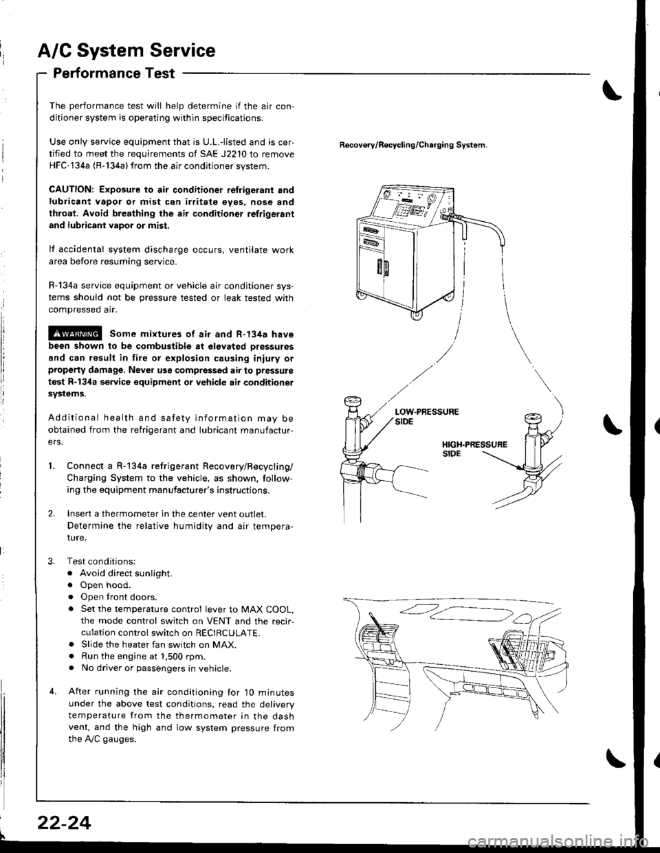
A/C System Service
Performance Test
The performance test will help determine if the air con,
ditioner system is operating within specifications.
Use only service equipment that is U.L.-listed and is cer,
tified to meet the requirements of SAE J2210 to remove
HFC-134a (R-134a) from the air conditioner svstem.
CAUTION: Exposure to air conditioner retrigerant and
lubricant vapor or mist can irritate eyes, nose and
throat. Avoid breathing the air conditioner refrigerant
and lubricant vapor or mist.
lf accidental system discharge occurs, ventilate work
area before resuming service.
R-134a service equipment or vehicle air conditioner sys-
tems should not be pressure tested or leak tested with
compressed arr.
@ some mixtures of air and R-134a have
been shown to be combustible at elevated Dressures
and can result in fire or explosion causing iniury orproperty damage. Never use compressed air to pressure
test R-134a service equipment or vehicle air conditioner
systems.
Additional health and safety information may be
obtained from the refrigerant and lubricant manufactur-
ers.
Connect a R-134a refrigerant Recovery/Recycling/
Charging System to the vehicle, as shown, follow-
ing the equipment manufacturer's instructions.
Insen a thermometer in the center vent outlet.
Determine the relative humidity and air tempera-
IUre.
Test conditions:
. Avoid direct sunlight.
. Open hood.
. Open lront doors.
. Set the temperature control lever to MAX COOL,
the mode control switch on VENT and the recir-
culation control switch on RECIRCULATE.. Slide the heater fan switch on MAX.. Run the engine at 1.500 rpm.. No driver or passengers in vehicle.
After running the air conditioning for'10 minutes
under the above test conditions, read the delivery
temperature from the thermometer in the dashvent, and the high and low system pressure from
the A,/C gauges.
Recovo.v/Recycling/Charging System.
LOW.PRESSURE
l
22-24
Page 1047 of 1680
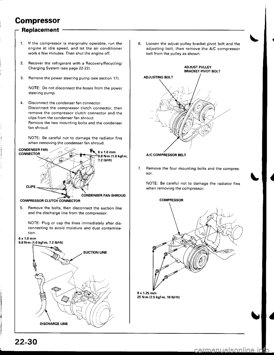
Compressor
Replacement
lf the compressor is marginally operable, run the
engine at idle speed, and let the air conditioner
work a few minutes. Then shut the engine off.
Recover the refrigerant with a Recovery/Recycling/
Charging System \see page 22-22).
Remove the power steering pump (see section 17).
NOTE: Do not disconnect the hoses from the power
steering pump.
Disconnect the condenser fan connector.
Disconnect the compressor clutch connector, then
remove the compressor clutch connector and the
clips from the condenser fan shroud
Remove the two mounting bolts and the condenser
fan shroud.
NOTE: Be careful not to damage the radiator fins
when removing the condenser fan shroud.
1.0 mmN.m (1.0 kgt.m,rbf.ftt
CONDENSER FAN SHROUD
COMPRESSOR CLUTCH CONNECTOR
5. Remove the bolts, then disconnect the suction line
and the discharge line from the compressor.
NOTE: Plug or cap the lines immediately aiter dis-
connecting to avoid moisture and dust contamina-
tio n.
6x1.0mm9.8 N.m (1.0 kgf.m, 7.2 lbf.ft)
22-30
6. Loosen the adjusl pulley bracket pivot bolt and the
adjusting bolt, then remove the A/C compressor
belt from the Dullev as shown.
ADJUSTING BOLT
A/C COMPRESSOR BELT
Remove the four mounting bolts and the compres-
sor.
NOTE: Be careful not to damage the radiator fins
when removing the compressor.
7.
./.,
COMPRESSOR
Page 1055 of 1680
A/C System Service
Evacuation
Use only service equipment that is U.L.-listed and is cer-
tified to meet the requirements of SAE J2210 to remove
HFC-134a (R-134a) from the air conditioner svstem.
CAUTION: Exposure to air conditioner refrigerant and
lubricant vapor or mist can irtitate eyes, nose and
throat. Avoid breathing the air conditioner refrigerant
and lubricant vapor or mist.
lf accidental system discharge occurs, ventilate work
area before resuming service.
R-134a service equipment or vehicle air conditioner sys-
tems should not be pressure tested or leak tested with
compressed air.
!@@l some mixtures ot air and R-t3ita have
been shown to be combustible at elevated pressures
and can result in fire of explosion causing injury orproperty damage. Never use compressed air to pressure
test R-134a service equipment or vehicle air conditionet
svstems.
Additional health and safety information may be obtained
from the refrigerant and lubricant manufacturers.
When an A"/C Svstem has been ooened to the atmo-
sphere, such as during installation or repair, it must
be evacuated using a R-134a refrigerant Recovery/
Recycling/Charging System. (lf the system has been
open for several days, the receiver/dryer should bereplaced, and the system should be evacuated for
several hours.)
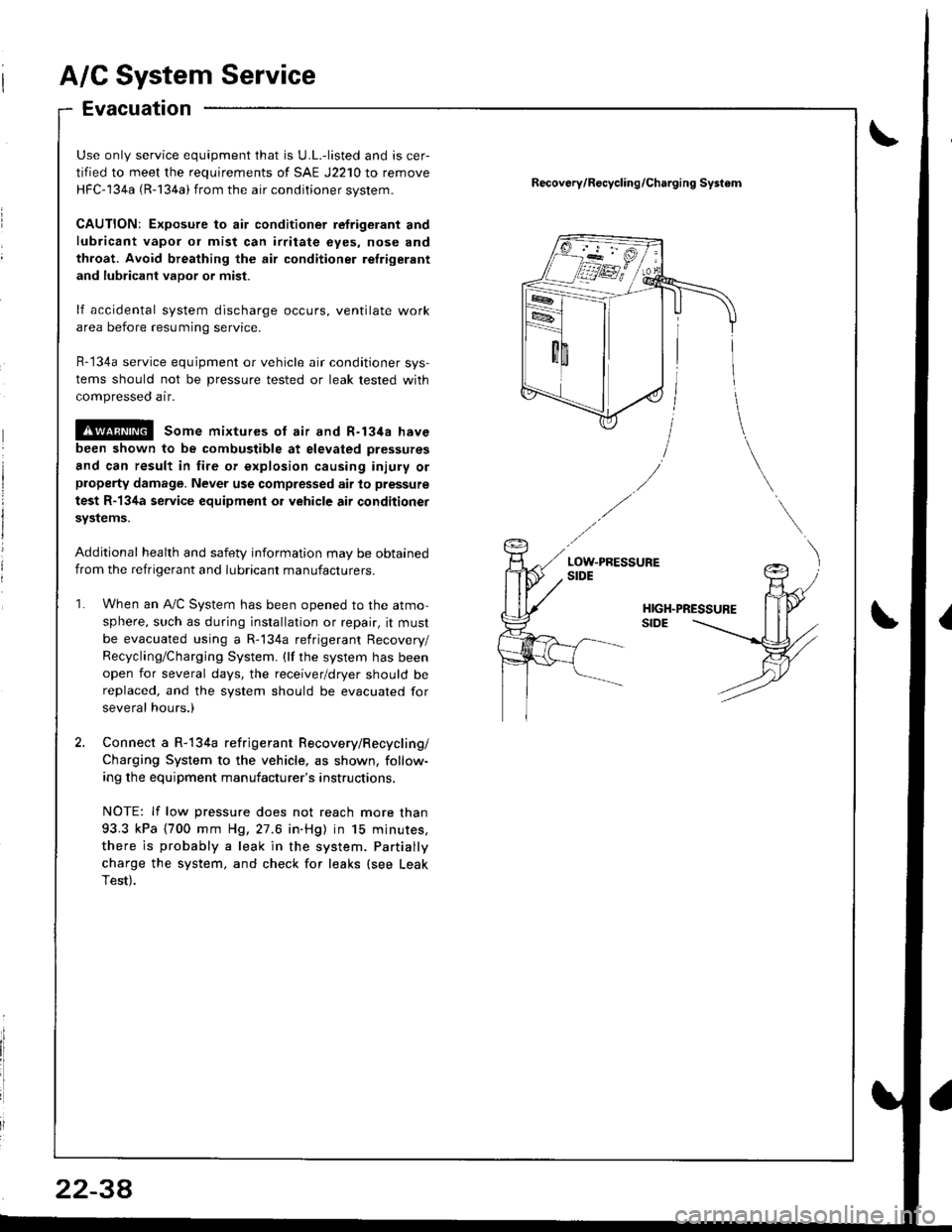
Connect a R-134a refrigerant Recovery/Recycling/
Charging System to the vehicle, as shown, follow-
ing the equipment manufacturer's instructions.
NOTE: lf low pressure does not reach more than
93.3 kPa (700 mm H9,27.6 in.Hg) in 15 minures,
there is probably a leak in the system. Partially
charge the system, and check for leaks (see Leak
Test).
Recov6ry/R€cycling/Charging Systom
2234